SetonixSynth Laka Manual

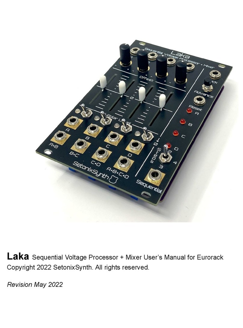
Laka Sequential Voltage Processor + Mixer Build Manual - Eurorack
Copyright 2022 SetonixSynth. All rights reserved.

Hello and thank you for building the Laka Sequential Voltage Processor + Mixer. We hope you will find its
processing power most pleasing!
Assembly Instructions:
1. Install surface mount components on the rear of the PCB. We recommend using No-Clean liquid flux
on the board before applying quality solder paste such as Chip-Quik SMD291SNL, tweezing components
onto the board, and reflowing with a hot air station or oven.
-Take special care when placing and soldering IC’s U1-U9; the fine pitch of the legs on these
parts makes it likely that solder bridging will occur. In order to ensure there is no bridging, use
copper braid to “wick away” excess solder on the pins of these IC’s after initially flowing the
board. Using a multimeter to test for continuity after solder touch-up is also a good idea. (If
strange behavior occurs upon power-up, it is very likely that a solder bridge on a TSSOP package
is the culprit.)
2. Solder rear through-hole parts: 10-pin Eurorack power header, 2x 6-pin “expander” headers, ten
Multiturn trimmers, and 2 TO-92 TL431 regulators (U10 and U11) if, and only if, you did not use
SOT-23-3 TL431 regulators in footprints U10B and U11B.

3. Once all rear through-hole parts have been soldered, place one of the B100k faders in a footprint on
the Panel side of the board and use a couple fingers to hold it snug against the PCB so that all pins sit as
evenly as possible in their respective through-holes. This should ensure that it is relatively straight in
relation to the panel. While holding the fader in place, flip the PCB over and use your iron to solder one
and only one leg of the fader so that it is held stationary. Leave the other pins of the fader you just
soldered for later. Repeat this process for the other three faders, making sure that you only solder one leg
on each fader, and hold it firmly in place until the solder has set.
4. Inspect the four fader potentiometers thoroughly to make sure they are all sitting flat against the PCB
and that the faders are all at nice 90-degree angles to the PCB and not crooked. If any of the fader pots
are crooked or misaligned, use a finger to gently press it into place while using your soldering iron to
reflow the one solder joint so that the fader can slot into place.
5. Once you are visually satisfied with the position of all four fader potentiometers, insert all the other
frontal hardware and the LED into the other side of the PCB, but do not solder any of these parts yet. I
find it easiest to insert them in this order: plastic-shaft potentiometers (these should snap into place), then
Thonkiconn jacks, then Switches, and finally the 8 LED’s.
-Double check all the little details: bi-color LEDs should be used in all positions marked
“BI-COLOR,” single-color LEDs should be used in all positions marked “SINGLE COLOR,” and
the flat end of all LEDs should correspond to the square pad, marked “k” for the single colors. The
four SPDT ON-ON switches should be in the positions marked “ON-ON”, while the one SPDT
ON-OFF-ON switch goes in the position marked “ON-OFF-ON.” The polarity of the switches
doesn’t matter but I like to put the “notch” side of each toggle facing downward for appearance’s
sake.
6. Place the panel over the hardware and hand-tighten the appropriate nuts over the switches and
Thonkiconn jacks so that a nice “sandwich” is formed. Be sure to hold the PCB in place with some fingers
while doing this, as the PCB can fall out and then you have to repeat step 3!
It may also be helpful to use a table vise if you have one to hold the PCB in place while soldering.
7. With the PCB facing up and panel facing down, double check that all hardware is properly seated in the
appropriate PCB holes. If it is, position each front LED so it sits as far forward as possible in the front
panel hole and solder one leg. Do this with all 8 LED’s, then flip the module over to make sure all 8 LEDs
are relatively even peeking through the panel. If they are not, reflow the one leg of the offending LED and
move it so that all LEDs sit evenly. Once you are satisfied, solder the other leg of each LED and clip off
the protruding legs.
8. Solder the rest of the frontal hardware into place except the four B10k center detent plastic
potentiometers (RV2, RV4, RV6, and RV8). Be careful to mind the tip of your soldering iron so that it does
not melt any of the through-hole trimmers or cause any shorts on the circuit board.
9. Once all other hardware is secured, solder the four plastic potentiometers using the following method:
-Solder one leg of one pot
-Check to see if the pot is mounted in such a way that it does not touch the panel when turned
-If it isn’t, use a finger to adjust the pot’s position while heating the one soldered pad
-Once the pot is not touching the panel, solder the second leg, double check and solder the pins
-Repeat for other potentiometers

10. Laka is a dense PCB with lots of hardware, and it’s very easy to miss a solder joint in the excitement
to finish the module. Do yourself a favor and double- or even triple-check to make sure every single piece
of hardware and all LEDs are soldered to each pad provided with an ample amount of solder, including
the mechanical pads. This step will make it much more likely your module works first time!
11. If you are confident everything has been soldered in place, we highly recommend performing the
following test before powering on the module for the first time:
a. Set your Multimeter to the Resistance measurement setting (20kΩ if you have to specify range)
b. Place the red (positive) probe on one of the two +12V Input pins at the top of Laka’s 10-pin power
header on the back of the module, and the black (negative) probe on one of the power header’s
six central Ground pins. Observe the resistance on your Multimeter: it should read as a value
above 10kΩ, usually around 14 or 15kΩ.
c. Now, place the red (positive) probe of your Multimeter on one of the six central Ground pins and
place the black (negative) probe on one of the two -12V Input pins at the bottom of the power
header. Observe the resistance reading: it should be similar to the first value (above 10kΩ and
more likely about 14 or 15kΩ).
d. If both values are in the ballpark, this part is over and you can proceed to regular testing and
calibration.
e. If either value reads much lower than 10kΩ, there is most likely a short or at least some stray
capacitance between one of the power rails and ground, which will cause the module to not work
properly and could possibly damage the Schottky power diodes if powered on, as excessive
current will flow across the diode.
f. Inspect the board for visible shorts, particularly around the 9 TSSOP (fine pitch) IC’s. If any of the
chips even seem to have a little too much solder on the legs (or if you see a short), use copper
braid and your soldering iron to wick as much excess solder as you can from any area that looks
potentially shorted.
g. As you wick away problematic areas, continue measuring the resistance between power pins as
described above until the resistance values are correct.
11. Now it’s time to test your Laka. Plug it in, making sure your power cable’s -12V connection, usually
indicated by the red stripe, is oriented downwards corresponding with the silkscreen. Laka is reverse
diode protected, but we still do not recommend plugging it in backwards for any reason. Then, turn on
case power and observe the behavior of Laka’s LEDs.
With nothing patched to any input, the Offset knobs should influence the behavior of the Channel LEDs,
as should the Bi-Polar Level Faders if the “Zero” switches are in an upward position. Likewise, pressing
the “Advance” button should allow you to manually cycle through the four channels as indicated via the
four single-color LEDs. It’s also worth spending some time patching various signals to the four Channel
inputs and observing the behavior of all 9 Outputs on an oscilloscope, or in a pinch just another module
with LED indication that will respond to CV. Don’t forget to test the Clock and Reset inputs with some 5V
triggers or gates as well in order to confirm that the Sequencer is functional.

12. Calibrate your Laka.
(You will need a multimeter and 1V/Oct voltage source)
1. Power on Laka and allow it to warm up for a few minutes.
2. Use a multimeter on the DC Voltage setting to adjust +VREF and -VREF. Connect the black probe to
one of the terminals marked “-Gnd-” on the Exp1 header or some other circuit ground such as the sleeve
of a Thonkiconn jack, and monitor the voltages present at the test points marked “+Vref” and “-Vref”.
Adjust the corresponding trimmers marked “+Vref Adj” and “-Vref Adj” so that they are as close as
possible to 5.0V and -5.0V respectively. These can be adjusted for other values but we highly
recommend the “stock” setting of +/-5V, both for the safety of other modules and playability of
Laka.
3. Put all four “Zero” switches in the downward (Zero) position and set all four “Offset” knobs to the Center
Detent position. Use your multimeter to monitor the output of Channel A while adjusting the rear trimmer
labeled “1” so that the output of the channel is as close to 0V as possible.
--The center detent of each pot will have a “range” of approximately 100-150mV which will
inevitably cause the output to change slightly based on various factors such as which direction it
is being rotated, so just do your best to center this “range” around 0V.
Repeat this step for the other Offsets. The rear trimmer labeled “2” corresponds to Channel B output, “3”
to C, and “4” to D.
4. Calibrate the channel Inputs. This can be done a few ways, depending on tools available:
-Set all Offsets to the center (null) position. Zero the channels which are not being tested by
turning the Zero switches to the down position. Patch a decently precise voltage output such as
the 1V/Oct output from a well-calibrated sequencer or precision voltage source into the Channel
A input and position the Channel A fader at full amplitude (all the way up). Patch Output A into the
1V/Oct input of the best-tracking VCO in your rack and use a frequency counter (such as the Hz
mode on your multimeter if it has one) to monitor the VCO’s frequency. Adjust trimmer “A” so that
an increase of 1V from your voltage source corresponds as closely as possible to an increase of
1 Octave (precisely double the frequency) as indicated by the frequency counter. This might
involve going through the octaves a few times to ensure tracking is good over at least 3-4
octaves. Repeat for the other three channels, with the trimmers labeled “B,” “C,” and “D”
corresponding to the appropriate Channel inputs.
The normalization from one channel to the next means that the signal patched to Input A does not
have to be repatched to test a different Channel, although due to the cumulative impedance of
each channel input, each channel should be switched to “Zero” when not in use to avoid
cumulative loading of the source signal, which may cause the input voltage to droop slightly and
throw off the calibration.
-Quick calibration: Patch your sequencer into the Channel A input and patch Channel A output to
the 1V/Oct input of your favorite oscillator and tune by ear. Repeat for the other three channels
until you are happy with the tuning.
5. All done! Enjoy your new Sequential Voltage Processor!
Thank you for building the Laka!
Table of contents
Other SetonixSynth Signal Processor manuals
Popular Signal Processor manuals by other brands

PCB Piezotronics
PCB Piezotronics 483C15 Installation and operating manual

BSS Audio
BSS Audio BLU-50 installation guide

FeelTech
FeelTech SGP10 S Series user manual
Radial Engineering
Radial Engineering REAMP JCR STUDIO REAMPER user guide
IRIS
IRIS P522 Applications manual
Freescale Semiconductor
Freescale Semiconductor DSP56002 user manual
