SetonixSynth Laka User manual

Laka Sequential Voltage Processor + Mixer User’s Manual for Eurorack
Copyright 2022 SetonixSynth. All rights reserved.
Revision May 2022

Hello and thank you for using the Laka Sequential Voltage Processor + Mixer for Eurorack modular. We
hope you will find it to be useful and fun!
Technical Specifications (Eurorack standard)
Width: 16hp
Depth: 28mm
Peak Current Draw: 65mA @ +12V, 65mA @ -12V
Input Impedance (Channels A-D, Calibrated): 97k approx. per input
Input Impedance (Clock): 100kΩ
Input Impedance (Reset): 47kΩ
Output Impedance (All Outputs): 1kΩ
Output voltage range (All Outputs): +/-11.5V (23Vp-p) approx.
Clock Threshold: ↑ +5V (Advances on rising edge)
Reset Logic Threshold: +5V
1. Connecting your Laka
Connect a power cable to the pin header at the top of the Laka pcb. The -12V side of the connector
should be facing downwards, and must be aligned with the silkscreen stripe indicator for proper use. This
module is reverse diode protected, but we do not recommend that you plug it in backwards to see what
happens.
CAUTION: Laka uses so-called “rail-to-rail” op-amps to process and mix signals. This means that it is
capable of handling voltage inputs equal to the swing of its power rails and outputting voltages at a
potential amplitude of approximately +/-11.5V peak to peak on a typical Eurorack power supply. This is a
very wide range! Signals of this amplitude will not damage Laka, but they may cause overdriving, strange
behavior, or damage in other circuits not designed to handle such a wide voltage swing, particularly
synths or devices powered by lower voltages. When in doubt, the amplitude of any Channel may easily be
reduced by moving the corresponding fader closer to the middle position and removing the voltage offset.
2. Theory of Operation
Laka is designed to be a powerful multi-functional hub for routing voltages within a modular system of any
size. It uses precision resistors, modern low-noise/rail-to-rail op-amps and switch IC, and audio-grade
hardware to function as a true voltage “Swiss Army knife,” equally at home routing audio or control
signals.
We drew inspiration for Laka’s design from the classic console audio mixer, which has been used
extensively by thousands of illustrious musicians and producers and accepted as an instrument in itself
for decades. The Eurorack modular format has incorporated this as well, with many users benefiting from
a powerful in-rack audio mixer with faders, mutes, aux sends, sub-mixes etc.
We felt that Control Voltage could benefit from the same treatment, and thus Laka was born. The large
attenuverting faders make it easy to dial in precise voltage amounts, and then, crucially, add or subtract
offset voltage if desired to bring each output within the desired window for use. This has been a classic
synthesizer function for decades, but Laka offers several improvements: high headroom, low noise,
modern low-noise/low-offset op-amps, and most importantly: simultaneous access to all its features at
once. No Easter eggs, no hidden modes: Laka’s power comes from its incredible potential for combining,

feedback-ing, processing, and re-processing, underpinned by immediate and inspiring tactile and visual
feedback. This is a processor built to match and complement the many amazing voltage sources of
modern Eurorack modular, with a generous helping of fun and style!
3. Summary of Functions
Laka signal flow diagram.
Voltage Processor section:
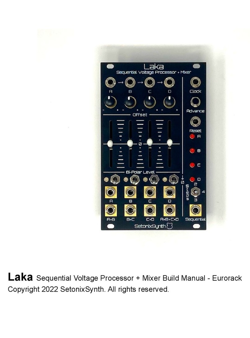
A, B, C, D (Upper): DC Coupled voltage inputs. Accepts input signals of up to approx. +/-11.5V and
routes them to the four Voltage Processor channels.
-Normalization of inputs: The four inputs are normalized from left to right in the manner indicated
by the front panel arrows, so that with nothing plugged into Jack D it will engage with the voltage
input present at Jack C, which will engage with Jack B when unplugged, which will in turn engage
with Jack A. As such, for example, a signal patched to Jack A will be routed to Inputs B, C, and D
if nothing is inserted into any other Input.
-With nothing patched to Jack A, its input is normalized to +5V via a protective 1kΩseries
resistor, so the faders of unpatched/unused channels following the normalization scheme may be
used to manipulate a voltage offset. Note that every channel with the fader engaged for use as a
voltage offset will load our “virtual” +5V reference and cause a slight drop in the faders’ actual

voltage range. Analog, baby! To create the most stable “stepped” voltage possible if required,
engage the “Zero” switch on the channel to disable the fader and use the channel Offset knob to
dial in a voltage output from +5V to -5V.
OFFSET: Adds an adjustable voltage offset of +/-5V to the Channel and Mix/Submix output directly below
it. For example, the Offset knob below Input A will affect both Output A and Output A+B, the Offset knob
below INPUT A will affect both Output B and Output B+C, and so forth. In the center position, an Offset is
effectively nullified and has minimal influence over the final voltage output of corresponding channels. The
behavior of the Offset knobs is also subject to the following:
-Phase cancellation prevents each Offset knob from adding or subtracting an Offset voltage from
Mix outputs apart from those directly underneath them, even if they nominally control the Offset
for that Channel. For example, the B Offset will not influence the final voltage of Output A+B, C
Offset will not influence the final voltage of Output B+C, and so forth (except in cases of clipping;
see the next bullet point). This prevents Offsets from canceling each other out or combining to
shift the Mix outputs outside of a useful voltage range.
-If a Channel output is being saturated (limited to the supply rail) due to the application of Offset,
this “clipping” will still translate to all Mix outputs utilizing this Channel as well. For example, if
Output B becomes saturated due to its Offset knob pushing it to the power rail, it will appear as a
similarly clipped waveform at outputs A+B and A+B+C+D as well, despite Offset B still being
nullified in its routing to these Mix outputs.
BI-POLAR LEVEL: Each fader controls the output level of the voltage present at the Voltage Input
directly above it, which is then added to, or subtracted from, the setting of the corresponding Offset knob
and routed to the Channel outputs. Gain for each channel varies from x1.0 of the input with the fader fully
up, to approximately zero when positioned at the “0” line, to x(-1.0), or full phase inversion, with the fader
fully down. Each fader has a linear response in both directions.
BI-COLOR LEDS: Indicate the voltage present at the Channel output directly below it, including Offset
voltage added or subtracted. Green light output corresponds to increasing positive voltage and Red light
output corresponds to increasing negative voltage, while audio-rate signals around 0V will produce a nice
yellow-orange color.
↓0: Zeroing switches. When in the Down position, each Switch will fully “mute” the corresponding channel,
as if the fader were positioned perfectly at 50%, and will not pass any input signal to the output, though
the Offset knobs can still be used to add or subtract voltage from the final output.
A, B, C, D (Lower): Channel outputs. Each jack outputs a bi-polar processed version of the
corresponding voltage input with Offset added or subtracted, with a total output limited to the supply rail
range of approx. +/-11.5V.
A+B, B+C, C+D, A+B+C+D: Mix outputs. Each of these produces a signal which is a sum of the
corresponding faders (for example, bi-polar processors A and B for Mix Output A+B) plus the Offset knob
directly above the output (for example, Offset C is added to Output C+D).

Sequencer Section:
CLOCK: Advances the channel being routed to the Sequential output. This input expects a sharp rising
edge of at least 5V from Peak to Trough in order to advance the step. This input can be used with bipolar
low- or audio-frequency Square or Pulse wave signals from a VCO or similar as well as traditional Gate or
Trigger signals.
ADVANCE: Advances the channel being routed to the Sequential output on its initial rising edge and
prevents the sequencer from advancing due to a Clock input as long as it is held down. This function will
be overridden by a Logic High voltage fed to the Reset input, which will cause the Sequencer to reset to
Channel A.
RESET: Resets the sequencer to Channel A and holds it there as long as it is receiving a Logic High of
approximately 5V or greater. This input will override the functionality of the Clock input and Advance
button and hold the Sequential output at Step A as long as it is receiving a logic HIGH.
LEDs A, B, C, D: Indicate which Channel output voltage is currently present at the Sequential output.
STEPS: Controls the number of channels the sequencer will step through before resetting to Channel A.
2 Steps will encompass Channels A and B, 3 Steps Channels A, B, and C, and 4 Steps will step through
all four channels.
SEQUENTIAL: Outputs the signal present at the Channel output which corresponds to the step indicated
by LEDs A, B, C, and D.
-Note that this jack cannot and should not be used as an Input in the same way as the Common
jack on traditional Bi-Directional/Sequential Switches.
4. Patch Ideas
"Voltage Fader Bank"
The most simple thing Laka can be used for. Good for testing that Laka is working. With nothing patched
to any input and the “Zero” faders switched to the upwards/on position, +5V is normalized to Input A via a
series resistor and thus each fader may be used to provide a variable voltage offset, with the “window” of
each fader adjustable via the corresponding Offset knob. (In this mode, the reference is subject to some
loading with multiple channels engaged due to a protective feature; see “Summary of Functions” for more
info.) For instance, with the Offset knob fully clockwise the Fader can be used to output a voltage from
approximately -5V to +5V, while centering the Offset knob changes the range from about 0V-10V. The Mix
outputs will simultaneously output various combinations of the offset voltages, and the Sequential output
will output the DC voltage indicated by the Sequencer LEDs.
“Function Sequencer”
Patch the output of a Trigger- or Gate-controlled Envelope or Function generator to Laka’s Channel A
input, and patch the Gate or Trigger controlling the Envelope to Laka’s Clock input. Patch the Sequential
output to anything that responds well to an envelope, such as a filter’s cutoff or a VCA’s amplitude. Use
the four Channel Faders and Offsets to create a complex, bi-polar “sequenced” version of the function
input.
“Harmonic Oscillator”

Patch the Square or Pulse Wave output of the SetonixSynth Rottnest (or your favorite VCO) to Laka’s
Clock input and monitor the Sequential output for audio. With nothing patched to the Channel inputs, Laka
will step through the voltage offsets created by each fader well into Audio rates, while patching a
waveform (non-Square/Pulse waves will produce the most interesting sound) from the VCO to Channel A
will allow the user to create a complex waveform that flips through versions of the input. Various
waveforms from the VCO or even other signals such as noise, granular audio, or LFOs may be fed to the
channel inputs and the Sequential output will happily flip through them at the frequency of the controlling
VCO.
“Sequence Selector”
Patch multiple sequences into the Channel inputs and use the Advance button or Clock input to cycle
through them via the Sequential output, with a gain very close to exactly x1 with the fader up or exactly
x-1 with the fader fully down allowing for “inverse” sequences. This is mostly effective for controlling
non-pitch parameters, but with a little tweaking of the Offset knobs this technique may be used
reasonably well with melodic sequences as well.
“Command Center”
Patch four important audio or CV sources into the four Channel outputs of Laka. Patch the single Channel
outputs to their typical destinations, then patch the Submix and Mix outputs to some of those secondary
parameters on that new module you’ve been meaning to explore. Freak out!
5. FAQs / Questions We Presume Will Be Asked Frequently
Q: Why do I sometimes hear a click when I cycle through audio sources using the SEQUENTIAL output?
A: The click you are hearing is the difference in OFFSET from one channel to the next, which is causing
an audible jump in voltage as the channel routed to the SEQUENTIAL output changes. Simply center the
OFFSET knob to use the corresponding channel with a bipolar audio input, or use the OFFSET knobs to
“center” audio-rate input voltages from different sources (e.g. turn the OFFSET to -5V to make a 0-10V
input signal bipolar) so that they sit in approximately the same voltage range, which will minimize the
voltage “jump” between steps.
Q: Why doesn’t Laka have CV control over amplitude?
A: This would have complicated the design, made Laka more confusing to use and compromised its core
functions. Instead, we recommend experimenting with VCAs in Laka’s signal path, particularly before the
inputs. With a little creativity, Laka can be used with a VCA to create a Four-Quadrant Multiplier, highly
controllable Ducking, and more. Meanwhile, the Sequential section’s power is in its simplicity, providing a
straightforward but highly functional and adaptable way to scan through the channels in a way that works
with the left-to-right flow of the module. A fully fleshed-out, CV controllable selection module that can be
used with Laka is planned for the future.
Q: Who/what inspired this module?
A: We had a bunch of faders from a previously abandoned project sitting in their packing material and not
going to good use, and reckoned they would be perfect for a feature-packed Voltage Processor module.
We sat down and thought about the fun, practical and powerful Voltage Processor we would like to use,
and a striking concept was to give the bi-polar processor the same treatment as a typical console mixer

(including an “audition” function, here presented as the Sequential section), with the wide range of control
and flexibility that comes with a good console.
Laka in its final form would not have been possible without circuits and ideas pioneered and/or generously
shared in various forms by Serge Tcherepnin, Ken Stone/CGS, and Fonitronik, plus countless others.
Appendix: How to Calibrate Laka
This section explains how to calibrate the Voltage References, Offset pots, and Channel Input levels for
Laka.
Please note that factory units come pre-calibrated and you should not mess with the rear trimmers unless
you have some experience testing and calibrating modules. For queries about this module, technical or
otherwise, please feel free to email [email protected].
1. Power on your Laka module and allow it to warm up for a few minutes.
2. Use a multimeter on the DC Voltage setting to calibrate +VREF and -VREF. Connect the black/negative
probe to one of the terminals marked “-Gnd-” on the Exp1 header or some other circuit ground such as
the sleeve of a Thonkiconn jack, and monitor the voltages present at the test points marked “+Vref” and
“-Vref”. Adjust the corresponding trimmers marked “+Vref Adj” and “-Vref Adj” so that they are as close as
possible to 5.00V and -5.00V respectively.
3. Put all four “Zero” switches in the downward (Zero) position and set all four “Offset” knobs to the Center
Detent position. Use your multimeter to monitor the output of Channel A while adjusting the rear trimmer
labeled “1” so that the output of the channel is as close to 0.0V as possible.
-The center detent of each pot will have a “range” of approximately 100-150mV which will
inevitably cause the output to change slightly based on various factors such as which direction it
is being rotated, so just do your best to center this “range” around 0V.
Repeat this step for the other Offsets. The rear trimmer labeled “2” corresponds to Channel B output, “3”
to C, and “4” to D.
4. Calibrate the channel Inputs. This can be done a few ways, depending on tools available:
-Set all Offsets to the center (null) position. Zero the channels which are not being tested by
turning the Zero switches to the down position. Patch a decently precise voltage output such as
the 1V/Oct output from a well-calibrated sequencer or precision voltage source into the Channel
A input and position the Channel A fader at full amplitude (all the way up). Patch Output A into the
1V/Oct input of the best-tracking VCO in your rack and use a frequency counter (such as the Hz
mode on your multimeter if it has one) to monitor the VCO’s frequency. Adjust trimmer “A” so that
an increase of 1V from your voltage source corresponds as closely as possible to an increase of
1 Octave (precisely double the frequency) as indicated by the frequency counter. This might
involve going through the octaves a few times to ensure tracking is good over at least 3-4
octaves. Repeat for the other three channels, with the trimmers labeled “B,” “C,” and “D”
corresponding to the appropriate Channel inputs.
The normalization from one channel to the next means that the signal patched to Input A does not
have to be repatched to test a different Channel, although due to the cumulative impedance of
each channel input, each channel should be switched to “Zero” when not in use to avoid

additional loading of the source signal, which may cause the input voltage to droop slightly and
throw off the calibration.
-Quick calibration of Channel Inputs: Patch your sequencer into the Channel A input and patch
Output A to the 1V/Oct input of your favorite oscillator and tune by ear. Repeat for the other three
channels until you are happy with the tuning.
That’s all for now. Thanks for taking the time to read this manual! -Jack S. / SetonixSynth
Table of contents
Other SetonixSynth Signal Processor manuals
