SEVEN FMC-DIO-5chTTLa User manual

Production Test Suite for the
FMC-DIO-5chTTLa board
User Manual
Revision 0.1

REVISION TABLE
Revision Date Author Comments
0.1 9/4/2012 Richard R. Carrillo, Seven Solutions S.L. Initial version

TABLE OF CONTENTS
1) Introduction................................................................................................................................ 1
2) FMC-DIO-5chTTLa PTS Requirements..................................................................................... 1
a) Hardware................................................................................................................................ 1
b) Software................................................................................................................................. 3
3) Test procedure............................................................................................................................ 3
a) Hardware installation ............................................................................................................. 3
b) PTS execution ........................................................................................................................ 4
c) List of tests............................................................................................................................. 5
Test00 ........................................................................................................................................ 6
Test01 ........................................................................................................................................ 6
Test02 ........................................................................................................................................ 7
Test03 ........................................................................................................................................ 8
Test04 ........................................................................................................................................ 8
Test05 ........................................................................................................................................ 9
d) Individual execution of tests................................................................................................... 9
e) Test result message list......................................................................................................... 10
Error messages......................................................................................................................... 10
Warning messages.................................................................................................................... 14
4) LEMO 00 test cable ................................................................................................................. 16
a) Overview.............................................................................................................................. 16
b) List of materials ................................................................................................................... 16
c) Cable building ...................................................................................................................... 17

1/21
1) INTRODUCTION
The FMC-DIO-5chTTLa board is a 5-channel digital Input/Output (I/O) module which can be
attached to the SPEC board (Simple PCIe FPGA Mezzanine Card Carrier) by means of a FMC
connector. The I/O channels (ports) are accessed through LEMO 00 connectors and are TTL
(transistor-transistor logic) compatible (supplying 3.3V). This board also includes programmable
voltage threshold (when the ports are configured as inputs), a configurable 50ohm termination resistor
in each port, 2 LEDs (light-emitting diodes), a temperature measurement integrated circuit (IC) and a
64Kbit Electrically-Erasable Programmable Read-Only Memory (EEPROM).
This board was initially designed for testing White Rabbit functionality as part of the SPEC
Demonstration Package for White Rabbit.
Production Test Suite (PTS) is the environment designed to test the functionality of boards after
manufacture. PTS was originally intended for testing boards specifically designed for the Open
Hardware Repository. These tests try to check that the boards have been correctly soldered and
assembled and that the printed circuit board (PCB) is correctly fabricated in terms of electrical
connectivity.
It is important to note that PTS refers only to the functionality testing of the boards and it is not
covering any verification or validation tests of the design. Moreover, PTS can not completely assure a
correct fabrication process, for example, some intermittent failures caused by flaws in the
manufacture may not be detected.
This document describes how PTS can be used to test the FMD-DIO-5chTTLa board.
2) FMC-DIO-5CHTTLA PTS REQUIREMENTS
In order to use PTS to test the FMC-DIO-5chTTLa board some hardware and software elements must
be used.
a) Hardware
- A computer including at least a free 4-lane PCIe slot (x4) or larger.
- The FMC-DIO-5chTTLa board to be tested.
2/21
- A Simple PCIe FPGA Mezzanine Card Carrier (SPEC). This board is a 4-lane PCIe carrier for
FPGA Mezzanine Cards (VITA 57). It incorporates a FMC connector in which the FMC-DIO-
5chTTLa board is connected.
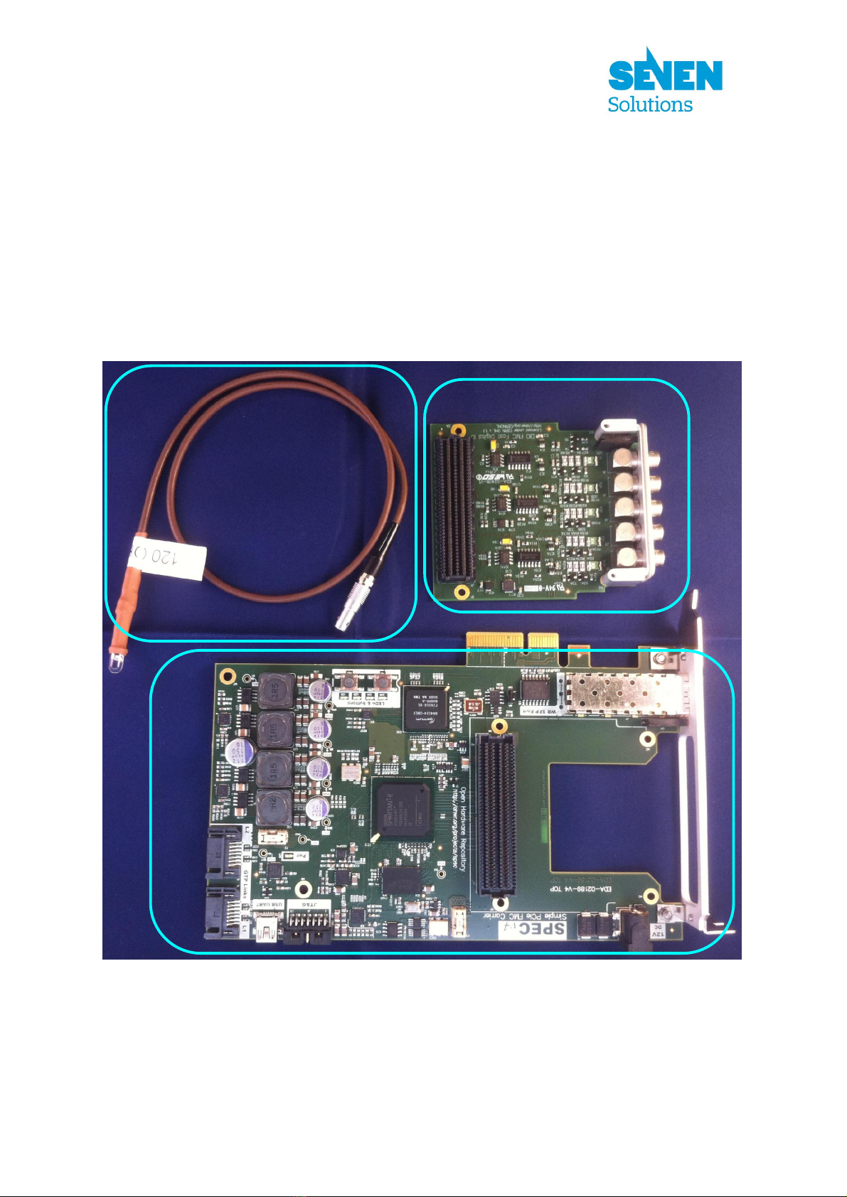
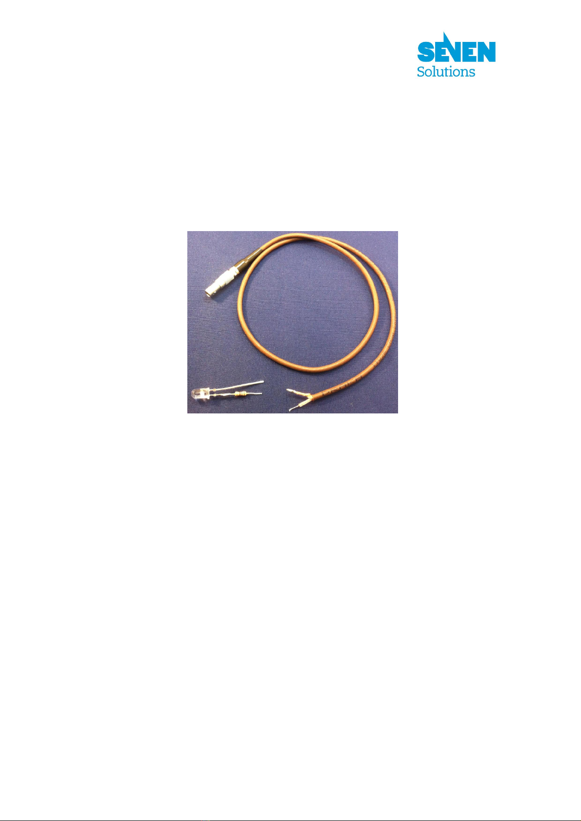
- At least one LEMO 00 test cable (plug and indicator LED attached). The reader is referred to
section 4) for instruction on how to construct this cable.
Figure 1: Specific hardware required
SPEC
FMC
-
DIO
-
5chTTLa
LEMO
-
00 test cable

3/21
b) Software
- Ubuntu Linux with kernel 2.6.38 or higher.
- Python 2.7 or higher.
- The TPS environment installed.
- gnurabbit driver installed.
3) TEST PROCEDURE
a) Hardware installation
Before executing the PTS tests the boards must be properly installed in the computer:
1) Before starting the hardware installation, it is recommended to wear an antistatic wrist band to
avoid electrostatic discharges when handling the boards.
2) Mount the FMC-DIO-5chTTLa board on the FMC connector of the SPEC board as indicated
in Figure 2. The FMC-DIO-5chTTLa board can be mechanically fixed to the SPEC board
using spacers and screws.
Figure 2: FMC-DIO-5chTTLa assembly
4/21
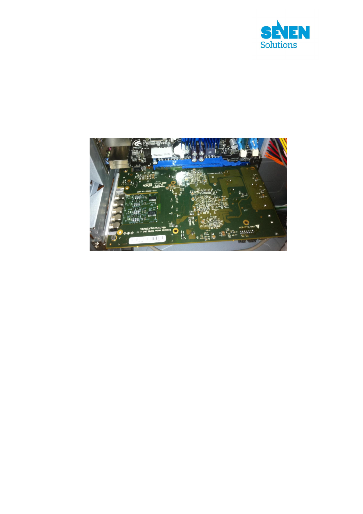
3) Confirm that the computer is switched off (cord unplugged or power-supply switch off) and
plug the assembled SPEC board into a PCIe slot as indicated in Figure 3.
Figure 3: SPEC board inserted into a PCIe slot
4) Switch on the computer and verify that the power LED in the SPEC board is on.
b) PTS execution
Before executing the tests, the TPS environment, a Python interpreter and the gnurabbit driver should
have been previously installed (and the corresponding kernel module loaded). If the module is not
loaded after booting (check it with lsmod), it can be loaded executing:
insmod <pts dir>/gnurabbit/kernel/rawrabbit.ko vendor=0x10dc device=0x18d
See section 2)b)
1) After the computer has finished booting and a user has logged in, open a terminal (if
necessary) and change the current directory to the PTS root directory.
2) Execute: sudo ./fmcdio5chttla.sh

5/21
Next, the program should ask for the serial number of the board. Type the number in the
barcode sticker of the FMC-DIO-5chTTLa board and press enter. The program will ask for an
extra serial number (used in case the manufacturer has a different barcode system). Type the extra
barcode number, or if there is no extra barcode, just press ENTER. The execution of the tests will
start. Refer to the next subsection on how to proceed in each test.
3) Wait for the tests to finish and finally check the results. If any of the tests generated an error or
warning message, it will be displayed in the screen. In case of error, review the whole test
process and repeat the tests one more time for the same board. If during the second execution
of tests you do not get any error or warning messages, it is recommended that you repeat the
tests again with the same initial conditions to ensure that it is not an intermittent problem. If
the error persists, check the log files to obtain detailed information about what occurred during
the execution (see UsersManualProductionTestSuite.pdf), the reader is referred to the
subsection 3)e) in order to elucidate the potential causes of the reported errors
4) Shut down the Linux system and switch off the computer power supply to repeat this process
with another board.
c) List of tests
The test procedure for the FMC-DIO-5chTTLa board is composed of 6 tests summarized in Table 1.
Test
number
Short description User
intervention
00 Check EEPROM and DAC presence and temperature-sensor operation No
01 Check board LEDs (LEDs and LED circuit working) Yes
02 Check board ports as output (port driver, port electrical connectivity and
LVDS-to-LVCMOS IC working)
Yes
03 Check board ports as inputs (DAC and LVDS comparator working) No
04 Check output-enable circuit of board ports No
05 Check termination resistors of board ports No
Table 1: List of tests

6/21
Test00
This test is intended to check the FMC-DIO-5chTTLa-board EEPROM and DAC presence and
temperature-sensor operation
Conditions: To execute this test completely, the FMC-DIO-5chTTLa-board presence line, the I2C
bus and the OneWire bus must work properly.
Procedure details:
- Load SPEC-board firmware (the FPGA is configured using the bit stream contained in the
spec_top.bin file)
- Test mezzanine presence line (check if the FMC-DIO-5chTTLa-board is correctly plugged in the
FMC connector of the SPEC board). The successful completion of this presence test is not decisive,
that is, other errors could result in a wrong presence test outcome.
- Initialize the board and its peripherals
- Check that I2C devices (EEPROM -24AA64T- and DAC -DAC5578-) are present
- Check that OneWire device (temperature sensor -DS18B20-) is present and responds
- Check temperature sensor ID
- Check temperature acquisition.
Test01
This test is intended to check the FMC-DIO-5chTTLa-board LEDs (LED and LED circuit working)
Conditions: To execute this test completely, the FMC-DIO-5chTTLa-board presence line must work
properly.
Procedure details:
- Load SPEC-board firmware (the FPGA is configured using the bit stream contained in the
spec_top.bin file)
- Test mezzanine presence line (check if the FMC-DIO-5chTTLa-board is correctly plugged in the
FMC connector of the SPEC board). The successful completion of this presence test is not decisive,
that is, other errors could result in a wrong presence test outcome.
7/21
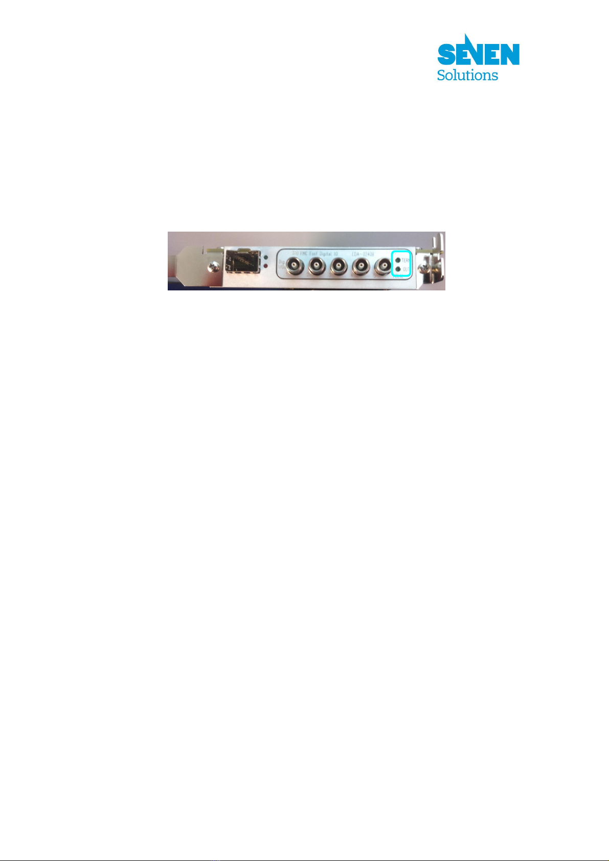
- Alternately blink the two FMC-DIO-5chTTLa-board LEDs.
The user must check that the two LEDs are blinking (see Figure 4) and answer Y (yes) or N (no) to
the program.
Figure 4: FMC-DIO-5chTTLa-board LEDs
Test02
This test is intended to check FMC-DIO-5chTTLa-board ports as output (port driver, port electrical
connectivity and LVDS-to-LVCMOS IC working)
Conditions: To execute this test completely, the FMC-DIO-5chTTLa-board presence line must work
properly.
Procedure details:
- Load SPEC-board firmware (the FPGA is configured using the bit stream contained in the
spec_top.bin file)
- Test mezzanine presence line (check if the FMC-DIO-5chTTLa-board is correctly plugged in the
FMC connector of the SPEC board). The successful completion of this presence test is not decisive,
that is, other errors could result in a wrong presence test outcome.
- Oscillate the state of FMC-DIO-5chTTLa-board ports.
To check the state oscillation of the ports, the user must connect one LEMO-00 test cable (see
subsection 2)a)) to each FMC-DIO-5chTTLa-board port or alternatively connect the same test cable
to each port at least during 2 second when the program requests it as indicated in Figure 5. The user
must check that the cable LED blinks (in all the ports) and then answer Y (yes) or N (no) to the
program.
FMC
-
DIO
-
5chTTLa
-
board LEDs

8/21
Figure 5: LEMO-00 connector plugged in the first FMC-DIO-5chTTLa-board port (port 0)
Test03
This test is intended to check FMC-DIO-5chTTLa-board ports as inputs (DAC and LVDS comparator
working)
Conditions: To execute this test completely, the FMC-DIO-5chTTLa-board ports must work as
outputs (test02 passed) and the I2C bus and the FMC-DIO-5chTTLa-board presence line must work
properly (test00 passed).
Procedure details:
- Load SPEC-board firmware (the FPGA is configured using the bit stream contained in the
spec_top.bin file)
- Test mezzanine presence line (check if the FMC-DIO-5chTTLa-board is correctly plugged in the
FMC connector of the SPEC board). The successful completion of this presence test is not decisive,
that is, other errors could result in a wrong presence test outcome.
- Check the voltage of all ports (by means of the DAC and LVDS comparator) when the port output is
set to 0 and also when it is set to 1.
Test04
This test is intended to check the output-enable circuit of FMC-DIO-5chTTLa-board ports (current-
driver circuit working).
Conditions: To execute this test completely, the FMC-DIO-5chTTLa-board ports must work as
outputs (test02 passed), the I2C bus and the FMC-DIO-5chTTLa-board presence line must work
properly (test00 passed) and the FMC-DIO-5chTTLa-board ports must work as inputs (test03 passed).

9/21
Procedure details:
- Load the SPEC-board firmware (the FPGA is configured using the bit stream contained in the
spec_top.bin file)
- Test mezzanine presence line (check if the FMC-DIO-5chTTLa-board is correctly plugged in the
FMC connector of the SPEC board). The successful completion of this presence test is not decisive,
that is, other errors could result in a wrong presence test outcome.
- Check the voltage of all ports (by means of the DAC and LVDS comparator) when port output is set
to 1 and when port output enable is set to 0.
Test05
This test is intended to check the termination resistors of the FMC-DIO-5chTTLa-board ports
(termination-resistor-activation circuit working).
Conditions: To execute this test completely, the FMC-DIO-5chTTLa-board ports must work as
outputs (test02 passed), the I2C bus and the FMC-DIO-5chTTLa-board presence line must work
properly (test00 passed) and the FMC-DIO-5chTTLa-board ports must work as inputs (test03 passed).
Procedure details:
- Load the SPEC-board firmware (the FPGA is configured using the bit stream contained in the
spec_top.bin file)
- Test mezzanine presence line (Check if the FMC-DIO-5chTTLa-board is correctly plugged in the
FMC connector of the SPEC board). The successful completion of this presence test is not decisive,
that is, other errors could result in a wrong presence test outcome.
- Check the voltage of all ports (by means of the DAC and LVDS comparator) when the port output is
set to 1 and the port termination resistor is enabled.
d) Individual execution of tests
As an alternative, any of the six tests can be executed individually:
1) Follow the first step of subsection 3)b)

10/21
2) Change the current directory to the python directory of FMC-DIO-5chTTLa board in the PTS.
cd <pts dir>/test/fmcdio5chttla/python
3) Execute: sudo ./test0x.py where x is a number in the [0,5] interval. The test results
will be displayed in the screen.
4) Follow steps 3) and 4) of subsection 3)b)
e) Test result message list
This section describes all the potential messages which can be generated during any of the test
execution. These messages can reveal the cause of a test failure.
Error messages
DIOERR00: PRESENT line is not asserted in FMC. Is the fmc-dio-5chttla
correctly inserted into the carrier?
The PRESENT line of the FMC connector is not asserted. This line is used to state that an adequate
board in connected in the FMC connector of the SPEC board (carrier).
Possible causes:
- FMC-DIO-5chTTLa-board is not correctly connected.
- Faulty electrical connectivity in the PRESENT line circuit or FMC connector.
- FPGA configured with an incorrect bit stream file.
DIOERR01: I2C core is not enabled
The internal flags corresponding to the I2C core are not active.
Possible causes:
- FPGA configured with an incorrect bit stream file.
DIOERR02: No I2C device found
No device has responded to any address in the I2C bus.
Possible causes:
- I2C bus is not working properly. Check for short-circuits in any of the bus lines.

11/21
DIOERR03: Device not found. Only x I2C devices found
The DAC or the EEPROM does not respond to their expected address.
Possible causes:
- Wrong address configuration. If the number of devices found (x) is 3, check the list of devices
(addresses) found in the generated log files. For those devices (addresses) which are not listed,
check their address configuration lines (chip soldering and FMC GA0 and GA1 lines
connectivity).
- Faulty electrical connection. If the number of devices found (x) is less than 3, check the list of
devices (addresses) found in the generated log files. For those devices (addresses) which are
not listed, check their I2C lines and power pins (chip soldering).
I2C device EEPROM (24AA64T) at addr 0x50 produced the error: DIOERR04: x
This error message is reserved for future uses.
Possible causes:
- None
I2C device DAC (DAC5578) at addr 0x48 produced the error: DIOERR05: x
The DAC did not respond correctly during the configuration process.
Possible causes:
- An incorrect DAC IC is mounted.
- Defective DAC IC soldering (I2C lines and power-supply pins of DAC).
The message x may give an extra clue about the error cause.
I2C device DAC (DAC5578) at addr 0x48 produced the error: DIOERR06: x
The DAC did not respond correctly to the set-channel voltage commands.
Possible causes:
- An incorrect DAC IC is mounted.
- Defective DAC IC soldering (I2C lines and power-supply pins of DAC).
The message x may give an extra clue about the error cause.
Error in I2C bus. (Addr: x): DIOERR07: Device not initialized
The I2C-device access library has not been properly initialized. This error should never be reported
when executing the original FMC-DIO-5chTTLa-board tests.
Possible causes:
- Test-program programming bug.

12/21
I2C device DAC (DAC5578) at addr 0x48 produced the error: DIOERR08: x
The DAC did not respond correctly to the get channel-voltage configuration commands.
Possible causes:
- An incorrect DAC IC is mounted.
- Defective DAC IC soldering (I2C lines and power-supply pins of DAC).
The message x may give an extra clue about the error cause.
Error in OneWire bus. (Addr: x): DIOERR09: y
The OneWire device DS1820 did not respond correctly during the process for obtaining the chip
unique ID (first commands).
Possible causes:
- An incorrect IC is mounted.
- Defective chip soldering (OneWire line and power-supply pins of DS1820).
- Electrical connectivity problems (short-circuits or open-circuits) in the OneWire line (FMC
connector, OneWire pull-up resistors)
The message y may give an extra clue about the error cause.
Error in OneWire bus. (Addr: x): DIOERR10: Device not initialized
The OneWire-device access library has not been properly initialized. This error should never be
reported when executing the original FMC-DIO-5chTTLa-board tests.
Possible causes:
- Test-program programming bug.
Error in OneWire bus. (Addr: x): DIOERR11: y
The OneWire device DS1820 did not respond correctly during the process for obtaining the
temperature.
Possible causes:
- An incorrect IC is mounted.
- Defective chip soldering (OneWire line and power-supply pins of DS1820).
The message y may give an extra clue about the error cause.
TSTERR00: Operation of fmc-dio-5chttla-board LEDs failed
The user answered “N” indicating that the FMC-DIO-5chTTLa-board LEDs did not operate properly.
Possible causes:
- Soldering problems of the LED circuit (LED, current-limiting resistor, switch transistor).

13/21
- Electrical connectivity problems in the LED activation lines of the FMC connector.
TSTERR01: Operation of fmc-dio-5chttla-board ports as output failed
The user answered “N” indicating that the FMC-DIO-5chTTLa-board ports did not provide the
correct voltage to turn on and off the test-cable LEDs.
Possible causes:
- Soldering problems (short-circuits and open-circuits) of the corresponding LEMO 00
connectors, corresponding lines (fuses) and voltage clamping components (short-circuits).
- Soldering problems of the corresponding port driver IC and the LVDS-to-LVCMOS IC.
- Electrical connectivity problems of the corresponding port control lines of the FMC connector.
Execute test03 to obtain more information which could be useful to isolate the problem.
TSTERR02: Proper voltage reading not obtained in ports: [x] when output
enable=1
Apparently the voltage obtained in the ports x is out of the expected range when the port output is set
to a high or low level. Alternatively, a misleading wrong voltage could have been measured due to a
DAC or comparator operation problem.
Possible causes:
- Something is connected to the LEMO-00 connectors of the ports. Ensure that nothing is
connected to the ports while executing test03.
- Soldering problems (short-circuits) of the corresponding LEMO-00 connectors, corresponding
lines (fuses) and voltage clamping components.
- Soldering problems of the corresponding port driver IC or the LVDS-to-LVCMOS IC.
- Soldering problems of the DAC or the corresponding voltage comparator.
- Electrical connectivity problems of the corresponding port control lines of the FMC connector.
- An incorrect port current-driver IC is mounted.
Check the log files to obtain more information about what caused the error.
Check the results of test02 to isolate the problem.
TSTERR03: Proper voltage reading not obtained in ports: [x] when output
enable=0
Apparently the voltage obtained in the ports x is out of the expected range when the port output is set
to a high level, the termination resistor is disabled and the output-enable circuit is disabled.
Alternatively, a misleading wrong voltage could have been measured due to a DAC or comparator
operation problem.
Possible causes:
- Soldering problems of the corresponding port driver IC or the LVDS-to-LVCMOS IC.
- Soldering problems of the DAC or the corresponding voltage comparator.

14/21
- Electrical connectivity problems of the corresponding port control lines of the FMC connector.
Check the log files to obtain more information about what caused the error.
Check the results of test03 to isolate the problem.
TSTERR04: Proper voltage reading not obtained in ports: [x] when termination
resistors enabled
Apparently the voltage obtained in the ports x is out of the expected range when the port output is set
to a high level and the termination resistor is enabled. Alternatively, a misleading wrong voltage
could have been measured due to a DAC or comparator operation problem.
Possible causes:
- Soldering problems (short-circuits) of the corresponding LEMO-00 connectors, corresponding
lines (fuses) or port input-voltage clamping components.
- Soldering problems of the corresponding port driver IC or the LVDS-to-LVCMOS IC.
- Soldering problems of the DAC or the corresponding voltage comparator.
- Electrical connectivity problems of the corresponding port control lines of the FMC connector.
- An incorrect port current-driver IC is mounted.
Check the log files to obtain more information about what caused the error.
Check the results of test03 to isolate the problem.
Warning messages
TSTWRN00: Strangely-low voltage value obtained in ports: [x] when output=1
Apparently the voltage measured in the ports x is unusually low (but still within the operating range)
when the port output is set to a high level.
Possible causes:
- Something is connected to the LEMO-00 connectors of the ports. Ensure that nothing is
connected to the ports while executing test03.
- Soldering problems of the termination-resistor activation circuit (switching transistor)
- Electrical connectivity problems of the corresponding port termination-resistor control lines of
the FMC connector.
- An incorrect port current-driver IC is mounted.
Check the log files to obtain more information about what caused the error.
TSTWRN01: Strangely-high voltage value obtained in ports: [x] when output=0
Apparently the voltage measured in the ports x is unusually high (but still within the operating range)
when the port output is set to a low level.
Possible causes:

15/21
- Electrical connectivity problems of the corresponding port control lines of the FMC connector.
- An incorrect port current-driver IC is mounted.
Check the log files to obtain more information about what caused the error.
TSTWRN02: Strangely-high voltage value obtained in ports: [x] when output
enable=0
Apparently the voltage measured in the ports x is unusually high (but still within the operating range)
when the port output-enable circuit is disabled.
Possible causes:
- Electrical connectivity problems of the corresponding port control lines of the FMC connector.
- An incorrect port current-driver IC is mounted.
Check the log files to obtain more information about what caused the error.
TSTWRN03: Strangely-low voltage value obtained in ports: [x] when termination
resistors enabled
Apparently the voltage measured in the ports x is unusually low (but still within the operating range)
when the port output is set to a high level and the termination resistor is enabled.
Possible causes:
- Something is connected to the LEMO-00 connectors of the ports. Ensure that nothing is
connected to the ports while executing test05.
- Electrical connectivity problems of the corresponding port termination-resistor control lines of
the FMC connector.
- An incorrect port current-driver IC is mounted.
Check the log files to obtain more information about what caused the error.
TSTWRN04: Strangely-high voltage value obtained in ports: [x] when
termination resistors enabled
Apparently the voltage measured in the ports x is unusually high (but still within the operating range)
when the port output is set to a high level and the termination resistor is enabled.
Possible causes:
- Soldering problems of the termination-resistor activation circuit (switching transistor or
resistors)
- An incorrect port current-driver IC is mounted.
Check the log files to obtain more information about what caused the error.
16/21
4) LEMO 00 TEST CABLE
This section describes how to build the test cable required for test02.
a) Overview
In order to conduct the test02, the user must check that the correct voltage pulses are present in the 5
FMC-DIO-5chTTLa-board ports (LEMO-00 connectors) when this test program is being executed.
This can be achieved using an oscilloscope and measuring the minimum and maximum voltage level
in each port (about 0V and 3.3V respectively). However, a faster and simpler manner is to connect a
LED in series with a 120ohm resistor to each port. To ease this process, the test cable presented in
Figure 1 can be built.
b) List of materials
The main electrical component required to build the test cable are listed in Table 2. Neither the
resistor value nor the LED type is critical. However, the maximum current rating of the FMC-DIO-
5chTTLa-board port driver must not be exceeded. The type of LED has been chosen to have a low
forward voltage drop (about 1.8V). The already assembled 1m cable has been chosen to ease our test
cable building.
Description Manufacturer Manufacturer code RS components
code
Assembled 1m cable with
2 LEMO 00 plugs
Lemo MSB.00.250.LTE100 168-3836
Carbon resistor 0.25W
5% 120ohm axial-lead
RS 707-7599 707-7599
AlGaAs LED 5mm (red) Avago Technologies HLMP-D155 826-509
Table 2: Test-cable component list
17/21
c) Cable building
Cut the assembled 1m LEMO cable and strip off about 2cm of the outer jacket. Cut half of one of the
LED leads and solder the resistor to the remaining part as indicated in Figure 6.
Figure 6: Test-cable building
Solder the LED and resistor to the cable end considering the LED polarity. Isolate the conductors and
optionally cover the union with heat shrink tubing. The resulting cable should be similar to that
presented in Figure 1.
.
Table of contents
Popular Computer Hardware manuals by other brands


Panasonic
Panasonic PanaXSeries MN103S65G user manual

ASROCK
ASROCK PHANTOM GAMING B760M PG LIGHTNING user manual

Avaya
Avaya PARTNER PC CARD installation instructions

BE QUIET!
BE QUIET! PURE ROCK SLIM manual

Enclustra
Enclustra 103 Getting started guide

Abocom
Abocom 802.11b Wireless Short PC Card Wb1500S Specifications