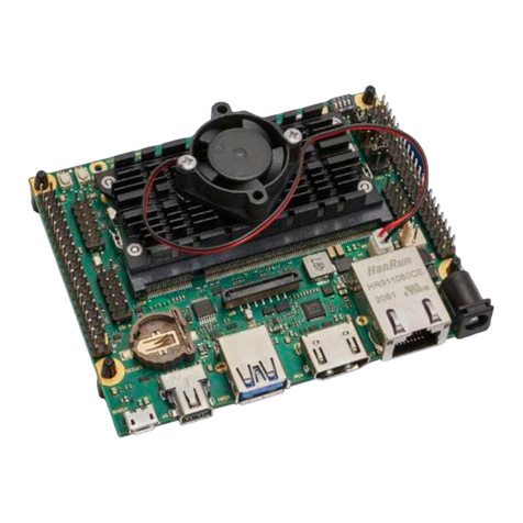
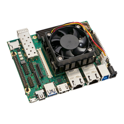
Enclustra 103 User manual

FPGA Manager
Getting Started Guide for FPGA Manager
Ethernet
Purpose
The purpose of this document is to describe how to get started with FPGA Manager.
Product Information Number Name
Product 103 FPGA Manager
Base Development Project 305 Getting Started
Document Information Reference Version Date
Reference / Version / Date D-0000-103-305 01 15.08.2018
Approval Information Name Position Date
Written by MFRE Design Engineer 10.08.2018
Verified by RSTE Technical Expert 14.08.2018
Approved by PMUE VP Marketing 15.08.2018
Enclustra GmbH – Räffelstrasse 28 – CH-8045 Zürich – Switzerland
Phone +41 43 343 39 43 – www.enclustra.com

Copyright Reminder
Copyright 2018 by Enclustra GmbH, Switzerland. All rights are reserved.
Unauthorized duplication of this document, in whole or in part, by any means is prohibited without the prior
written permission of Enclustra GmbH, Switzerland.
Although Enclustra GmbH believes that the information included in this publication is correct as of the date
of publication, Enclustra GmbH reserves the right to make changes at any time without notice.
All information in this document is strictly confidential and may only be published by Enclustra GmbH,
Switzerland.
All referenced trademarks are the property of their respective owners.
Document History
Version Date Author Comment
01 15.08.2018 MFRE Version 01
D-0000-103-305 2 / 23 Version 01, 15.08.2018

Table of Contents
1 Overview 4
1.1 Introduction ................................................ 4
1.2 FPGAManagerEthernet ......................................... 4
1.3 DirectoryStructure ............................................ 4
1.4 Prerequisites ................................................ 5
2 Setup 6
2.1 EssentialInformation ........................................... 6
2.2 HardwareSetup .............................................. 7
2.3 SoftwareSetup............................................... 9
2.3.1 AllPlatforms ................................................ 9
2.3.2 Windows .................................................. 9
2.3.3 Linux..................................................... 10
2.4 FPGABitstreamGeneration ....................................... 11
3 Getting Started 12
3.1 SoftwareprojectC++ ........................................... 12
3.1.1 VisualStudio................................................ 12
3.2 Softwareproject.Net ........................................... 15
3.2.1 VisualStudio................................................ 15
3.3 Runtheexample.............................................. 19
3.3.1 SetIPAddress ............................................... 19
3.3.2 FPGAProgramming............................................ 20
3.3.3 Launchtheapplication .......................................... 20
4 Troubleshooting 22
4.1 VivadoIssues................................................ 22
4.2 JTAGConnectionIssues.......................................... 22
D-0000-103-305 3 / 23 Version 01, 15.08.2018

1 Overview
1.1 Introduction
The FPGA Manager getting started demonstrates how the FPGA Manager is used on a Mercury KX1 FPGA
module in combination with the Enclustra Mercury+ PE1 base board (any board variant) or with the regular
Enclustra Mercury PE1 base board (previous revisions). It presents the basic configuration of the device and
features some example applications.
A troubleshooting section is included at the end of the document, to help the user solve potential issues
related to board connectivity and/or system functionality.
An introduction to the Xilinx tools is provided by the documents below:
•Vivado Design Suite User Guide, Embedded Processor Hardware Design [1]
•Vivado Design Suite Tutorial, Embedded Processor Hardware Design [2]
More information on the Mercury KX1 FPGA module and the Mercury+ PE1 base board can be retrieved
from their respective user manuals [4] [5].
1.2 FPGA Manager Ethernet
The Getting Started Guide for FPGA Manager Ethernet will show the reader how to work with FPGA Manager.
It demonstrates how the FPGA Manager is used to connect the FPGA to the host PC using an Ethernet
connection. Thanks to the great flexibility of FPGA Manager the instruction for the additional interfaces
supported (USB 2.0/3.0 and PCIe) are quiet similar and differ solely in connection used to the host PC. In a
first step the guide will show how the hardware is set up. Secondly it introduces the software required on
the host PC which can be either a Windows or Linux machine. The guide shows the recommended tools,
how to install them and how to create an application.
1.3 Directory Structure
The FPGA Manager is delivered as a ZIP archive file with the following directory structure and contents:
•EN-MGR -interface... — FPGA Project directory for named interface
•SW-EN-MGR -WIN-BIN — Windows software directory
•SW-EN-MGR -LIN-BIN — Linux software directory
•UTIL-EN-MGR -interface... — Software utility for named interface
Depending on the delivery some of the folders may not exist or folders for multiple interfaces are present
D-0000-103-305 4 / 23 Version 01, 15.08.2018

1.4 Prerequisites
•IT
•A computer running either:
•Windows 7 (or later)
•Linux e.g. Ubuntu 16.04
•Software
•Xilinx Vivado 2016.4 WebPack, Evaluation, Design or System Edition (check the Mercury KX1 FPGA
Module User Manual [4] for details on device support in Xilinx tools) with Tri-Mode Ethernet MAC
and Tri-Mode Ethernet MAC Controller licenses (Permanent or Evaluation)
•Enclustra Module Configuration Tool (MCT) [6] (optional1)
•Hardware
•An Enclustra Mercury KX1 FPGA module
•An Enclustra Mercury+ PE1 base board (any board variant) or a regular Mercury PE1 base board
(previous revisions)
•Accessories
•A standard micro USB cable
•An Ethernet cable
Figure 1: FPGA Manager Evaluation Kit
1May be used for flash programming, for FPGA device configuration, Cypress FX3 configuration or for FTDI configuration.
D-0000-103-305 5 / 23 Version 01, 15.08.2018

2 Setup
This section describes the steps required to configure the Mercury KX1 FPGA module and Mercury+ PE1
base board in order to run the example applications. The section includes information on how to:
•Mount the module and configure the base board
•Connect the base board to the host PC
•Install software on the host PC
•Generate the FPGA bitstream
•Create a software application
The example applications, including the expected results of running the software, are described in detail in
Section 3.
2.1 Essential Information
Warning!
Never mount or remove the Mercury KX1 FPGA module to or from the Mercury+ PE1 base board while
the Mercury+ PE1 base board is powered. Always remove or turn off the power supply before mounting
or removing the Mercury KX1 FPGA module.
Warning!
It is possible to mount the Mercury KX1 FPGA module the wrong way round on the Mercury+ PE1 base
board - always check that the mounting holes on the Mercury+ PE1 base board are aligned with the
mounting holes of the Mercury KX1 FPGA module.
The base board and module may be damaged if the module is mounted the wrong way round and
powered up.
Warning!
Depending on the user application, the Mercury KX1 FPGA module may consume more power than can
be dissipated without additional cooling measures; always make sure the FPGA is adequately cooled
by installing a heat sink and/or providing air flow.
Warning!
Please read carefully the Mercury KX1 FPGA module and Mercury+ PE1 base board user manuals
before proceeding.
Note that when Enclustra MCT [6] is used for FPGA configuration or flash programming, all other tools that
may be connected to the FTDI device (e.g. Vivado Hardware Manager, SDK, UART terminal) must be closed.
D-0000-103-305 6 / 23 Version 01, 15.08.2018

2.2 Hardware Setup
Figure 2: Mercury+ PE1 Base Board Assembly Drawing (Top View)
Step Description
1 Set the I/O voltage jumpers on the Mercury+ PE1 base board according to label I/O Voltage in
Figure 2 (the jumpers are marked with red rectangles):
•VSEL A = 3.3 V
•VSEL B = 3.3 V
2 Set the configuration DIP switches on the Mercury+ PE1 base board as follows (see labels CFG A
and CFG B in Figure 2):
•CFG A = [1: OFF, 2: OFF, 3: OFF, 4: ON ]
•CFG B = [1: ON, 2: OFF, 3: ON, 4: ON]
3 Mount the Mercury KX1 FPGA module to the Mercury+ PE1 base board. Make sure that the
mounting holes of the Mercury KX1 FPGA module are aligned with the mounting holes of the
Mercury+ PE1 base board before proceeding.
4 Connect the USB cable between your computer and the Mercury+ PE1 base board. Use the micro
USB port labeled USBUB in Figure 2.
Continued on next page...
D-0000-103-305 7 / 23 Version 01, 15.08.2018

Step Description
5 Connect the 12 V DC power supply plug to the power connector of the Mercury+ PE1 base board
(see label 12 V DC in Figure 2).
6 Set the power switch of the Mercury+ PE1 base board to ON (see label PWR SW in Figure 2).
7 Per default JTAG over USB is used. For this, the FTDI device on the Mercury+ PE1 base board
must be configured to Xilinx JTAG mode using Enclustra MCT [6].
Alternatively, connect the Xilinx Platform Cable USB to the JTAG connector of the Mercury+ PE1
base board (see label JTAG Xilinx in Figure 2).
Details on the Xilinx JTAG mode configuration are presented in the Mercury+ PE1 Base Board
User Manual [5]
8 Use an Ethernet cable to connect the Ethernet port labeled ETH to the host PC
Table 1: Hardware Setup Step-By-Step Guide
Warning!
Please make sure that a single JTAG adapter is connected to the base board and enabled at a given
moment, otherwise the development tools may report errors during JTAG connecting attempts.
D-0000-103-305 8 / 23 Version 01, 15.08.2018

2.3 Software Setup
This chapter gives an overview over the software used in this guide and gives advice how to install it.
2.3.1 All Platforms
Vivado Design Suite
This guide was verified using Vivado 2016.4. The Vivado Design Suite is used to generate the FPGA bitstream
and to download it to the device.
Visit the Xilinx hompage www.xilinx.com for download and install instructions
Note for Windows: If the user does not intend to create the bitstream himself, the Enclustra Module Con-
figuration Tool (MCT) [6] can be used to download the bitstream to the FPGA instead of Vivado
2.3.2 Windows
On Windows the default way described uses Visual Studio
Visual Studio
Step Description
1 Download the Visual Studio 2017 installer (Community, Professional or Enterprise Version)
https://visualstudio.microsoft.com/vs/
2 Start the installer
3 Select the three packets shown in figure 3
4 Wait until the installation is completed
Table 2: Install Visual Studio Step-By-Step Guide
Figure 3: Visual Studio installer
D-0000-103-305 9 / 23 Version 01, 15.08.2018

Visual Studio Code (optional)
Visit https://code.visualstudio.com/ to download the installer and follow the instructions to install
2.3.3 Linux
This guide has been tested on a machine running Ubuntu 16.04
General requirements
Install the packets: lib32gcc1, libc6-i386, lib32z1, lib32stdc++6, lib32ncurses5, lib32gomp1, lib32z1-dev,
g++-multilib
sudo apt i n s t a l l l i b 3 2 g c c 1 l i b c6 −i 38 6 l i b 3 2 z 1 l i b 3 2 s t d c ++6 l i b 3 2 n c u r s e s 5
lib32gomp1 l i b 3 2 z 1 −dev g++−multilib
.NET Core
To install the .NET Core the reader should follow the Microsoft instructions2shown here:
1. Install the packets: liblttng-ust0, libcurl3, libssl1.0.0, libkrb5-3, zlib1g, libicu55
sudo apt i n s t a l l l i b l t t n g −u st0 l i b c u r l 3 l i b s s l 1 . 0 . 0 l i b k r b 5 −3 z l i b 1 g
l i b i c u 5 5
2. Add the microsoft repository
wget −q h t t p s : / / pack ages . m i c r o s o f t . com/ c o n f i g / ubuntu / 1 6 . 0 4 / packages−
microsoft−prod . deb
sudo dpkg −i packages−microsoft−prod . deb
3. Install .NET Core Runtime
sudo apt i n s t a l l apt−transport−https
sudo apt update
sudo apt i n s t a l l aspn etco re−runtime −2.1
4. Install .NET Core SDK
sudo apt i n s t a l l dotnet−sdk −2.1
Visual Studio Code (optional)
Visit https://code.visualstudio.com/ to download the package and install it.
2https://docs.microsoft.com/en-us/dotnet/core/linux-prerequisites?tabs=netcore2x
D-0000-103-305 10 / 23 Version 01, 15.08.2018

2.4 FPGA Bitstream Generation
For a fast start, the pre-generated bitstream included in the binaries directory may alternatively be used,
therefore the steps described in this section may be skipped.
The <base_dir>\vivado_hdl\bitstream directory includes bitstream files for the device included in the
starter kit.
Step Description
1 Start Xilinx Vivado 2016.4 and create the Mercury KX1 FPGA module reference design project:
1. Click on the Tcl console at the bottom of the page and type:
(a) cd <base_dir>/EN_MGR_<interface>_.../vivado_bd (<base_dir> is the direc-
tory in which you extracted the archive contents). Note that you must use /for hier-
archy separator, instead of \.
(b) source scripts/create_project_1.tcl
2. Wait for completion
2 Select your configuration and mode
1. Open param_en_mgr_<interface>.tcl
2. Select mode:
constant ParameterSet_c : string := "MIN_RESOURCES";
or
constant ParameterSet_c : string := "MAX_PERFORMANCE";
3. Open the block design
4. Apply the settings using the tcl console: source param_en_mgr_<interface>.tcl
5. Wait for completion
3 Run Synthesis, Implementation & Bitstream Generation in Vivado 2016.4:
1. Click on Generate Bitstream from the Flow Navigator bar
2. In the Launch Runs window click OK - this will start automatically the entire implementation
process
3. Wait for completion →select View Reports →OK
Table 3: FPGA Bitstream Generation Step-By-Step Guide
D-0000-103-305 11 / 23 Version 01, 15.08.2018

3 Getting Started
This chapter describes step by step how a simple application of FPGA Manager is created and executed.
Please follow the setup instruction of chapter 2 before continuing.
3.1 Softwareproject C++
3.1.1 Visual Studio
Step Description
1 Start Visual Studio
2 Create a new Project
1. Click on File →New →Project
2. Select Visual C++
3. Select Windows Console Application
4. Name the Project
5. Choose a location for the project
6. Click OK
The Configuration is shown in Figure 4
3 Add NuGet package source
Note: This step only has to be done for the first project
1. Click on Tools →NuGetPackageManager →Package Manager Settings
2. Click on Package Sources on the Left
3. Click Add (green plus symbol)
4. Give the new package source a name: e.g. ’Enclustra’
5. For Source field hit ... and browse for the NuGet folder
6. Click on Update
7. Click on OK
The steps are marked in Figure 5
4 Install the NuGet Package
1. Click on Tools →NuGetPackageManager →Manage NuGet Packages for Solution
2. On the top left click Browse
3. On the top right of the window in Package source
(a) Select ‘Enclustra‘ (or what ever name has been chosen during step 3)
4. Select Enclustra.FPGAManager.ApiCpp
5. Tick the project in the list on the right
6. Hit install →OK
The installation step are shown in Figure 6
5 Set project properties
1. Click on Project →Properties
2. Select NuGet Dependencies →FPGA Manager
3. Set the FPGA Manager Linkage value to Dynamic (DLL) as shown in Figure 7
4. Hit OK
Continued on next page...
D-0000-103-305 12 / 23 Version 01, 15.08.2018

Step Description
6 Writing a basic application to Read out the software version and a demo register
1. Open a connection to the target FPGA device
2. Read the software version
3. Readout the value of a memory mapped register
The code for these steps is shown in the listing 1
Table 4: Visual Studio Step-By-Step Guide
Figure 4: Setup Cpp project
Figure 5: Add NuGet Source
D-0000-103-305 13 / 23 Version 01, 15.08.2018

Listing 1: C++ Hello world Example
#include "stdafx.h"
#include "FpgaManager.h"
#include <iostream>
namespace fpgamgr =enclustra:: fpgamanager;
int main()
{
// Creating Object
fpgamgr:: FpgaManager mgr(fpgamgr::types::ApiUrl::UDP("192.168.33.12"));
// Read software version
std :: cout << "FPGA Manager Version : " << mgr.Details() << std::endl;
// Creating a Memorymapped acces to Stream 0
auto&mm =mgr.CreateMemoryMap(0);
// Open Stream 0
mgr .Open();
// Read the register value
std :: cout << " Register: " << std::hex << mm.ReadRegister(0 x10001000) << std :: endl;
getchar();
return 0;
}
3.2 Softwareproject .Net
3.2.1 Visual Studio
Step Description
1 Start Visual Studio
2 Create a new Project
1. Click on File →New →Project
2. Select Visual C# →Windows Classic Desktop
3. Select Console App (.NET Framework)
4. Name the Project
5. Choose a location for the project
6. Click OK
The Configuration is shown in Figure 8
3 Add NuGet package source
Note: This step only has to be done for the first project
1. Click on Tools →NuGetPackageManager →Package Manager Settings
2. Click on Package Sources on the Left
3. Click Add (green plus symbol)
4. Give the new package source a name: e.g. ’Enclustra’
5. For Source field hit ... and browse for the NuGet folder
6. Click on Update
7. Click on OK
The steps are marked in Figure 9
Continued on next page...
D-0000-103-305 15 / 23 Version 01, 15.08.2018

Step Description
4 Install the NuGet Package
1. Click on Tools →NuGetPackageManager →Manage NuGet Packages for Solution
2. On the top left click Browse
3. On the top right of the window in Package source
(a) Select ‘Enclustra‘ (or what ever name has been chosen during step 3)
4. Select Enclustra.FPGAManager.ApiDotNet
5. Tick the project in the list on the right
6. Hit install →OK
The installation step are shown in Figure 10
5 Set project properties
1. Click on Build →Configuration Manager
2. Drop down Active solution platform →<new>
(a) Type or select the new platform →x64
(b) Leave Copy settings from on Any CPU
(c) Hit OK
3. In the Project context, drop down Platform
(a) Select <new>
(b) New platform →x64
(c) Leave Copy settings from on Any CPU
(d) Hit OK
4. Change Active solution configuration to Release
5. Select for the Platform →x64 again, as shown in Figure 11
6 Writing a basic application to Read out the software version and a demo register
1. Open a connection to the target FPGA device
2. Read the software version
3. Readout the value of a memory mapped register
The code for these steps is shown in the listing 1
Table 5: Visual Studio .NET project Step-By-Step Guide
D-0000-103-305 16 / 23 Version 01, 15.08.2018

Figure 10: Install FPGA Manager .Net package
Figure 11: Change Build settings
Listing 2: C# dotNet Hello world Example
namespace DemonstrateHelloWorld
{
using System;
using FPGAMgr =Enclustra.FPGAManager;
class Program
{
static void Main(string[] args)
{
using (var mgr =new FPGAMgr.FpgaManagerApi(FPGAMgr.ApiUrl.UDP("192.168.33.12")))
{
Console.WriteLine($"FPGA Manager Version: {mgr. Details. BaseDllVersion } /
{mgr. Details. ApiDllVersion }");
var memory =mgr.CreateMemoryMap(0);
mgr .Open();
var registerValue =memory.ReadRegister(0 x10001000);
Console.WriteLine($"Read {registerValue:X8} from register ");
Console.ReadKey();
}
}
}
}
D-0000-103-305 18 / 23 Version 01, 15.08.2018

3.3 Run the example
Follow the steps below in the given order
3.3.1 Set IP Address
As described in section 2.2 the FPGA Module is connected to the PC over Ethernet. To be able to establish
a connection the ip address has to be set.
On Windows
Step Description
1 Open Control Panel →Network and Internet →Network and Sharing Center
1 Click on the Local Area Connection →Properties (see Figure 12)
1. Click on Internet Protocol Version 4 (TCP/IPv4) →Properties
(a) Set the IP address to 192.168.33.1
(b) Set the subnet mask to 255.255.255.0
(c) Hit OK
Table 6: Computer Network Setup Step-By-Step Guide
Figure 12: Network Adapter Configuration for FpgaManger demo
On Linux
Open a terminal and set the ip address, replace <interface> with the name of the interface connected or
use the network manager GUI to set the IPv4 address.
sudo i f c o n f i g < i n t e r f a c e > 1 9 2 . 1 6 8 . 3 3 . 1 netmask 2 5 5 : 2 5 5 : 2 5 5 . 0
D-0000-103-305 19 / 23 Version 01, 15.08.2018

3.3.2 FPGA Programming
Step Description
1 Open Vivado 2016.4:
1. Click on Flow →Open Hardware Manager
2. Click Open Target
3. On the left, the device should be shown, click right on the device ‘xc7k160‘ and select
Program Device as shown in Figure 13.
4. For Bitstream file hit ... →Browse to the Bistream and press ok
•The pre-build bitstream can be found <path_to_dir>/EN-MGR-ETH1G-.../vivado_
hdl/bitstream/, select either MIN_RESOURCES.bit or MAX_PERFORMANCE.bit
•A bitstream generated with Vivado can be found <path_to_vivado_proj>
/<project>.runs/impl_1/en_mgr_xil_x7_kx1_pe1.bit
5. Hit Program
2 After the FPGA is successfully configured, the DONE LED on the Mercury+ PE1 base board should
be lit. The LED 3 on the module Mercury KX1 FPGA module should start blinking
Table 7: FPGA Programming Step-By-Step Guide
Figure 13: Select the Device to program
D-0000-103-305 20 / 23 Version 01, 15.08.2018
Table of contents
Other Enclustra Computer Hardware manuals
Popular Computer Hardware manuals by other brands
Addonics Technologies
Addonics Technologies ADPEXC manual

Dolby Laboratories
Dolby Laboratories DA20 installation manual

Panasonic
Panasonic PAW-SERVER-PKEA-1 installation instructions
Aprotech
Aprotech INTEL CORE i5 SYSTEM BOARD user manual
NXP Semiconductors
NXP Semiconductors PCA9555 Product data sheet
CAMBRIONIX
CAMBRIONIX PP15S user manual


