Severn Trent VAX4600 Series User manual

- 1 - 115.6001.10
Instruction Manual — Vaporizer
for Chlorine or Sulfur Dioxide
Series VAX4600
CAPITAL CONTROLS

115.6001.10 - 2 -
Theseinstructionsdescribetheinstallation,operationandmaintenanceofthesubjectequipment. Failuretostrictlyfollow
these instructions can lead to an equipment rupture that may cause significant property damage, severe personal injury
and even death. If you do not understand these instructions, please call Severn Trent Water Purification for clarification
beforecommencinganyworkat215-997-4000 and ask for a Field Service Manager.SevernTrentWaterPurification,Inc.
reserves the rights to make engineering refinements that may not be described herein. It is the responsibility of the
installer to contact Severn Trent Water Purification, Inc. for information that cannot be answered specifically by these
instructions.
Any customer request to alter or reduce the design safeguards incorporated into Severn Trent Water Purification
equipment is conditioned on the customer absolving Severn Trent Water Purification from any consequences of
such a decision.
SevernTrent Water Purificationhasdeveloped the recommendedinstallation,operating and maintenance procedureswith
careful attention to safety. In addition to instruction/operating manuals, all instructions given on labels or attached tags
should be followed. Regardless of these efforts, it is not possible to eliminate all hazards from the equipment or foresee
every possible hazard that may occur. It is the responsibility of the installer to ensure that the recommended installation
instructions are followed. It is the responsibility of the user to ensure that the recommended operating and maintenance
instructions are followed. Severn Trent Water Purification, Inc. cannot be responsible deviations from the recommended
instructions that may result in a hazardous or unsafe condition.
SevernTrent WaterPurification,Inc. cannotberesponsible for theoverallsystem designofwhich our equipmentmaybe an
integral part of or any unauthorized modifications to the equipment made by any party other that Severn Trent Water
Purification,Inc.
Severn Trent Water Purification, Inc. takes all reasonable precautions in packaging the equipment to prevent shipping
damage. Carefullyinspecteachitem andreport damagesimmediatelytotheshipping agentinvolved forequipmentshipped
“F.O.B. Colmar” or to Severn Trent Water Purification for equipment shipped “F.O.B Jobsite”. Do not install damaged
equipment.
SEVERNTRENT SERVICES,COLMAROPERATIONS
COLMAR,PENNSYLVANIA,USA
IS ISO 9001: 2000 CERTIFIED

- 3 - 115.6001.10
Table of Contents
1 INTRODUCTION . . . . . . . . . . . . . . . . . . . . . . . . . . . . . . . . . . . . . . . . . . . . . . . . . . . . . . . . . . . . . . . . . . . . . . . . . 5
1.1 General . . . . . . . . . . . . . . . . . . . . . . . . . . . . . . . . . . . . . . . . . . . . . . . . . . . . . . . . . . . . . . . . . . . . . . . . . . 5
1.2 ComponentDescription . . . . . . . . . . . . . . . . . . . . . . . . . . . . . . . . . . . . . . . . . . . . . . . . . . . . . . . . . . . . . . 6
1.3 Specifications . . . . . . . . . . . . . . . . . . . . . . . . . . . . . . . . . . . . . . . . . . . . . . . . . . . . . . . . . . . . . . . . . . . . . 8
1.4 Principle ofOperation . . . . . . . . . . . . . . . . . . . . . . . . . . . . . . . . . . . . . . . . . . . . . . . . . . . . . . . . . . . . . . . 10
2 INSTALLATION . . . . . . . . . . . . . . . . . . . . . . . . . . . . . . . . . . . . . . . . . . . . . . . . . . . . . . . . . . . . . . . . . . . . . . . . 11
2.1 Location . . . . . . . . . . . . . . . . . . . . . . . . . . . . . . . . . . . . . . . . . . . . . . . . . . . . . . . . . . . . . . . . . . . . . . . . . 11
2.2 Mounting . . . . . . . . . . . . . . . . . . . . . . . . . . . . . . . . . . . . . . . . . . . . . . . . . . . . . . . . . . . . . . . . . . . . . . . . . 11
2.3 Piping . . . . . . . . . . . . . . . . . . . . . . . . . . . . . . . . . . . . . . . . . . . . . . . . . . . . . . . . . . . . . . . . . . . . . . . . 12
2.4 Wiring . . . . . . . . . . . . . . . . . . . . . . . . . . . . . . . . . . . . . . . . . . . . . . . . . . . . . . . . . . . . . . . . . . . . . . . . . 14
3 OPERATION . . . . . . . . . . . . . . . . . . . . . . . . . . . . . . . . . . . . . . . . . . . . . . . . . . . . . . . . . . . . . . . . . . . . . . . . . . . 16
3.1 General . . . . . . . . . . . . . . . . . . . . . . . . . . . . . . . . . . . . . . . . . . . . . . . . . . . . . . . . . . . . . . . . . . . . . . . . . 16
3.2 Pre-StartupComponents . . . . . . . . . . . . . . . . . . . . . . . . . . . . . . . . . . . . . . . . . . . . . . . . . . . . . . . . . . . . 16
3.3 Startup . . . . . . . . . . . . . . . . . . . . . . . . . . . . . . . . . . . . . . . . . . . . . . . . . . . . . . . . . . . . . . . . . . . . . . . . . 16
3.4 Calibration . . . . . . . . . . . . . . . . . . . . . . . . . . . . . . . . . . . . . . . . . . . . . . . . . . . . . . . . . . . . . . . . . . . . . . . . 19
4 SERVICE . . . . . . . . . . . . . . . . . . . . . . . . . . . . . . . . . . . . . . . . . . . . . . . . . . . . . . . . . . . . . . . . . . . . . . . . . . . . . . 20
4.1 Changing ChemicalSupply . . . . . . . . . . . . . . . . . . . . . . . . . . . . . . . . . . . . . . . . . . . . . . . . . . . . . . . . . . . 20
4.2 Cleaning . . . . . . . . . . . . . . . . . . . . . . . . . . . . . . . . . . . . . . . . . . . . . . . . . . . . . . . . . . . . . . . . . . . . . . . . . 20
4.3 HeaterReplacement . . . . . . . . . . . . . . . . . . . . . . . . . . . . . . . . . . . . . . . . . . . . . . . . . . . . . . . . . . . . . . . . 21
4.4 Water Filling . . . . . . . . . . . . . . . . . . . . . . . . . . . . . . . . . . . . . . . . . . . . . . . . . . . . . . . . . . . . . . . . . . . . . . 22
4.5 LowWaterLevelAlarmand CutoffSwitch . . . . . . . . . . . . . . . . . . . . . . . . . . . . . . . . . . . . . . . . . . . . . . . . 23
4.6 WaterTemperatureControlThermostat . . . . . . . . . . . . . . . . . . . . . . . . . . . . . . . . . . . . . . . . . . . . . . . . . . 23
4.7 Highand Low WaterTemperatureAlarm Switches. . . . . . . . . . . . . . . . . . . . . . . . . . . . . . . . . . . . . . . . . 23
4.8 CathodicProtection-AnodeReplacement . . . . . . . . . . . . . . . . . . . . . . . . . . . . . . . . . . . . . . . . . . . . . . . 23
4.9 RecommendedTorqueValues . . . . . . . . . . . . . . . . . . . . . . . . . . . . . . . . . . . . . . . . . . . . . . . . . . . . . . . . . 25
5 TROUBLESHOOTINGCHART . . . . . . . . . . . . . . . . . . . . . . . . . . . . . . . . . . . . . . . . . . . . . . . . . . . . . . . . . . . . . . 25
CERTIFICATEOF CONFORMITY . . . . . . . . . . . . . . . . . . . . . . . . . . . . . . . . . . . . . . . . . . . . . . . . . . . . . . . . . . . 27
FIGURES
1 VaporizerFlow Diagram. . . . . . . . . . . . . . . . . . . . . . . . . . . . . . . . . . . . . . . . . . . . . . . . . . . . . . . . . . . . . . . 6
2 Chemical Boiling Points at System Pressure . . . . . . . . . . . . . . . . . . . . . . . . . . . . . . . . . . . . . . . . . . . . . . 7
3 CathodicProtection Wiring . . . . . . . . . . . . . . . . . . . . . . . . . . . . . . . . . . . . . . . . . . . . . . . . . . . . . . . . . . . . 7
4 CabinetDimensions & Utility Connection Locations . . . . . . . . . . . . . . . . . . . . . . . . . . . . . . . . . . . . . . . . . 9
5 CabinetDimensions and Utility Locations . . . . . . . . . . . . . . . . . . . . . . . . . . . . . . . . . . . . . . . . . . . . . . . . 11
6 VaporizerPipingConnections . . . . . . . . . . . . . . . . . . . . . . . . . . . . . . . . . . . . . . . . . . . . . . . . . . . . . . . . 12
7 Typical ManifoldPiping . . . . . . . . . . . . . . . . . . . . . . . . . . . . . . . . . . . . . . . . . . . . . . . . . . . . . . . . . . . . . . 13
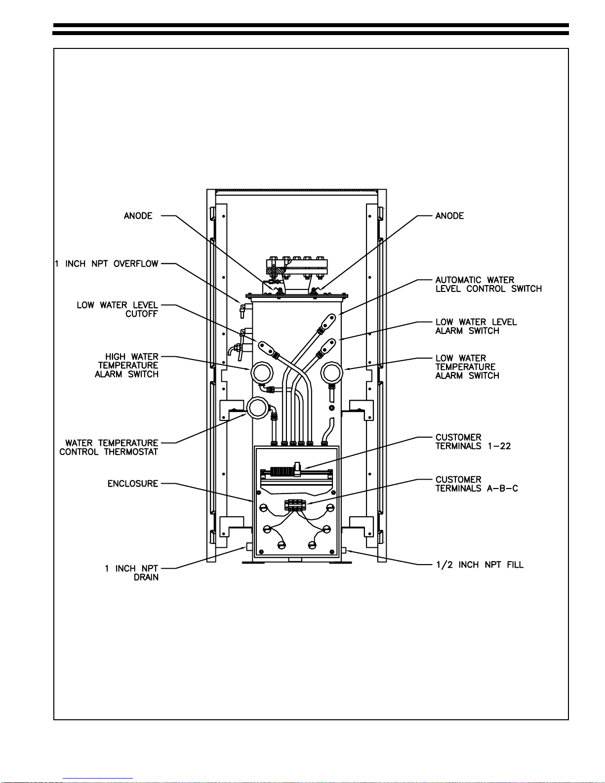
8 Chlorineand SulfurDioxideVaporizer Components . . . . . . . . . . . . . . . . . . . . . . . . . . . . . . . . . . . . . . . . . 17
9 Disassemblyand Cleaning ofChamberComponents. . . . . . . . . . . . . . . . . . . . . . . . . . . . . . . . . . . . . . . . 22
10 ReplacingHeater Element . . . . . . . . . . . . . . . . . . . . . . . . . . . . . . . . . . . . . . . . . . . . . . . . . . . . . . . . . . . . 24

115.6001.10 - 4 -

- 5 - 115.6001.10
1 INTRODUCTION
1.1 General
Process chemicals like chlorine or sulfur dioxide, are available as a liquid, but are normally fed as a gas, and
may be fed directly from their storage container (cylinder or ton container) provided each liquid’s vaporizing
requirements do not exceed the container’s maximum vaporization rate. When large quantities of gaseous
chemical are required, a liquid chemical vaporizer may be used. The vaporizer does not increase or
decrease the pressure of the chemical being vaporized., but changes its state from liquid to gas.
NOTE: The following documents are referenced within this instruction manual:
115.3002 - Vaporizer Piping Connections
115.3003 - Typical manifold Piping for Vaporizers
115.3004 - Vaporizer Pressure Relief Piping With Rupture Disc
115-3005 - Expansion Chamber Assembly
115-3006 Vaporizer Components
115.3020 - Vaporizer Control Circuit Wiring Diagram, 120 Vac
115.3021 - Vaporizer Control Circuit Wiring Diagram, 240 Vac
115.3024 - Vaporizer Heater Circuit, 208, 240 & 575 Vac, 3 phase
115.3025 - Vaporizer Heater Circuit, 380 & 480 Vac, 3 phase
115.6010 - Gas Pressure Reducing Valve, ADVANCE Series 861 Instruction Manual
115.6020 - Gas Pressure Relief Valve and Rupture Disc Instruction Manual
1.2 Component Description
Series VAX4600 Vaporizer utilizes an electrically heated water bath to add the necessary heat to the liquid
chemical for vaporization. The unit consists of a hot water tank, a chemical vaporizing chamber, a NEMA 4X
heater control circuit, a NEMA 4X water level control circuit, chemical and hot water monitoring instruments,
cathodic protection circuit, and ABS structural foam enclosure.
NOTE: The standard vaporizer is not recommended for outside, unprotected installations.
1.2.1 Water Tank
The water tank is constructed of corrosion-resistant welded stainless steel. It houses six electric
water heaters and all water condition sensing and control devices (e.g. water level, water
temperature) in a standard NEMA 4X design.
1.2.2 Chemical Vaporizing Chamber
The chamber is constructed of 6" Schedule 80 steel pipe. Its all-welded construction conforms to
ASME codes for unfired pressure vessels. Externally mounted fins are utilized to aid in the efficient
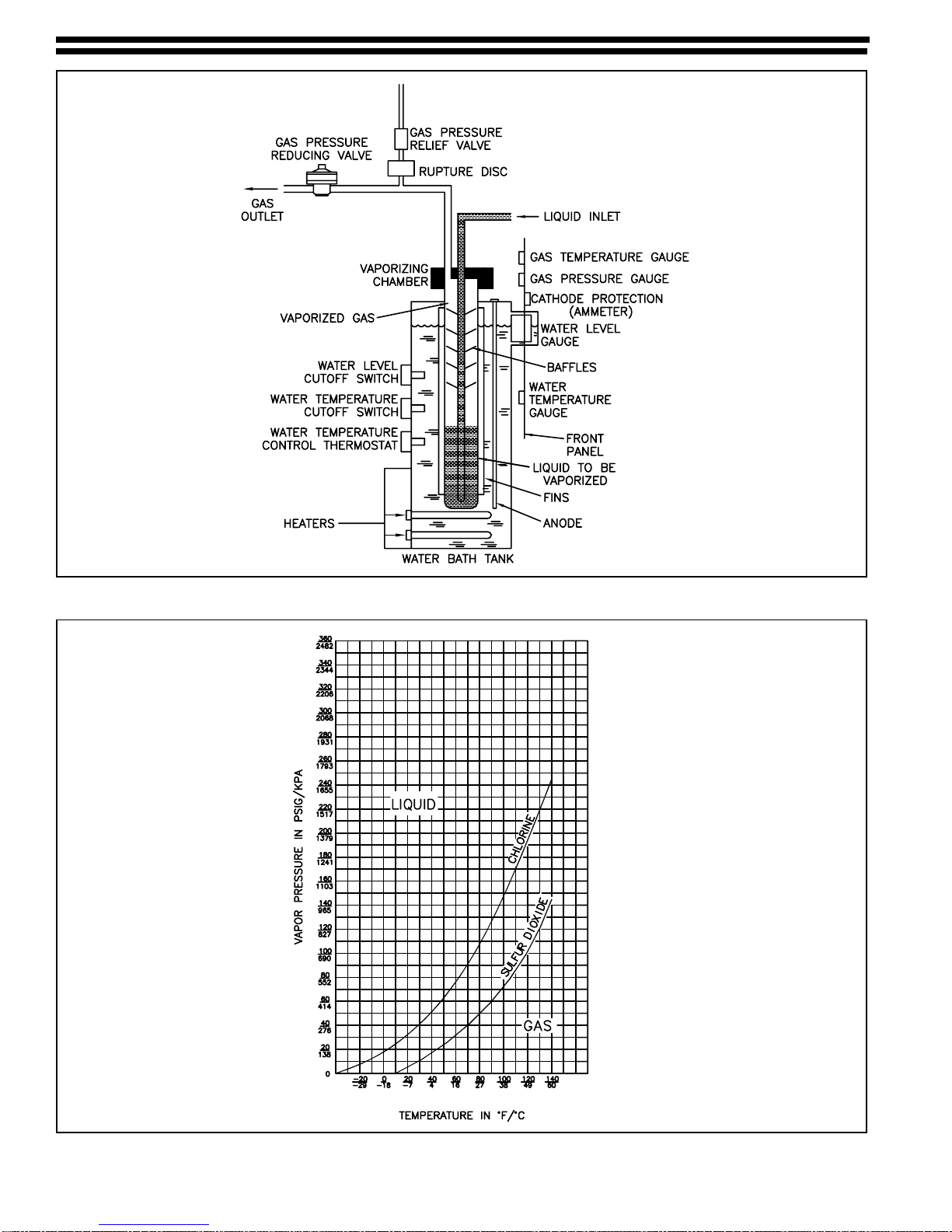
transfer of heat from the water bath to the liquid chemical. Internally mounted baffles aid in
superheating of the chemical vapors and dropping out entrained liquid droplets as they rise from the
liquid level to the vaporizer discharge. See Figure 1
The vaporizing chamber also houses the chemical monitoring sensors for temperature and pressure.
NOTE: Superheatistheincreaseinthegastemperatureabovetheboilingpointatagivenpressure
(minimum10°F[5.5°C]aboveboilingpoint),andisrequiredtopreventthegasfromreliquefyingasit
flows in the system. See Figure 2 for boiling points. Heat tracing and/or insulation of gas pressure
piping is recommended to maintain superheat. Loss of superheat may cause reliquefaction and
subsequent damage to the gas feeder.
115.6001.10 - 6 -
Figure 1 - Vaporizer Flow Diagram
Figure 2 - Chemical Boiling Points at System Pressure

- 7 - 115.6001.10
1.2.3 Control Circuits (Refer to Bulletins 115.3024 and 115.3025)
a. Heater Control
The heater circuit is supplied wired to accommodate one of the following source voltages 240, 480,
or575Vac,50/60 Hz, 3 phase (other voltages or single phase aresuppliedoptionally).The heaters
arecontrolledby a tank mounted electrically operated, field- adjustablethermostat which controls
theheatermagneticcontactor(relay)toregulatewaterbathtemperature.Themagneticcontactor
and safety switch are wall mounted, but optionally may be installed on the rear of the water tank.
b. WaterLevel Control (Refer toBulletins115.3020 or 115.3021)
Thewater level control circuit consists of a lowwater level cutoff switch, a low waterlevel alarm
switch, and a water level control switch. The low water level cutoff switch is wired in series with the
heater control circuit to prevent actuation of heaters when there is a low or no water condition.
Thewaterlevelcontrolswitchisfieldwiredtoasolenoidvalveinthewatersupplylineproviding
automaticwater level control. The low water level alarm switch may be field wiredto a light or horn
towarnofalowwaterlevelcondition.
1.2.4 MonitoringInstruments
Allmonitoringinstrumentsarepanelmountedonthefrontofthevaporizer(seefrontcover).Theyconsist
ofthechemicalpressureandtemperaturegauges (used to determine gas superheat utilizing Figure 2),
thewaterlevel sight glass, the water temperature gauge, and the cathodic protectionammeterwith
adjustmentpotentiometer.
1.2.5 Cathodic Protection (See Figure 3)
Thiscircuitisdesignedtoprevent electrolytic degradation of the water tank and vaporization chamber. It
utilizes two sacrificial magnesium anodes, a milliammeter to indicate current flow and a potentiometer
to adjust the electrolytic current. The anodes will dissolve to provide an electrolytically stable water
tank. A zero or low current reading on the ammeter at all potentiometer settings indicates a need to
replacethe anodes.
Figure 3 - Cathodic Protection Wiring
115.6001.10 - 8 -
1.2.6 Corrosion Resistant Enclosure (See Figure 4)
The enclosure consists of six pieces; a bottom and a top, two sides and a front and back bezel. The
bezels are pressure-formed ABS and the sides, top and bottom are structural foam plastic. Easy
removalofthefrontbezelexposesallcontrolandmonitoringcomponents.Thebackbezelisprovidedfor
safecoveringof all control components and magnetic contactor. The enclosure iseasilycleaned with
anyhouseholdcleanerand a damp cloth.
1.3 Specifications
1.3.1 Electrical Requirements:
Voltage: 240, 380, 480, 575 Vac, 50/60 Hz, 1 or 3 phase
PowerConsumption:Heaterwattage is based on the maximum vaporization requirements of the unit.
SeeTable I.
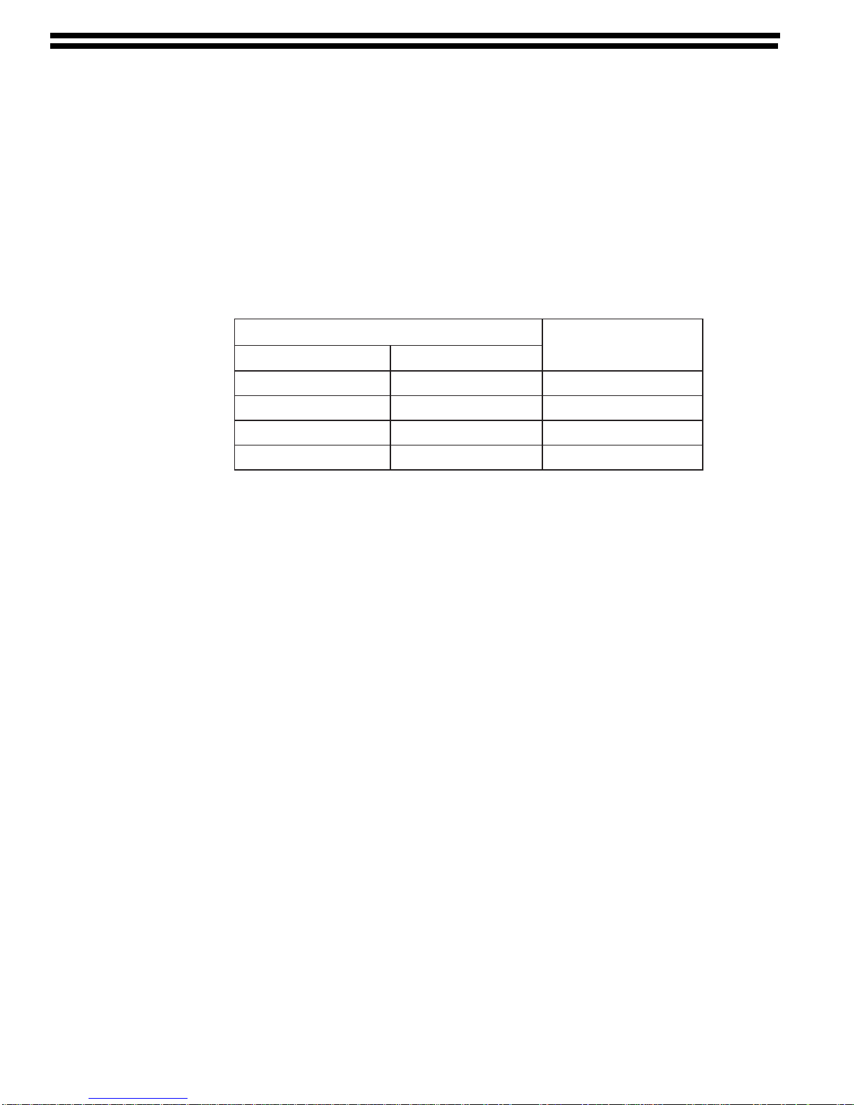
Table I - Capacities/Heater Wattage
Notes:
1. All internal heater wiring is sized per NEC requirements.
2. Each chemical has different rates of vaporization, resulting in the capacities listed in Table I.
3. Control Circuit Voltage-120 Vac, 60 Hz or 240 Vac, 50 Hz
4.Control Circuit Power Consumption - The vaporizer is supplied with dry contacts as standard. Field
attachedindicators(horns,lights,etc.)varyinpowerconsumption,therefore,refertothemanufacturer’s
specificationsforspecificwattageusage.
NOTE:Seenoteon115.3020 and 115.3021 regarding current ratings of contacts when used to directly
power indicators. A 10 amp fuse is recommended to protect this circuit.
1.3.2 Mechanical Requirements:
Chamber - The gas vaporization chamber is manufactured from 6" ASTM SA-53-B seamless carbon
steel pipe. All welds are in accordance with ASME boiler and pressured vessel codes, Section VIII,
Division I. Both inlet and outlet connections are 1" NPTF.
Tank - The water tank is constructed of stainless steel and holds a minimum of 37 gallons (140 liters)
of water. PVC foam 1/2" (13 mm) thick surrounds all exterior surfaces to insulate from excessive
heat loss.
Pressure Reducing Valve -See Bulletins 115.6010 and 115.3011
Pressure Relief Valve - The relief valve is designed to relieve at 250 psig (1700 kPa/17 bar). It is
mounted downstream of a rupture disc assembly which is designed to rupture at 250 psig (1700 kPa/
17 bar). An optional pressure switch or gauge may be installed between the relief valve and rupture
disc to indicate a ruptured disc condition. (See Bulletin 115.6020)
Liquid Expansion Chamber - The expansion chamber is designed to permit a gaseous “air" pad in the
liquidlinetopreventexcessiveover pressure in the liquid line. It is mounted downstream of a rupture
disc assembly designed to rupture at 400 psig (2760 kPa/27 bar). An optional pressure switch or gauge
maybe installed between the rupture disc and expansionchamber to indicate a ruptured condition
(Figure14).ThechamberconformstoD.O.T.Spec.3AA1800.SeeBulletin115.3005.
yticapaC egattaWretaeHlatoT
enirolhCedixoiDrufluS
)h/gk57(DPP0004)h/gk06(DPP0003Wk9
)h/gk021(DPP0006)h/gk58(D
PP0054Wk21
)h/gk051(DPP0008)h/gk0511(0006Wk51
)h/gk002(DPP000,01)h/gk041(0057Wk81
- 9 - 115.6001.10
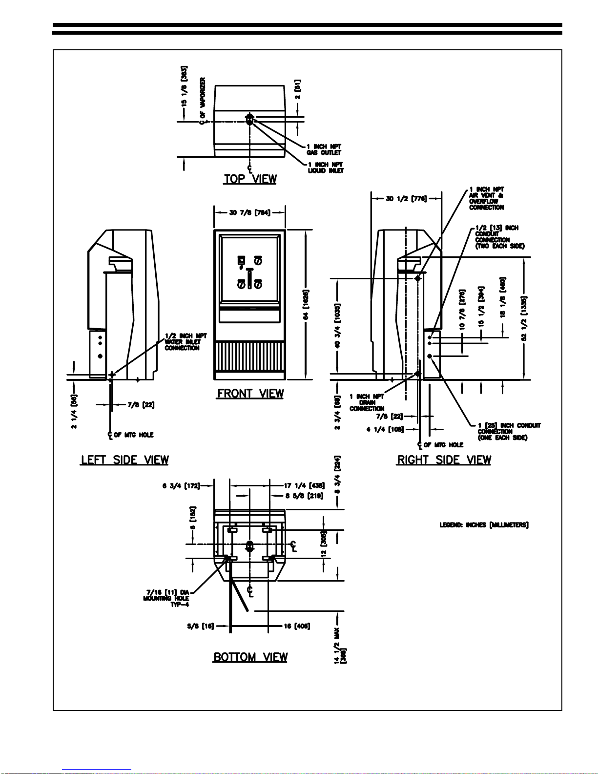
Figure 4 - Cabinet Dimensions & Utility Connection Locations

115.6001.10 - 10 -
1.3.3 Operating Pressure
Vaporizer:
Minimum: 45 psi
Normal: 100 psi
Maximumallowable working pressure:666psi @ 212°F (however, rupture disk will ruptureat
275 psi)
The vaporizer chamber is stamped with a U and W-L stamp which means it is arc or gas welded and
for lethal service.
1.3.4 EMC Testing
The vaporizer has been evaluated for RF interference over a frequency range of 80-1000 MHZ and
showed overall acceptable immunity. However, it may show a low level of susceptibility to radio
frequency emissions as listed below. Additionally, no interference will be seen unless the intensity of
field strength at these frequencies exceeds 2.3 volts/meter.
Frequencies (MHZ)
180-200 420-465
207-210 563-570
367-380 684-701
380-405 738-746
Interferenceof any duration will not effectthevaporizer’sperformanceunsafely at any frequency.
Intermittentoperation under conditions of RF interference will not effect the instrument’s operation
irreversibly. Prolonged operation under conditions of RF interference, though not unsafe, may
damage some instrument components and is not recommended.
1.4 Principle of Operation
Liquid is transferred from its source (cylinder, ton container, rail car) to the vaporizer chamber by source
pressure. The chamber is immersed in a temperature controlled heated water bath, which increases the
temperature of the chemical causing it to vaporize. Liquid chemical enters the chamber and automatically
maintains the required level as necessary to meet the vaporization rate for the gas demand. A change in
demand will automatically cause the liquid level to adjust. As the gas vaporizes and rises, it is deflected
around internal baffles and is superheated as it leaves the chamber. Superheat is a function of the system
pressure and temperature, refer to Figure 2 to calculate actual superheat. After the gas leaves the
vaporization chamber, it proceeds to the pressure reducing valve, which decreases and regulates the
downstream pressure to approximately 40 psig (270 kPa/ 2.7 bar). The regulated gas then enters the
dispensing system and continues on to the point of application.
- 11 - 115.6001.10
2 INSTALLATION
2.1 Location
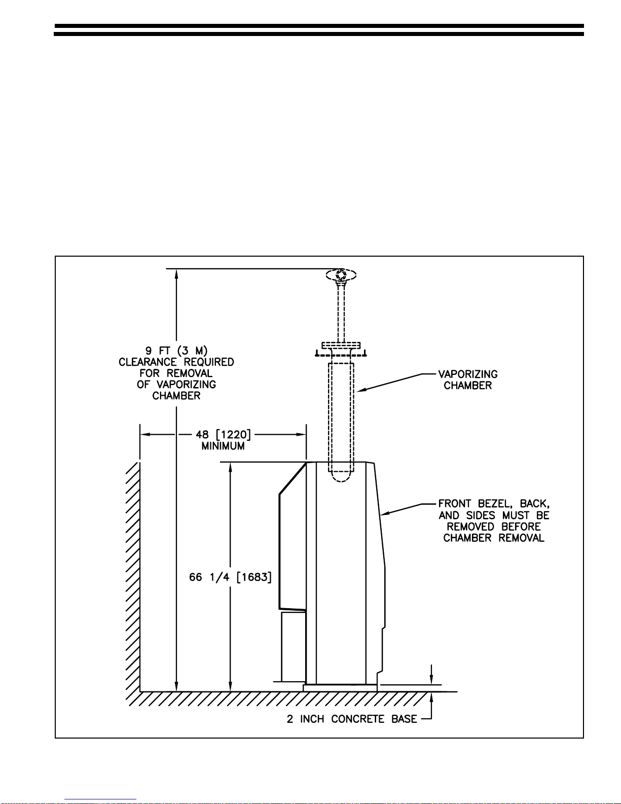
The vaporizer should be located as close to the liquid chemical source as possible. The length of chemical
liquid and gas lines should be kept to a minimum. A vaporizing room should have provisions to exhaust any
leaking gas. A lifting device above the vaporizer is also required. See Figure 5 for dimension requirements.
2.2 Mounting
Install the vaporizer on a mounting pad of concrete or other suitable material approximately 2" (50 mm) high.
Secure using 3/8" diameter bolts. See Figure 4 for mounting hole dimensions.
NOTE: It is recommended that the vaporizer cabinet enclosure be removed from the water tank before
moving the unit from the shipping skid to the mounting pad. This will prevent any damage to the cabinet. On
completion of the vaporizer installation, the enclosure can be reinstalled.
Figure 5 - Cabinet Dimensions and Ultility Locations

115.6001.10 - 12 -
Figure 6 - Vaporizer Piping Connections

- 13 - 115.6001.10
Figure 7 - Typical Manifold Piping
2.3 Piping (See Figures 6 and 7 and Bulletins 115.3002 and 115.3003)
NOTES: All chemical carrying pipes and fittings must be Schedule 80 seamless steel or forged steel
conforming to ASTM A-105 and A-106, Grade B.
All piping, valves and fittings must be thoroughly cleaned of all oils and foreign matter prior to assembly in
accordance with Chlorine Institute Pamphlet #6. Failure to do so may result in a combustible reaction. Steam
is the best method of cleaning, but chlorinated solvents are also acceptable if used in conjunction with the
manufacturer’s safety recommendations.
Prior to assembly, threads on all chemical carrying pipes and fittings should be wrapped with Teflon tape.
Alternately, a mixture of litharge and glycerin may be used on threads. However, if used, the pipe cannot be
taken apart once set.
Connect the chemical gas, liquid lines, and water lines as shown in Figure 6. Plumbing must be in accordance
with local codes. When installing the nipples, tees and 1" ammonia unions into the inlet and outlet ports of the
chemicalvaporizing chamber, be sure the unions are positioned beyond the vaporizer top plate to permit removal
ofthe vaporizer chamber. Make sure thecorrect fittings on the chamber flange are used for the inlet and outlet
pipingorimproperoperationwillresult(SeeFigure4).Theflangeismarkedaccordingly.
2.3.1 Gas Line Connections
a. Install the pressure relief valve as shown in Bulletin 115.6020 and Figure 6. The relief valve must
be installed without a shutoff valve between it and the vaporizer gas outlet. Install a manual
valve in parallel with the pressure relief valve. This valve will normally be in the closed position.
It may be opened as a MANUAL vent valve ONLY. Route a 1" vent pipe from the pressure relief
valve to a point outdoors where gas discharge can be tolerated. Position the end of the pipe
downward so it will not collect foreign matter or water.

115.6001.10 - 14 -
b. Install the pressure reducing valve as shown in Bulletins 115.6010, 115.3002 and Figure 6.
NOTE: The pressure reducing valve must be located as close as possible to the gas discharge of
the vaporizer.
The outlet of the reducing valve should be routed to the process equipment. A 1/4" vent pipe
(Schedule 80 seamless steel or forged steel conforming to ASTM A-105 and A-106, Grade B)
should terminate outdoors in an area that can tolerate gas discharge. DO NOT MANIFOLD
VENT LINES. Position piping so it will not collect foreign matter or water. A screen over the
discharge of the vent line is recommended to prevent clogging.
c. An optional pressure switch set to actuate at 200 psig (1380 kPa/13.8 bar) may be installed in the
gas line between the vaporizer discharge and the pressure relief valve assembly. This will act as
an early warning of an over pressure condition to prevent relief valve venting. See Figure 6.
2.3.2 Liquid Line Connections
a. Installa 1" liquidinletshutoffvalve just prior to the vaporizer inlet ammonia union. An expansion
chamber with rupture disc must be installed upstream of the shutoff valve. (See Figure 6)
Additional expansion chambers must be installed in any lengths of liquid piping if they are
between shutoff valves. All expansion chambers should have a capacity of at least 20% of the
line volume which they protect and should be mounted at the highest point of the liquid line.
Refer to Bulletin 115.6020 for optional configurations.
b. Route 1" pipe from the liquid inlet shutoff valve to the chemical source. (See Figure 7)
c. Install a flexible connector on the 1" pipe. Attach an isolating valve on the free end of the flexible
connector and connect to the liquid valve of the chemical container.
2.3.3 Water Line Connections (See Figure 6)
a. Install1"overflow piping to the outlet provided on the topof the hot water tank. Route to drain. In
order to fit the tank cover on the vaporizer, the overflow pipe must be run straight down the back
of the water bath and exit at the top of the bottom opening on the back cover.
b. Connect 1" unrestricted vent pipe from the tee.
c. Connect 1/2" drain and fill pipe to the outlet provided at the base of the water tank header box.
Install a 1/2" gate valve in the drain line.
d. Install a 1/2" gate valve in line for manual filling. For automatic filling, a 1/2" solenoid valve is
supplied. Keep the manual valve closed at this time.
e. A 10 psig (70 kPa/0.7 bar) minimum potable water inlet must be provided to the filling valve.
f. Install a 4 gpm (15 l/m) flow control valve (noting the direction of flow) in the water fill piping.
2.4 Wiring
CAUTION: Keep electrical power OFF while working on electrical equipment. Do not apply electrical power
directly to the heater circuit without water in the tank as damage will result.
Wire all components per Bulletins 115.3020 or 115.3021. Be sure any connected alarm devices do not
exceed maximum power limitations.
NOTE: All wiring must be in accordance with local codes and regulations. Refer to the NATIONAL
ELECTRICAL CODE (NFPA-70, ARTICLE 500) for special wiring requirements when feeding ammonia.
Refer to Figure 8 for specific locations of terminals and water and heater control components.
2.4.1 Heater Circuit
a. The magnetic contactor, if not cabinet mounted, must be installed on a suitable wall or electric
panel and wired to the heater terminal strip (A-B-C). Refer to the manufacturer’s instruction
manual. A contactor mounted on the vaporizer tank is pre-wired.

- 15 - 115.6001.10
b. Wire the magnetic contactor to a fused safety switch, unless factory installed, and then to the
power source.
2.4.2 Control Circuits
WARNING: Temperature controls are voltage sensitive. Applying improper voltage will destroy the
switch.
a. Wire the control circuit L1 and L2 to a fused safety switch and then to the power source.
b. Wire the electric actuator on the pressure reducing valve or pilot solenoid valve (pneumatic
models only) to the vaporizer terminal strip. See Bulletins 115.3020 or 115.3021.
c. Connect the magnetic contactor coil to the control circuit terminal block.
d. Wire the water fill solenoid valve to the control circuit terminal block. Do not apply power.
2.4.3 Alarm Switches
a. The low water temperature alarm switch can be connected to an outside alarm system. If the
water bath temperature is below a preset limit, the pressure reducing valve will close and the
alarm switch will actuate.
b. The high temperature alarm switch can be connected to an outside alarm system. If the water
bath temperature exceeds a preset limit, power will be cut to the heaters and the alarm switch
will actuate.
c. The low water level alarm switch can be connected to an outside alarm system. If the water bath
level drops below the set point, power will be cut to the heaters and the alarm switch will actuate.

115.6001.10 - 16 -
3 OPERATION
3.1 General
This section covers the operating practices of the Series VAX4600 Vaporizer System, consisting of one
vaporizer, one pressure relief valve, one (optional) pressure reducing valve and one or more liquid line
expansion chambers.
3.2 Pre-startup Components
3.2.1 Vaporizer
Apply power to the vaporizer control circuit to energize the automatic water level control and actuate
the water fill solenoid valve. Open the manual water shutoff valve allowing the water bath tank to fill.
3.2.2 Gas Pressure Relief Valve and Rupture Disc Assembly
The relief valve is calibrated at the factory to open at 250 psig (1700 kPa/17 bar). No additional
adjustment is required. Be sure the manual bypass valve is closed before introducing chemical into
the system. See Bulletins 115.6020 and 115.3004.
3.2.3 Pressure Reducing Valve (Electric and Pneumatic)
See Bulletin 115.6010. Check for operation by actuating the low water temperature alarm switch
(reduce water bath temperature) and observing the valve operation (PRV is opened above the low
water temperature alarm set point and closed below the set point).
3.2.4 Liquid Expansion Chamber Rupture Disc Assembly
See Bulletin 115.3005
3.3 Startup
All persons involved in the operation of the vaporizer equipment should be familiarized with its operation and
any plant emergency procedures. Before continuing with the startup, contact Capital Controls with questions
or to arrange a training program, if necessary.
3.3.1 Start-Up
a. Turn on the power to the heaters (control circuit already on) and allow the water bath
temperature to stabilize. This may take 60-90 minutes.
b. Before introducing chemical into the system. all joints and connections must be checked for
leakage. Make sure that the flexible connector is attached to the gas discharge valve on the
chemical container. Note: It is recommended that, if used, the vacuum ejector be operating as a
precaution to evacuate gas in case of a major leak.
1. Leakage test method with dry air or nitrogen:
aa. Close the manual vent valve (See Figure 6) and pressure test the liquid piping and
vaporizing chamber to 150 psig (1035 kPa/10 bar), with dry air or nitrogen.
Caution: Nitrogen cylinders are pressurized in excess of 2000 psig (13970 kPa/139
bar). Use regulator to assure proper pressure.
Apply soapy water to the outside of the joints to detect leaks. If there are no apparent
leaks, open the manual vent valve to relieve nitrogen pressure and then close.
bb. Open and immediately close the chemical container gas outlet valve, introducing
just enough gas to pressurize the chemical system. Test for leaks by filling a
squeeze bottle 1/4 full of household ammonia. Hold the squeeze bottle near the
suspected points and squeeze the fumes. If gas is leaking, a dense white smoke will
appear.Repair all leaks and retest. Reference Chlorine Institute ChlorineManualand
Pamphlet#6.
- 17 - 115.6001.10
Figure 8 - Chlorine and Sulfur Dioxide Vaporizer Components

115.6001.10 - 18 -
3.3.2 Abnormally High Chemical Supply Pressure
CAUTION: Vaporizer performance will be restricted if ton containers and tank cars produce
abnormally high liquid pressure. Normal ton container pressure ranges (unpadded) are 85-100 psig
(586-690 kPa). Liquid pressure in a padded tank car is normally 125 psig (862 kPa). Vaporizer
capacity is reduced by padding and very low liquid chemical temperature.
Restricted Performance Example
Assume that the liquid chlorine being fed from the tank car is 60°F (15.6°C) and that the vaporizer
water bath temperature is 180°F (82.2°C). The vapor pressure of the liquid chlorine at 60°F (15.6°C)
is approximately 70 psig without any padding, and the thermal difference through the vaporizer
chamber wall between the heated water and the liquid chlorine will be 120°F (49°C). With this
temperature difference, the vaporizer can transfer heat and thereby vaporize the liquid chlorine to
gaseous chlorine.
The Chlorine Institute Pamphlet #54 permits maximum allowable padding pressure to be 190 psig
(1310 kPa) for liquid chlorine at 60°F (15.6°C). In this case, the liquid pressure in the vaporizer tank
then becomes 190 psig (1310 kPa), instead of 70 psig (483 kPa), because of the padding.
From the vapor pressure curve of chlorine, a 190 psig (1310 kPa) vapor pressure is equivalent to
120°F (49°C) so that the vaporizer must heat the liquid chlorine to 120°F (49°C) prior to vaporization.
With the vaporizer water bath at 180°F (82.2°C), a 60°F (15.6°C) change in temperature is available
to vaporize the chlorine instead of a change in temperature of 120°F (49°C) without padding. The
increased heat required to raise the liquid chlorine temperature 120°F (49°C) reduces the vaporizer
capacity and superheat.
To reduce abnormally high liquid chlorine pressure induced by heat (ton containers) or induced by
padding pressure (tank cars), operate on the gas phase of the source (top container valve) until the
pressure drops to approximately 70 psig (483 kPa). The chlorinator can operate to its maximum
capacity at 20 psig (138 kPa) gas pressure at the inlet to the vacuum regulator but 40 psig (276 kPa)
is preferred. Padding of a tank car will only be required when the liquid chlorine temperature is below
30°F (-1.1°C), and then only a small amount of padding is required.
If padding is used and pressure is maintained above 80 psig (552 kPa), chlorine liquid carry-over can
occur, and must be prevented for proper performance.
3.3.3 Shutdown
The vaporizer can be shut down using two methods:
Caution: Liquid chemical must not remain trapped in the vaporizing chamber when the liquid inlet
shutoff valve and gas discharge valve or process equipment is shut off. If liquid is trapped in the
heated vaporizer, the pressure will rise, causing the rupture disc to burst and the pressure relief valve
to open.
a. Method A (preferred)
Shut off the container liquid supply inlet valve at the vaporizer while maintaining the water bath
temperature. The remaining liquid will vaporize and discharge to the process.
Note: The process equipment must be operating. When the gas pressure gauge indicates the
rapid drop in pressure, all the liquid is vaporized. The manual gas discharge valves and the
process equipment may then be shut off.
b. Method B
Shut off the manual gas discharge valves to the process while maintaining the water bath
temperature. The pressure buildup in the vaporizing chamber will cause the liquid chemical to
return to its source. Shut down the process equipment, then shut off the container liquid supply
valve at the vaporizer.
After completing Method A or B, residual pressurized chemical gas may still be in the vaporizer
chamber. Before disconnecting any pipes, open the manual vent valve to make sure all gas is
vented.

- 19 - 115.6001.10
3.4 Calibration
3.4.1 Cathodic Protection Current Adjustment
The current level required to prevent electrolytic degradation of the tank and chamber is between 25
and 30 milliamps as read on the instrument panel ammeter. This should be read and adjusted weekly
using the potentiometer knob directly below the ammeter. A zero reading at all potentiometer
settings indicates replacement of anodes is required. Refer to Service Section.
3.4.2 Relief Valve Calibration
The relief valve will need recalibration upon disassembly for cleaning following an over-pressure
condition. Refer to Bulletin 115.6020.

115.6001.10 - 20 -
4 SERVICE
4.1 Changing Chemical Supply
4.1.1 Withtheprocess equipment operating, shut off the chemical container liquid outletvalve.
4.1.2 Shutoffthe isolating valve on the flexible connection at the chemicalcontainer.
4.1.3 Disconnecttheflexibleconnectionfromtheempty chemical container liquid outlet valve and reconnect
to a full chemical container. Promptly apply the outlet cap and valve protection hood to the empty
containervalve.
4.1.4 Slowlyopen, then immediately close the liquid outlet valve on the full container.
4.1.5 Check for leaks as described in the Startup Section.
4.1.6 Reopenboth valves if noleaksarefound.
4.2 Cleaning
The vaporizer requires periodic cleaning for safe and efficient operation. The frequency varies with usage
and quality of the chemical used. Clean the unit every six months or less, if loss of capacity or superheat is
experienced.
4.2.1 Chamber Cleaning
RefertoFigures 5 and 9 and proceed as follows:
a. Shutdownthevaporizersystem. Refer to Shutdown Section.
b. Turn off the electrical power to the heater and control circuits.
c. Open the 1" drain valve and drain the water from the water bath tank. Close the valve when the tank
is empty.
d. Openthemanualbypass(vent)valveto make sure the pressure is at zero and leave open.
4. Disconnectthe 1" union in the chemical liquid pipe at the vaporizer after the chemical liquid valve.
f. Pass dry air into the vaporizer through the chemical liquid inlet at the disconnected union to purge
thevaporizing chamber.
g. Disconnect the 1" union at the chemical gas outlet. Plug the open port left at the union to the
dischargepiping.
h. Removethe gas temperature and pressure sensors from their protective wells in the chamber.
I. Removethetwoanodes,seeCathodicProtection Section.
j. Removetwelve 3/4"boltsonthechamber flange.
k. Remove thechamberflange vertically from thevaporizingchamber.The baffles anddippipeare
connectedtotheundersideof this cover.
l. Removethe largeleadgasketinthe chamber groove.
m. Remove the eight bolts around the topplate.
n. Withtheuse of lifting equipment, vertically withdraw the chamber from the water bath tank.
Caution: Lift out the chamber using the two (2) lifting points welded to the chamber.
o. Cleanthe inside of the chamber, chamber flange and internal parts withhot water and steam until
thewash water is clean andfree of odor.
p. Thoroughlydry all parts.
q. Examineboth anodes andreplaceifnecessary. Refer to Service Section.
r. Clean the inside of the water bath tank if needed.
s. Examine the water bath tank, chamber, heaters and other internal parts for corrosion. Remove any
whitebuildup on the heaters to prevent premature failure. Replace parts as required.Referto
ServiceSection.
Table of contents


