SEW-Eurodrive MOVIPRO PZO30A-HSIR-S02-B1 Operating instructions

*27792757_0922*
Drive Technology \ Drive Automation \ System Integration \ Services
Addendum to the Operating
Instructions
MOVIPRO® Accessories
HSIR Interface Adapter PZO30A-HSIR-S02-B1
Edition 09/2022 27792757/EN

SEW-EURODRIVE—Driving the world

Table of contents
Addendum to the Operating Instructions – HSIR Interface Adapter PZO30A-HSIR-S02-B1 3
Table of contents
1 General information.................................................................................................................. 4
1.1 About this documentation ...............................................................................................4
1.2 Other applicable documentation .....................................................................................4
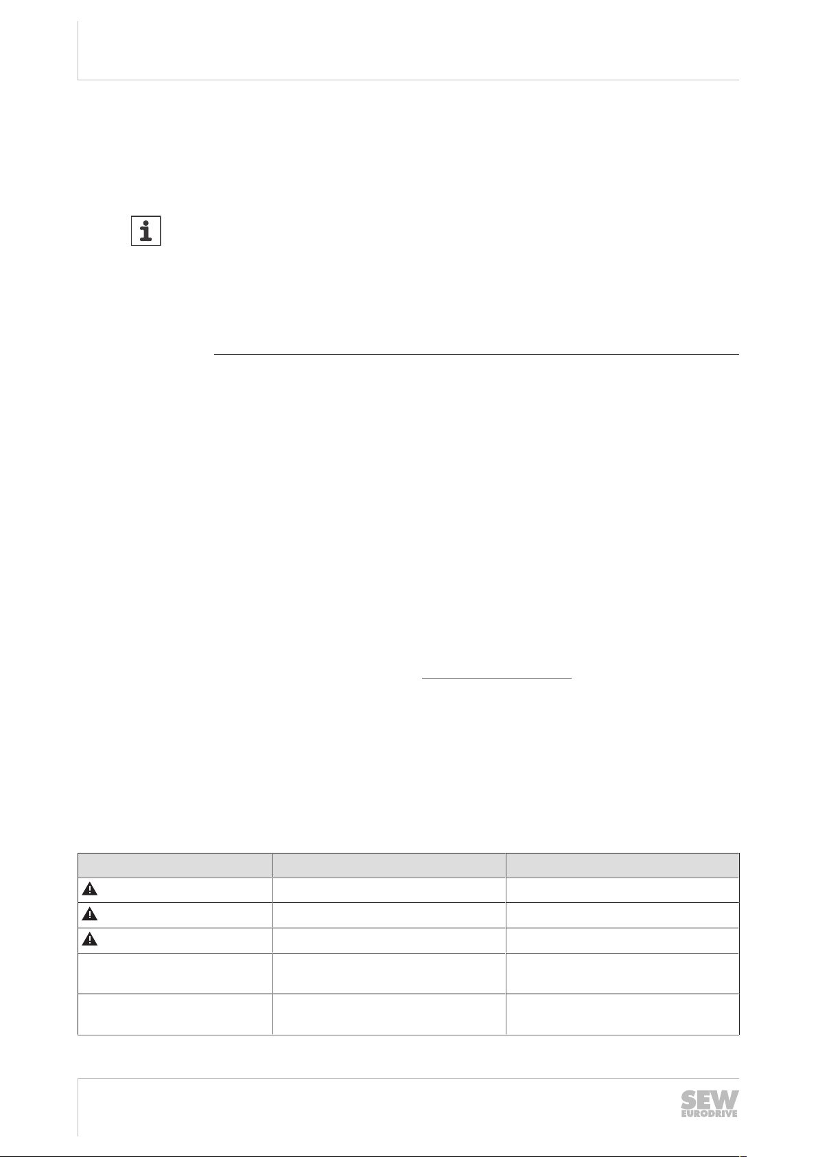
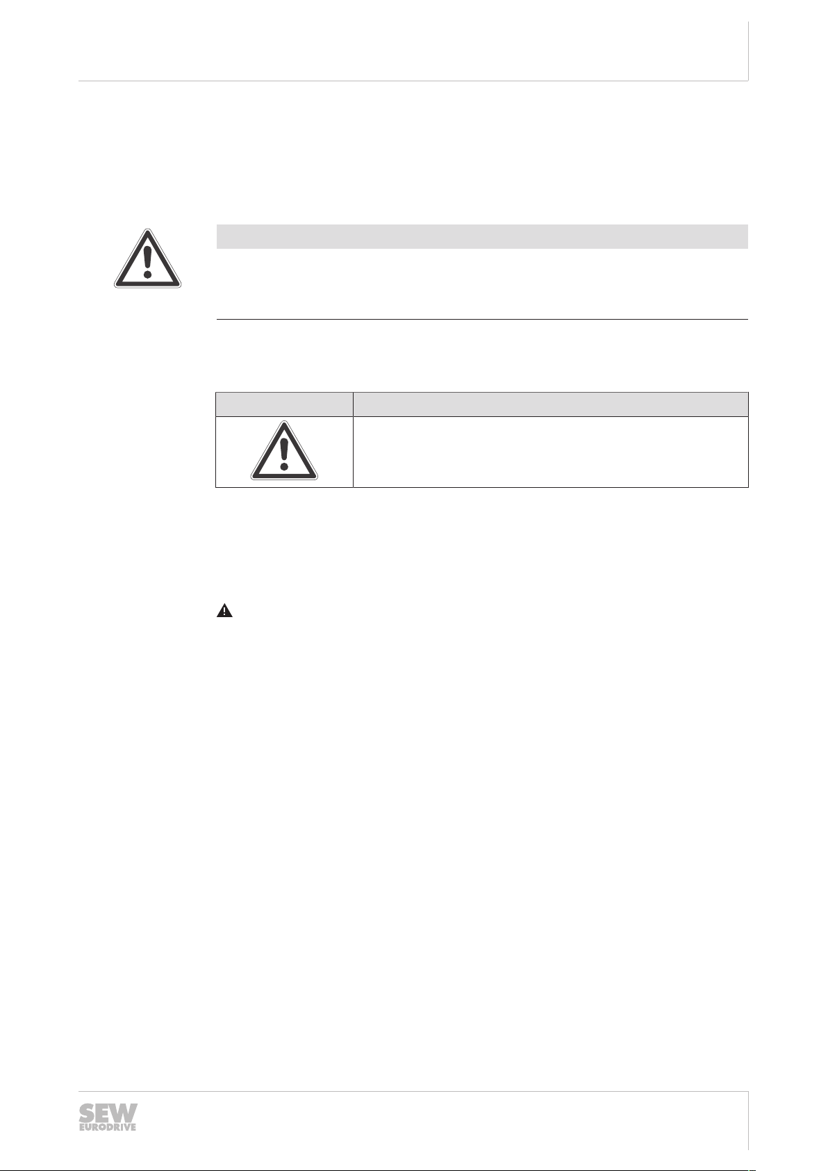
1.3 Structure of the safety notes ...........................................................................................4
1.4 Rights to claim under limited warranty ............................................................................5
1.5 Product names and trademarks......................................................................................5
1.6 Copyright notice ..............................................................................................................5
2 Device structure ....................................................................................................................... 6
2.1 Type designation.............................................................................................................6
2.2 Scope of delivery ............................................................................................................6
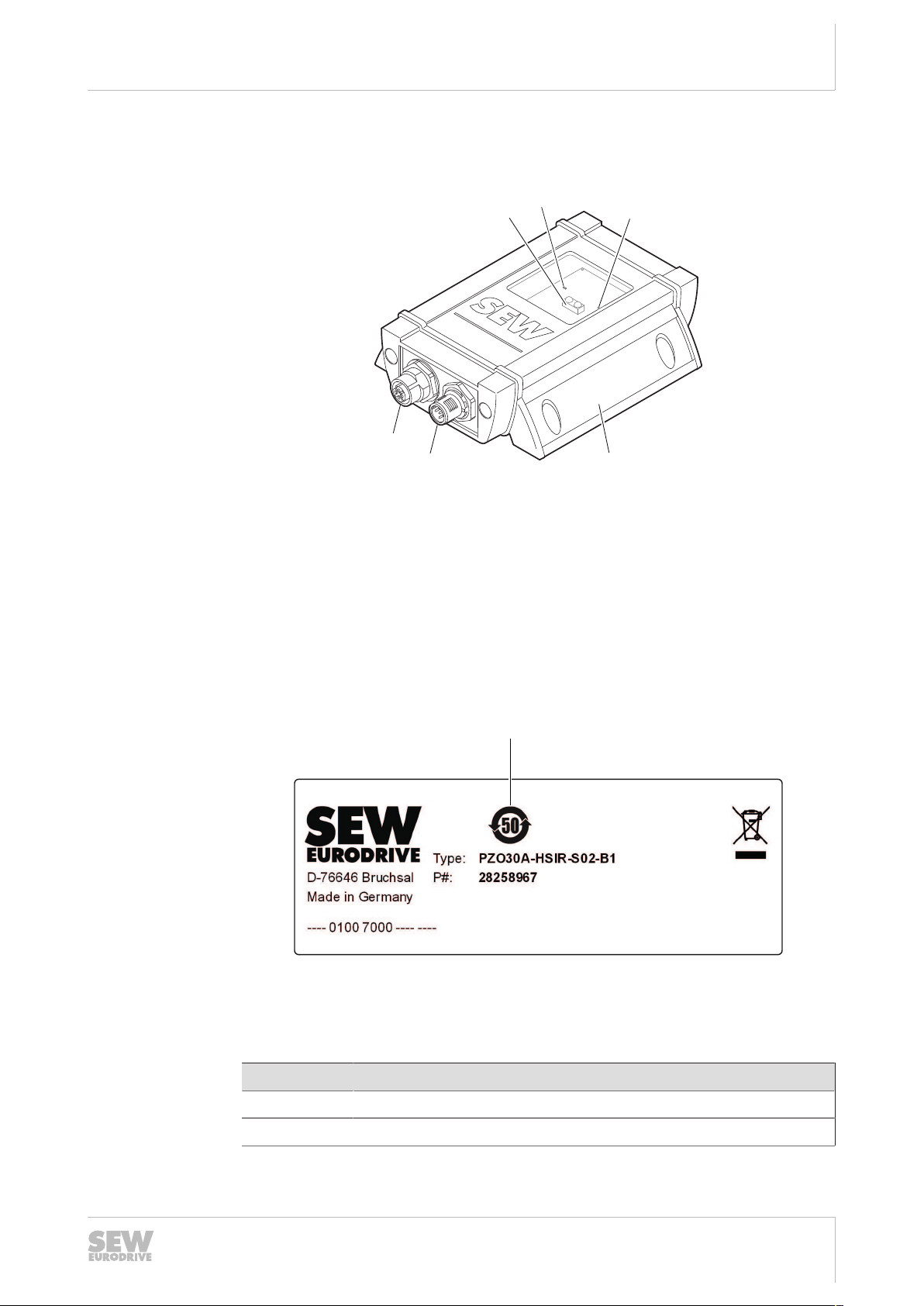
2.3 Basic device....................................................................................................................7
2.4 Nameplate.......................................................................................................................7
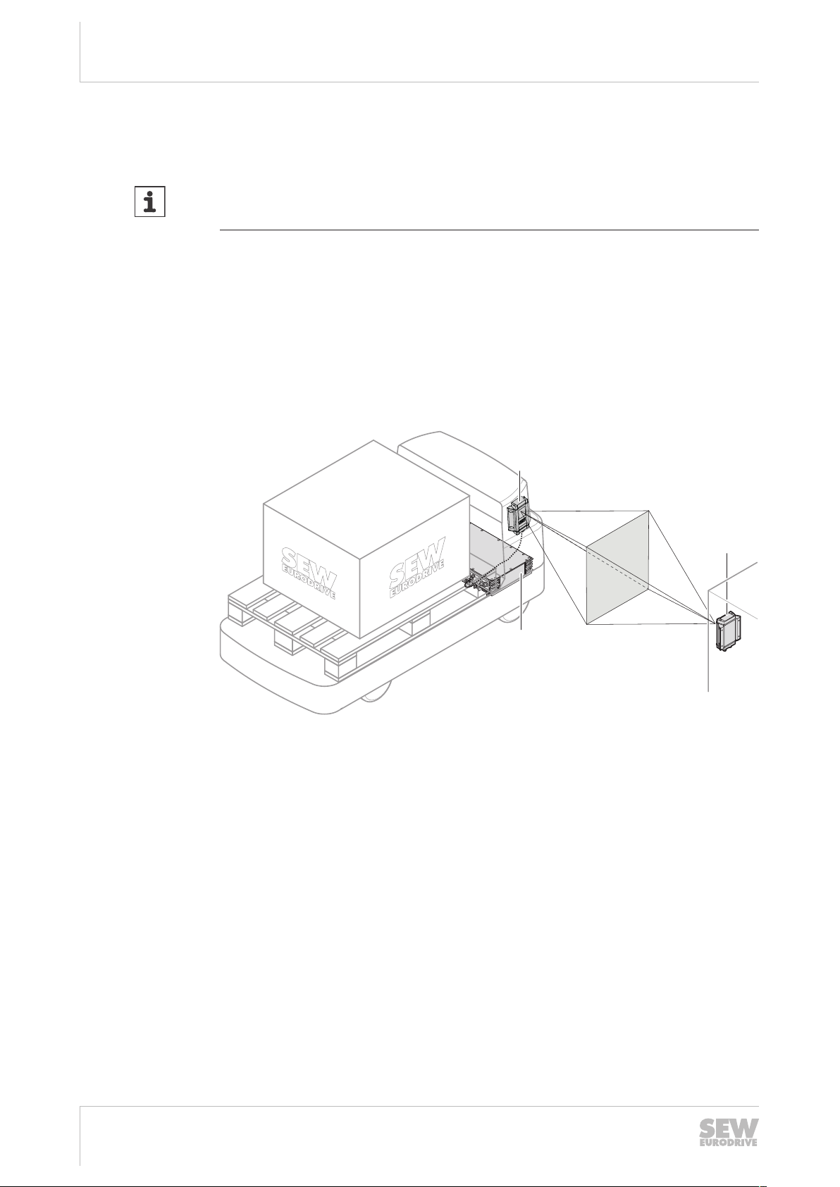
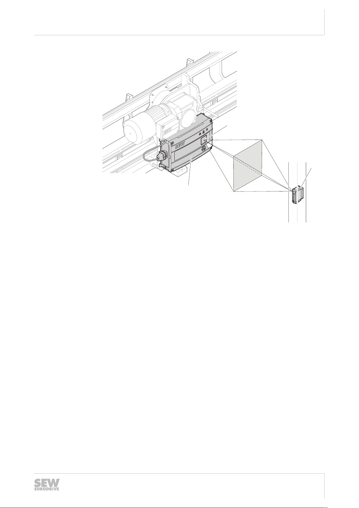
2.5 Functional principle .........................................................................................................8
3 Mechanical installation .......................................................................................................... 10
3.1 Minimum clearance.......................................................................................................10
3.2 Minimum and maximum clearances .............................................................................10
3.3 Procedure .....................................................................................................................10
4 Electrical installation.............................................................................................................. 12
4.1 Shielding .......................................................................................................................12
4.2 X4001: RS485 interface – system bus..........................................................................12
4.3 X4002: RS485 interface – system bus..........................................................................13
5 Operation................................................................................................................................. 14
5.1 Status LED....................................................................................................................14
6 Service..................................................................................................................................... 15
6.1 Maintenance .................................................................................................................15
6.2 Waste disposal..............................................................................................................15
7 Technical data......................................................................................................................... 16
7.1 General .........................................................................................................................16
7.2 Transmission and reception area..................................................................................17
7.3 Dimension drawing .......................................................................................................18
27792757/EN – 09/2022

1General information
About this documentation
Addendum to the Operating Instructions – HSIR Interface Adapter PZO30A-HSIR-S02-B1
4
1 General information
1.1 About this documentation
INFORMATION
The device is designed for use in industrial and commercial systems and machines in
combination with a MOVIPRO® drive and application controller.
The functions of the device depend on the characteristics of the MOVIPRO® drive
and application controller with which the device is operated.
In addition to this documentation, observe the operating instructions as well as all
other applicable documentation of the respective MOVIPRO® drive and application
controller.
The current version of the documentation is the original.
This documentation is an integral part of the product. The documentation is intended
for all employees who perform assembly, installation, startup and service work on the
product.
Make sure this documentation is accessible and legible. Ensure that persons respon-
sible for the systems and their operation as well as persons who work on the product
independently have read through the documentation carefully and understood it. If you
are unclear about any of the information in this documentation, or if you require further
information, contact SEW‑EURODRIVE.
1.2 Other applicable documentation
This documentation supplements the operating instructions of the associated product.
Use this document only in connection with the operating instructions.
Always use the latest edition of the documentation and the software.
The SEW‑EURODRIVE website (www.sew‑eurodrive.com) provides a wide selection
of documents for download in various languages. If required, you can also order print-
ed and bound copies of the documentation from SEW‑EURODRIVE.
1.3 Structure of the safety notes
1.3.1 Meaning of signal words
The following table shows the grading and meaning of the signal words for safety
notes:
Signal word Meaning Consequences if disregarded
DANGER Imminent hazard Severe or fatal injuries
WARNING Possible dangerous situation Severe or fatal injuries
CAUTION Possible dangerous situation Minor injuries
NOTICE Possible damage to property Damage to the product or its envi-
ronment
INFORMATION Useful information or tip: Simplifies
handling of the product.
27792757/EN – 09/2022

1
General information
Rights to claim under limited warranty
Addendum to the Operating Instructions – HSIR Interface Adapter PZO30A-HSIR-S02-B1 5
1.3.2 Structure of section-related safety notes
Section-related safety notes do not apply to a specific action but to several actions
pertaining to one subject. The hazard symbols used either indicate a general hazard
or a specific hazard.
This is the formal structure of a safety note for a specific section:
SIGNAL WORD
Type and source of hazard.
Possible consequence(s) if disregarded.
• Measure(s) to prevent the hazard.
Meaning of the hazard symbols
The hazard symbols in the safety notes have the following meaning:
Hazard symbol Meaning
General hazard
1.3.3 Structure of embedded safety notes
Embedded safety notes are directly integrated into the instructions just before the de-
scription of the dangerous action.
This is the formal structure of an embedded safety note:
SIGNAL WORD! Type and source of hazard. Possible consequence(s) if disre-
garded. Measure(s) to prevent the hazard.
1.4 Rights to claim under limited warranty
Read the information in this documentation. This is essential for fault-free operation
and fulfillment of any rights to claim under limited warranty. Read the documentation
before you start working with the product.
1.5 Product names and trademarks
The brands and product names in this documentation are trademarks or registered
trademarks of their respective titleholders.
1.6 Copyright notice
©2022SEW‑EURODRIVE. All rights reserved. Unauthorized reproduction, modifica-
tion, distribution or any other use of the whole or any part of this documentation is
strictly prohibited.
27792757/EN – 09/2022

2Device structure
Type designation
Addendum to the Operating Instructions – HSIR Interface Adapter PZO30A-HSIR-S02-B1
6
2 Device structure
2.1 Type designation
The type designation of the device contains the following data:
PZO Drive and positioning controlMOVIPRO® accessories
30 Housing: with high degree of protection for mounting to the machine
A1.Generation
–
HSIR Function type: High-speed infrared interface adapter
–
SControl voltage: 24V
02 Communication 2×RS485
–
B1 Baud rate 115.2k
2.2 Scope of delivery
The scope of delivery includes the following components:
Component Part number
HSIR Interface Adapter PZO30A-HSIR-S02-B1 28258967
Protective covers for all plug connectors –
27792757/EN – 09/2022

2
Device structure
Basic device
Addendum to the Operating Instructions – HSIR Interface Adapter PZO30A-HSIR-S02-B1 7
2.3 Basic device
The following figure shows the design of the device:
X4001 X4002
[2]
[1]
[4]
12
3
4
[6]
[5]
[3]
28377867915
[1] Infrared interface [4] Mounting lugs
[2] HSIR TX status LED [5] X4002:
RS485 interface–system bus
[3] HSIR RX status LED [6] X4001:
RS485 interface–system bus
2.4 Nameplate
The nameplate lists information about the device type. The following figure shows an
example of a main nameplate:
[1]
27021626649698955
[1] China RoHS-2 marking
Depending on the device design, the following information is listed on the main name-
plate:
Value Specification
Type Type designation
P# Part number (for customer-specific devices)
27792757/EN – 09/2022

2Device structure
Functional principle
Addendum to the Operating Instructions – HSIR Interface Adapter PZO30A-HSIR-S02-B1
8
2.5 Functional principle
INFORMATION
The device is equipped with a high-speed infrared interface that transmits data via in-
visible laser radiation in laser class1.
The device is an interface adapter and provides 2 communication interfaces for bid-
irectional data transmission. The device can be used as stationary and mobile unit.
The device comes equipped with a high-speed infrared (in brief HSIR) interface. The
HSIR interface is located behind the red inspection window of the device and uses in-
frared light pulses for data transmission.
The wired interface is an RS485 interface. This interface also provides for the 24 V
supply of the device. The RS485 interface is located on the lower housing cover.
There must be a direct line of sight between the device and a receiver for communica-
tion via the HSIR interface. The amount of data that can be transmitted depends on
the travel speed of the mobile HSIR unit and the distance between the two units.
[2]
[3]
[1]
9007227537671051
[1] HSIR interface adapter with infrared interface on the vehicle
[2] HSIR interface adapter with stationary infrared interface
[3] MOVIPRO®
27792757/EN – 09/2022

2
Device structure
Functional principle
Addendum to the Operating Instructions – HSIR Interface Adapter PZO30A-HSIR-S02-B1 9
[1]
[2]
[3]
9007227537674635
[1] MOVIPRO® infrared interface
[2] HSIR interface adapter with stationary infrared interface
[3] MOVIPRO®
27792757/EN – 09/2022

3Mechanical installation
Minimum clearance
Addendum to the Operating Instructions – HSIR Interface Adapter PZO30A-HSIR-S02-B1
10
3 Mechanical installation
3.1 Minimum clearance
During installation, observe the required minimum clearances for connecting cables
and plug connectors.
3.2 Minimum and maximum clearances
Data can be transferred if the HSIR interface adapter is located in the optical reception
area.
• Minimum distance of units: 0m
• Maximum distance of units: 1m
3.3 Procedure
INFORMATION
To ensure proper communication of the HSIR interface, mount the device in such a
way that the inspection window is protected from direct infrared radiation (such as
sunlight and artificial light).
1. Mount the device in such a way that the status display is always clearly visible. For
bore dimensions, refer to the dimension drawings in chapter "Technical
data"(→216).
2. Drill the holes in the appropriate places.
27792757/EN – 09/2022

3
Mechanical installation
Procedure
Addendum to the Operating Instructions – HSIR Interface Adapter PZO30A-HSIR-S02-B1 11
3. Fasten the HSIR interface adapter with M4 screws of the appropriate length and
washers.
X4001 X4002
28533496459
4. Tighten the screws with a tightening torque of 1.8to2Nm.
27792757/EN – 09/2022

4Electrical installation
Shielding
Addendum to the Operating Instructions – HSIR Interface Adapter PZO30A-HSIR-S02-B1
12
4 Electrical installation
4.1 Shielding
Observe the following when shielding:
• Use shielded power and electronics cables
• Connect the shield and make sure it is grounded over a wide area at both ends.
When using cables with multiple shielding, you also have to ground the inner
shields on both ends over a wide area.
4.2 X4001: RS485 interface – system bus
Function
Internal RS485 interface (system bus)
Connection type
M12, 5-pin, female, B-coded
Pin assignment
43
2
5
1
No. Name Function
1 +24V DC 24 V output
2 RS- RS485 data line (-)
3 GND Reference potential
4 RS+ RS485 data line (+)
5 res. Reserved
27792757/EN – 09/2022

4
Electrical installation
X4002: RS485 interface – system bus
Addendum to the Operating Instructions – HSIR Interface Adapter PZO30A-HSIR-S02-B1 13
4.3 X4002: RS485 interface – system bus
Function
Internal RS485 interface (system bus)
Connection diagram
43
2
5
1
No. Name Function
1 +24V DC 24 V output
2 RS- RS485 data line (-)
3 GND Reference potential
4 RS+ RS485 data line (+)
5 res. Reserved
27792757/EN – 09/2022

5Operation
Status LED
Addendum to the Operating Instructions – HSIR Interface Adapter PZO30A-HSIR-S02-B1
14
5 Operation
5.1 Status LED
The status LED is located in the area of the inspection window of the device and indi-
cates the communication and device states.
5.1.1 HSIR TX status LED
State LED Possible cause Measure
Off • The HSIR interface adapter is
not supplied.
• Check if the master device
provides a 24V voltage sup-
ply at its RS485 output.
• Check the cabling.
• If the error message is dis-
played repeatedly, contact
SEW‑EURODRIVE Service.
Flashes red • Data is sent via the HSIR in-
terface. –
Lights up red • Module is supplied. No data is
sent via the HSIR interface. –
5.1.2 HSIR RX status LED
State LED Possible cause Measure
Off • The HSIR interface adapter is
not supplied.
• Check if the master device
provides a 24V voltage sup-
ply at its RS485 output.
• Check the cabling.
• If the error message is dis-
played repeatedly, contact
SEW‑EURODRIVE Service.
Flashes red • Data is received via the HSIR
interface. –
Lights up red • Module is supplied. No data is
received via the HSIR inter-
face.
–
27792757/EN – 09/2022

6
Service
Maintenance
Addendum to the Operating Instructions – HSIR Interface Adapter PZO30A-HSIR-S02-B1 15
6 Service
6.1 Maintenance
The device is maintenance-free. SEW-EURODRIVE does not stipulate any regular
maintenance work. However, it is recommended that you regularly check the following
parts:
• Connection cables:
Damaged or fatigued cables must be replaced immediately.
• Inspection window:
Keep the inspection window clean. If the inspection window is dirty, clean it with a
soft cloth and a mild detergent.
6.2 Waste disposal
Dispose of the product and all parts separately in accordance with their material struc-
ture and the national regulations. Put the product through a recycling process or con-
tact a specialist waste disposal company. If possible, divide the product into the follow-
ing categories:
• Iron, steel or cast iron
• Stainless steel
• Magnets
• Aluminum
• Copper
• Electronic parts
• Plastics
The following materials are hazardous to health and the environment. These materials
must be collected and disposed of separately.
• Oil and grease
Collect used oil and grease separately according to type. Ensure that the used oil
is not mixed with solvent. Dispose of used oil and grease correctly.
• Screens
• Capacitors
Waste disposal according to WEEE Directive2012/19/EU
This product and its accessories may fall within the scope of the country-specific appli-
cation of the WEEE Directive. Dispose of the product and its accessories according to
the national regulations of your country.
For further information, contact the responsible SEW‑EURODRIVE branch or an au-
thorized partner of SEW‑EURODRIVE.
27792757/EN – 09/2022

7Technical data
General
Addendum to the Operating Instructions – HSIR Interface Adapter PZO30A-HSIR-S02-B1
16
7 Technical data
7.1 General
Basic device
Ambient temperature ϑamb -25to+60°C
(non-condensing, no condensation)
Climate class EN 60721-3-3, class 3K3
Storage temperatureϑL-25to+85°C
(EN60721-3-3, class 3K3)
Degree of protection IP55
Mass 0.5kg
Dimensions W×H×D 106.6×131×37.1mm
HSIR interface
General Infrared light pulses
Baud rate 115.2kBaud, 8data bits, 1stop bit, no parity bit
RS485 interface–system bus
General I/O standard
Baud rate 115.2kBaud, 8data bits, 1stop bit, no parity bit
Input voltage range DC 18to30V
Nominal input current 10mADC at U=DC24V
Connection technology 1×M12, 5-pin, female, B-coded
1×M12, 5-pin, male, B‑coded
27792757/EN – 09/2022

7
Technical data
Transmission and reception area
Addendum to the Operating Instructions – HSIR Interface Adapter PZO30A-HSIR-S02-B1 17
7.2 Transmission and reception area
The following diagram shows the width of the transmission/reception area depending
on the distance from the device:
0
5
10
15
20
25
30
35
40
45
50
55
60
65
70
75
80
85
90
95
100
105
110
-40 -35 -30 -25 -20 -15 -10 -5 0 5 10 15 20 25 30 35 40
Vertical distance to the infrared interface in cm
Horizontal/vertical distance to the infrared interface in cm
9007237766288011
27792757/EN – 09/2022

7Technical data
Dimension drawing
Addendum to the Operating Instructions – HSIR Interface Adapter PZO30A-HSIR-S02-B1
18
7.3 Dimension drawing
X4001 X4002
63.8 42 24.8
13.5
12
3
4
1
2
3
4
Ø 8.5
Ø 4.5
106.6
90.2
73.4
>70 130.6
18
37.1
13.5
28377871499
27792757/EN – 09/2022


SEW-EURODRIVE—Driving the world
SEW-EURODRIVE GmbH & Co KG
Ernst-Blickle-Str. 42
76646 BRUCHSAL
GERMANY
Tel. +49 7251 75-0
Fax +49 7251 75-1970
www.sew-eurodrive.com
Table of contents
Other SEW-Eurodrive Adapter manuals