Sfere SC2-A470M1 User manual

LoRa Communication Gateway
User Manual
Applied to:
SC2-A470M1
SC2-A868M1
SC2-A915M1
SC2-B470M1
SC2-B868M1
SC2-B915M1
SC2-A470M2
SC2-B470M2

Thank you for selecting products of JIANGSU SFERE ELECTRIC CO., LTD. For your
convenience of purchasing and safely, correctly and efficiently use of this product,
please read this user manual carefully and pay attention to following points when
using this product.
CAUTION:
The device must be installed and maintained by professionals;
The input signal and power supply must be cut off before any internal or
external operation of the device,
A suitable voltage detection device must be always used to confirm that
there is no voltage at all parts of the meter;
The electrical parameters provided to the device must be within the rated
range
The following conditions will cause damage to the device or abnormal operation
of the device:
The voltage of auxiliary power supply is out of range;
The frequency of auxiliary power supply is out of range;
◆The polarity of current or voltage input is incorrect;
The communication plug is removed with the power on;
The terminals are not connected as required.
Please don’t touch the terminals
when the meter is in operation!
The latest version of this manual can be downloaded on our company's homepage,
and some corresponding test software downloads are also provided. If you need
the electronic version of the user manual, please contact our technical service
department.

Content
1. Version information ..............................................................................1
2. Quick start ............................................................................................. 1
3. Product overview ..................................................................................4
3.1 Naming description .................................................................... 4
3.2 Product parameters ....................................................................5
3.3 Interface description .................................................................. 6
3.4 Working indicator ....................................................................... 6
3.5 Dimensions ................................................................................. 7
4. Application Cases ..................................................................................7
4.1 Features of LoRa Solution .......................................................... 7
4.2 Modbus data acquisition ........................................................... 7
5. Product function ................................................................................... 9
5.1 Working mode selection ............................................................ 9
5.2 Parameter configuration ............................................................ 9
5.3 Signal strength indicator .......................................................... 11
5.4 Firmware upgrade .................................................................... 11

1
1. Version information
Version
number
Author
Date
Description
V1.0.0
Ma Longwei
2021.04.23
April 23rd,
2021
Initial version
V1.0.1
Lu
Xiaocheng
2021.05.07
May 7th, 2021
Modify the RS485 baud rate support
range
2. Quick start
SC2, hereinafter referred to as LoRa communication gateway, can realize the
communication between serial port and LoRa. This chapter mainly introduces the
transparent transmission test guidance of the product.
The related software involved is as follows:
SmartHMI :Sfere general-purpose small gateway configuration tool, which
integrates configuration, debugging, and monitoring, is simple and easy to use.
If you have purchased SC2, there will be the following accessories:
Three conditions must be met for the sender and receiver of data transparent
communication:
Same frequency band
Same frequency
Same rate
This example uses the following parameters for configuration:

2
Parameter
LoRa Communication
Gateway A
LoRa Communication
Gateway B
Frequency band
470
470
Frequency
480M
480M
Rate
5.5K
5.5K
(1) Use the USB to 485 tool to connect the LoRa communication gateway A and B
to the serial device (replaced by a PC), install the antenna on the LoRa
communication gateway, and then power on.
(2) Open the SmartHMI software, select the model of DTU--->SC2, and click
Login.
(3) As shown in the figure, click to open the serial port in turn (select the serial

3
port number corresponding to A and B, serial port parameters: 9600, N.8.1),
enter the configuration mode, read the parameters, configure the parameters
in the above table, and update the configuration. After the configuration is
updated successfully, click OK in the pop-up dialog box.
(4) In the SmartHMI debugging information column, LoRa communication
gateway A sends data, and LoRa communication gateway B can receive data.

4
3. Product overview
The LoRa communication gateway uses a serial port for data transmission and
reception, which reduces the threshold for wireless applications and can realize
one-to-one or one-to-many communication.
3.1 Naming description
SC2 -A470 M1
Transmit power:
M1: 100mW
M2: 1W
Frequency band:
470: 470M~510M
868: 848M~888M
915: 895M~935M
Operating voltage:
A:AC/DC 80~270V
B:DC 20~36V

5
3.2 Product parameters
Model
SC2-A470M1
SC2-A868M1
SC2-A915M1
SC2-B470M1
SC2-B868M1
SC2-B915M1
SC2-A470M2
SC2-B470M2
LoRa interface
Working frequency
band
470:470M~510M
868:848M~888M
915:895M~935M
Transmit power
M1:Max. 100mW, M2: Max. 1W
Receiving sensitivity
Hardware parameters
RS485 interface
Baud rate: 1200bps~9600bps
Data format: N.8.1, O.8.1, N.8.2, E.8.1
Operating voltage
AC/DC 80~270V or DC 20~36V
Operating
temperature
-25°C -- 70°C
Storage temperature
-40°C -- 85°C
Relative humidity
≤95%RH, no condensation
Working altitude
≤2000m
Anti-pollution grade
No corrosive gas
Protection level
IP20
Insulation
Signal, power, output terminal to case resistance>100MΩ
Withstand voltage
Input and power supply 2kV, input and output 2kV,
power supply and output 2kV

6
3.3 Interface description
Antenna interface
SMA antenna base (outer screw and inner hole).
RS485 interface
RS485 interface: RS485 has two leads, A and B respectively. When connecting to
the device, A is connected to A, and B is connected to B.
Reset button
Reset button: This button is for restoring factory settings. When the device is in
normal working status, press this button and hold until all the indicators are off and
then release it to restore the device's setting parameters to the factory
configuration status (serial port parameters: 9600, N.8.1).
3.4 Working indicator
Indicator
light
Features
Description
Power Indicator
Always on when the
power input is correct
Communication indicator
Flashing during LoRa data
transmission

7
3.5 Dimensions
4. Application Cases
4.1 Features of LoRa Solution
1. The LoRa communication gateway is a half-duplex communication method
(similar to wired 485). Only one device can send data in the same channel at the
same time, and it does not support multiple slave devices to send data to the host
device at the same time.
2. The LoRa communication method takes a long time in the air and is not suitable
for scenarios with high real-time requirements.
3. The lower the LoRa rate, the longer the transmission distance, the stronger the
anti-interference ability, and the longer it takes to send data.
4.2 Modbus data acquisition
Applicable scenarios: data collection for power meters, water meters, etc.
Applicable mode: transparent transmission mode
Matching products: can be matched with smart wireless power meters
Application details:

8
The meter reading software issues Modbus query commands to the LoRa
communication gateway (master station), and the LoRa communication gateway
(master station) wirelessly transmits the Modbus query commands to the LoRa
communication gateway (slave station) or smart wireless power meter (slave
station) through LoRa, The Modbus device under the slave station selects to report
data according to the query instruction, and complete a data collection via the
following process:
Slave → Master → Meter reading software
Speed setting:
1. When there is less penetration of solid walls, you can try to select the rate of
3.1K and 5.5K; When there is more penetration of solid walls, you can try to use
the rate of 0.3K for testing. Obstacles will shorten the communication distance,
which is subject to the actual test.
2. This data acquisition scheme is also suitable for DL/T 645 and other similar
Modbus protocol acquisition methods.
3. In order to avoid signal interference, the data of only one slave device can be
collected at the same time, and multiple slave devices are not supported to report
data at the same time.
4. The 485 bus of this LoRa communication gateway supports up to 32 Modbus
devices.
5. The rate level of LoRa has a great influence on the transmission time, so you
should pay attention to the setting of Modbus receiving timeout

9
5. Product function
5.1 Working mode selection
Operating mode
Introduction to Mode
Configuration mode
It is used to query and set the parameters of the LoRa
communication gateway.
Transparent
transmission mode
It can realize one-to-one or one-to-many data
transparent transmission, playing the role of serial port
wireless extension.
5.2 Parameter configuration
(1) Enter configuration mode, click to read configuration.
(2) Configure RS485 parameters.
Parameter
Description
Baud rate
1200bps~9600bps
Data Format
N.8.1, E.8.1, O.8.1, N.8.2
(3) Configure LoRa parameters.
LoRa has two configuration modes: Default and custom.

10
Default configuration mode: It is necessary to ensure that the frequency band,
frequency, and rate of each communication gateway are consistent.
Custom mode: It is necessary to ensure that the frequency, spread spectrum,
bandwidth, and coding rate of each communication gateway is consistent.
Mode
Parameter
Default
Frequency band
Frequency
Rate
Transmit power
Custom
Frequency
Transmit power
Spread spectrum
Bandwidth
Code rate
(4) Click to update configuration.
(5) A prompt box will pop up when the configuration is updated successfully,
click OK.

11
5.3 Signal strength indicator
This function can check the signal strength of both parties in communication,
which can provide a reference for evaluating the communication quality of the
LoRa communication gateway.
(1) First, set the frequency band, frequency and rate of LoRa communication
gateway A and LoRa communication gateway B to ensure that both parties can
communicate.
(2) The LoRa communication gateway A enters the configuration mode.
(3) LoRa Communication Gateway B uses serial port tool to send data
periodically.
Click Read Parameters on SmartHMI to view the signal strength (the larger the
value is, the more stable it is).
Note: It is recommended to use the signal strength within the range of -120~0.
5.4 Firmware upgrade
(1) Click Firmware upgrade under Gateway in the menu bar of the SmartHMI
software tool.
(2) IAP Tool host computer pop up. Set the parameters of serial port (select the

12
port number as well as the baud rate, data bit, stop bit and parity check bit of
the APP program) and open the serial port.
(3) Click the Send File button, select Sfere as the protocol, and click to enter IAP;
The entry is successful, and the power indicator flashes quickly.
Note: After entering IAP, the communication parameters must be configured as
9600, N.8.1, and the firmware program can be downloaded normally.
(4) Click the Open button to add the BIN file which is to be downloaded, and then
click the Send button.

13
(5) When the Send Complete prompt box pops up, click the OK button; If you
select to enter the APP after completion, you can close the prompt box and
enter the application to execute;
F10505540004-20IH0 V1.0.1
Technical specifications are subject to change without prior notice.
This manual suits for next models
7
Table of contents
Popular Gateway manuals by other brands
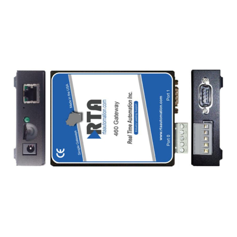
RTA
RTA 460PSBMS-N34 Product user guide
Rohde & Schwarz
Rohde & Schwarz R&S GW5420 installation manual
ZyXEL Communications
ZyXEL Communications ZYWALL - CLI reference guide

enphase
enphase Envoy-S Getting started guide
ATC Technology
ATC Technology ATC-3002 quick start guide

WEG
WEG X1000 Quick installation guide
