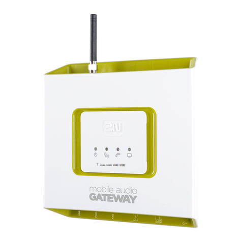
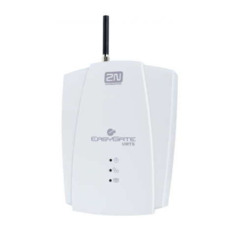
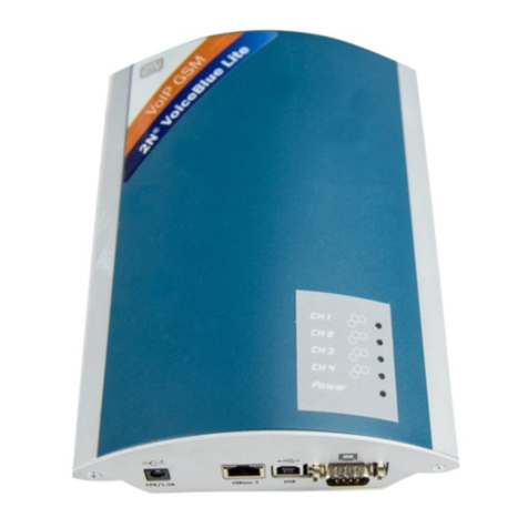
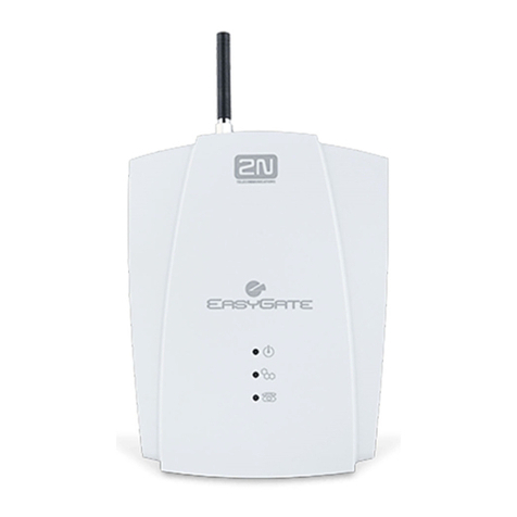
2N SmartGate User manual

2N
SmartGate
GSM gateway
User guide
Version 1.1.2 www.2n.cz

The 2N TELEKOMUNIKACE a.s. joint-stock company is a Czech manufacturer and supplier
of telecommunications equipment.
The product family developed by 2N TELEKOMUNIKACE a.s. includes GSM gateways,
private branch exchanges (PBX), and door and lift communicators. 2N TELEKOMUNIKACE
a.s. has been ranked among the Czech top companies for years and represented a
symbol of stability and prosperity on the telecommunications market for almost two
decades. At present, we export our products into over 120 countries worldwide and have
exclusive distributors on all continents.
2Nis a registered trademark of 2N TELEKOMUNIKACE a.s.. Any product and/or other
names mentioned herein are registered trademarks and/or trademarks or brands
protected by law.
2N TELEKOMUNIKACE administers the FAQ database to help you quickly find information
and to answer your questions about 2N products and services. On faq.2n.cz you can find
information regarding products adjustment and instructions for optimum use and
Declaration of Conformity
2N TELEKOMUNIKACE a.s. hereby declares that the 2NEasyRoute product complies
with all basic requirements and other relevant provisions of the 1999/5/EC directive. For
the full wording of the Declaration of Conformity see the CD-ROM enclosed and at www.2n.cz.
2N TELEKOMUNIKACE is the holder of the ISO 9001:2000 certificate. All development,
production and distribution processes of the company are managed by this standard and
guarantee a high quality, technical level and professional aspect of all our products.

Table of Contents
1. Product Overview...............................................................7
1.1 Product Description ....................................................................................................... 8
Basic Features.................................................................................................................. 8
Advantages of 2N® SmartGate use ................................................................................. 8
Safety Precautions ........................................................................................................... 9
1.2 Changes ........................................................................................................................ 10
1.3 Terms and Symbols Used ........................................................................................... 11
Manual Symbols ............................................................................................................. 11
Future functions.............................................................................................................. 11
2. Description and Installation ............................................13
2.1 Description.................................................................................................................... 14
Telephone Line Tones –Operational Tones.................................................................. 15
Telephone Line Tones –Programming Mode................................................................ 16
2.2 Before You Start ........................................................................................................... 17
Product Completeness Check........................................................................................ 17
Installation requirements ................................................................................................ 17
2.3 Mounting ....................................................................................................................... 19
External Antenna Connection......................................................................................... 19
SIM Card Installation ...................................................................................................... 19
Wall mounting................................................................................................................. 20
Power Supply Connection .............................................................................................. 20
2.4 Telephone line connection .......................................................................................... 21
DialThru gateway –basic connection ............................................................................ 21
Gateway for extension line of PBX................................................................................. 21
Gateway for trunk line of PBX ........................................................................................ 21
Gateway for both, trunk and extension, lines of PBX..................................................... 21
2.5 SMS Sending Input Connection.................................................................................. 22
3. Configuration 2N® SmartGate ........................................23
3.1 2N® SmartGate parameters configuration.................................................................. 24
PC Connection ............................................................................................................... 24
2N® SmartGate Parameter Programming...................................................................... 24
Telephone Line based Programming ............................................................................. 24
PC based Programming ................................................................................................. 25
Further Data Handling Options....................................................................................... 27
Monitoring....................................................................................................................... 28
Firmware Upgrade.......................................................................................................... 29
3.2 Table of Parameters ..................................................................................................... 30

Telephone interface FXS parameters ............................................................................ 30
Telephone interface FXO parameters............................................................................ 35
FXS routing table parameters ........................................................................................ 39
FXO routing table parameters ........................................................................................ 43
GSM routing table .......................................................................................................... 46
SMS Sending Input Parameters..................................................................................... 48
GSM & SIM Parameters................................................................................................. 49
Service Parameters ........................................................................................................ 52
Initialization..................................................................................................................... 53
Security Parameters ....................................................................................................... 54
4. Function and Use .............................................................55
4.1 Voice function............................................................................................................... 56
DialThru gateway............................................................................................................ 56
Gateway for extension line of PBX................................................................................. 58
Gateway for trunk line of PBX ........................................................................................ 59
Configuration of network services .................................................................................. 59
Call forwarding................................................................................................................ 60
Call waiting ..................................................................................................................... 62
Call hold.......................................................................................................................... 62
4.2 FAX and Data function ................................................................................................. 64
Sending fax message or modem connection to and from PSTN ................................... 64
Sending fax message or modem connection to and from GSM .................................... 64
Supported fax and data protocols .................................................................................. 65
4.3 SMS Sending Input....................................................................................................... 67
4.4 COM –Serial Interface ................................................................................................. 68
Programming, Monitoring ............................................................................................... 68
CSD PC-PC Data Transmission..................................................................................... 69
CSD or High-Speed GPRS Data Connection to Internet ............................................... 69
CSD or GPRS Data Connection?................................................................................... 69
SMS Sending and Receiving.......................................................................................... 70
Combination of COM Traffic with Voice Calls ................................................................ 70
List of Supported AT Commands ................................................................................... 70
4.5 SIM Card PIN protection .............................................................................................. 71
PIN Entering by PCManager .......................................................................................... 71
PIN Entering via Telephone Line.................................................................................... 71
Automatic PIN Entering .................................................................................................. 72
4.6 Free minutes option ..................................................................................................... 73
Basic description ............................................................................................................ 73
Parameters –password access ..................................................................................... 73
Commands –direct access ............................................................................................ 74
Setting of free minutes option - PCManager .................................................................. 75
Using Free minutes option –step by step...................................................................... 76
5. Technical parameters ......................................................77

5.1 Technical Parameters .................................................................................................. 78
GSM ............................................................................................................................... 78
Power Supply ................................................................................................................. 78
Telephone Interface FXS (for PBX external line or phone set) ...................................... 78
Telephone Interface FXO (for PBX extension line) ........................................................ 79
Dial thru parameters ....................................................................................................... 79
SMS Sending Input ........................................................................................................ 79
Data Interface ................................................................................................................. 80
Others............................................................................................................................. 80
6. Supplementary Information ............................................81
6.1 Regulations and directives.......................................................................................... 82
6.2 Troubleshooting ........................................................................................................... 83
6.3 List of Abbreviations.................................................................................................... 85
6.4 General Instructions and Cautions ............................................................................ 87
Electric Waste and Used Battery Pack Handling ........................................................... 88


7
1
1. Product
Overview
In this section, we introduce the 2N® SmartGate product, outline its application
options and highlight the advantages following from its use. This chapter also includes
safety instructions.
Here is what you can find in this section:
Product Description
Manual changes description
Abbreviations, Terms and Pictograms Used.

Product Description
1.1
8
1.1 Product Description
Basic Features
The primary purpose of is to transmit voice between GSM
network and attached phone terminals. You can connect terminal with FXO
interface (trunk line of PBX, phone set, answering machine etc.) to FXS
interface on (connector with phone icon) and terminal with
FXS interface (extension line of PBX) to FXO interface on
(connector with crossed out phone icon).
You can establish data connections (GPRS, CSD) and send/receive SMS using
in combination with a PC and appropriate software.
You can send an SMS to a pre-programmed number using the SMS sending
input.
Analogue fax transmission on some models.
Advantages of 2N® SmartGate use
Call cost cutting the calls are routed to GSM or analog network according
to their number prefix. Route all GSM calls from PBX to to
save a lot on PSTN GSM calls.
Easy installation you can easy program as you need with
enclosed SW.
You get all you need in the delivery your delivery
contains all you need to operate the system (the power supply adapter,
telephone cables, PC serial cable, SMS input connector, CD-ROM with
software).
Solution for sites without telephone lines such as mountain chalets,
exhibitions, conferences, etc.
DialThru technology all your calls will be routed most cost-effective way.
ME –Mobility Extension you newer miss an incoming call from analog
network. Incoming call will ring on connected phone and on your mobile
phone too.
CLIP - is equipped with the FSK-based CLIP feature, so if a
Quick data connection transmits data using the high-
speed GPRS connection (GPRS class 10, max. 85.6 kbps).
SMS sending input simply send an SMS to a pre-programmed number by
closing the contact. Recommended for easy supervision, simple securing, etc.
Radiation hazard minimization you are not exposed to a direct effect of
the antenna RF electromagnetic field while telephoning as opposed to mobile
telephones.
Full GSM coverage - is available as quadband (850, 900,
1800, 1900MHz).

Product Description
1.1
9
Safety Precautions
Do not switch on in the vicinity of medical apparatuses to
avoid interference. The minimum distance of the antenna and pacemakers
should be 0.5m.
Do not switch on SmartGate aboard of a plane.
Do not switch on SmartGate near petrol stations, chemical facilities or
sites where explosives are used.
Any mobile telephone use prohibition based on RF energy radiation applies to
SmartGate too.
SmartGate may disturb the function of TV sets, radio sets and PCs.
Warning! SmartGate contains components that can be swallowed by
small children (SIM card, antenna, etc.).
The voltage value mentioned on the adapter may not be exceeded. If you
connect SmartGate to another power supply, make sure that the voltage
value is in the acceptable range.
When your SmartGate comes to the end of its operational life, dispose of
it in accordance with applicable regulations.

Changes
1.2
10
1.2 Changes
Manual
Version
Amendments to Earlier Versions
1.0.0
The User Manual applies to FW Version 1.00A.
1.0.1
Analogue FAX support. (optionally).
1.0.2
Analogue Modem support, Network directing services support
1.0.3
Quadband version
1.0.4
Programming parameters using phone line (DTMF programming)
1.1.1
New design of manual
1.1.2
New version of PCManager (PCManagerUNI 2.04),
Digital DTMF option
AMR set on/off
Quadband version only
Free minutes option only FW 1.5x and 3.5x
Caution
The manufacturer continuously meets customer requirements by
improving the firmware. For the latest processor
firmware, programming tool and User Manual see www.2n.cz.
For a detailed description of the firmware upgrade refer
to the section devoted to the PC programming tool.

Terms and Symbols Used
1.3
11
1.3 Terms and Symbols Used
Manual Symbols
Safety
Always abide by this information to prevent persons from injury.
Warning
Always abide by this information to prevent damage to the device.
Caution
Important information for system functionality.
Tip
Useful information for quick and efficient functionality.
Note
Routines or advice for efficient use of the device.
Future functions
Grey marked text in this document specifies functions of 2N® SmartGate , which will
be supported in the future.


13
2
2. Description and
Installation
This section describes the2N® SmartGate product and its installation.
Here is what you can find in this section:
Product Description
Before You Start
Mounting
Telephone line connection
SMS Sending Input connection

Description
2.1
14
2.1 Description
consites of GSM gateway in white plastic cover, removable antenna
and cables for connecting to phone set and PC
2NSmartGateindicated by LED diodes on its front side. All possible states
are described in the following figure.
SMS connector
SMS sending input
Telephone line
FXS interface
(RJ 12, 6/2)
Telephone line
FXS interface
(RJ 12, 6/2)
Power supply
connector
(DC Jack 2.1 mm)
RS-232C serial line
(D-Sub 9 pins)
Power supply
Light blue
Power supply is connected and
SmartGate is powered
Flashes 1x in 2 s
HW error, HW error, contact the
manufacturer
No light
Power supply is not connected
GSM network
Light blue
Registered to GSM
Flashes:
1× in 1 s - not registered, SIM card inserted
1× in 3 s - not registered, SIM card not inserted
4× quickly - enter your PIN
8× quickly - enter your PUK
quickly continuously = all functions are blocked.
Phone line programming mode - the LED indicates
signal strength. It flashes repeatedly 1-5 times,
depending on signal strength
Telephone line
No light
Standby
Orange for FXS interface:
Flashes quickly - line off-hook or ringing
Light = call FXS GSM
Flashes once in 3s - data connection in progress
On FAX models
Flashes 2×then pause - fax connection in progress;
after power on signalize need of FW upgrade
Flashes 3×then pause - fax connection in progress
Green for FXO interface:
Flashes quickly - line off-hook or ringing
Light - call FXO GSM
Alternately orange and green:
Quickly - ringing from FXO is connected to
FXS interface
Slowly = call FXS FXO
Figure 2.2
2N®SmartGate
Connectors
Figure 2.1
2N®SmartGate
LED indicators

Description
2.1
15
Telephone Line Tones –Operational Tones
The GSM gateway sends tones to the telephone line to indicate the line status. The
tone frequency is 425 Hz in initial setting. Frequency is programmable; it is possible to
set up double frequency tones.
Dial tone
continuous or morse A
is ready to receive dialing.
Ringing tone
Only
The called subscriber's telephone is ringing.
The GSM network or connected PBX transmits this tone. For connection to
GSM network is possible to generate this tone in Gateway according to
setting. This tone is generated till the GSM network starts to transmit
Ringback tone.
Busy tone
, programmable cadency
In case of call routing to GSM network generate busy tone in any of
the following cases:
The SIM card has not been installed.
is not registered to GSM network.
is registered into a foreign network but roaming is disabled.
The called subscriber line is busy.
The called subscriber hangs up (disconnection).
The called number has too many digits (more than 30).
The called number is barred.
generate busy
tone in any of the following cases:
Line is not connected. There is no current on the line.
The called number has too many digits (more than 30).
The called number is barred.
If the called subscriber line is busy or called subscriber hangs up, busy tone is
generated by PBX.

Description
2.1
16
Dialing end signaling
Only
Dialing reception has been terminated. Connection is being established.
PIN tone
Enter the PIN code.
This tone is transmitted upon power up if the PIN has to be entered manually.
PUK tone
Enter the PUK code.
This tone is transmitted upon repeated wrong PIN entering attempts. SIM card
is blocked.
Telephone Line Tones –Programming Mode
Tones confirming/refusing the values entered are transmitted during telephone line
based programming. Each tone has a different melody.
Confirmation
Confirms that the service password or parameter number entered is correct
and has been accepted.
Refusal
Incorrect parameter number;
Incorrect parameter value
Transmitted when a parameter is cancelled with a .
Saving
Parameter value entered is correct and has been saved

Before You Start
2.2
17
2.2 Before You Start
Product Completeness Check
Check the product for completeness before installation please:
12NSmartGate
Antenna for direct connection1)
Magnetic Antenna with coax cable1)
2
PC-connection serial cable
SMS sending input connector
Screw
-ROM with User Manual and software2)
Installation Guide + mounting pattern
Note
1) The delivery includes an antenna to be connected directly to the
SMA connector. An antenna with a cable should be used
when GSM signal is poor or in case of interference with other devices
2) Enclosed software:
PCManager
SMSgateway for easy SMS sending and receiving
Driver for PC
User Manual in format PDF
Lists of AT Commands for SIEMENS GSM modules used
Installation requirements
is designed for vertical mounting on suspension holes (use the
mounting pattern). This position is the best for signal reception because a
vertical antenna is used. can be operated in the horizontal
position too where the GSM signal is good.
Install with respect to the GSM signal strength check the signal
strength using the PCManager.
Place out of range of sensitive devices and human bodies for
electromagnetic interference reasons.
For the allowed range of operating temperatures refer to
Parameters

Before You Start
2.2
18
can disturb other telecommunication systems. Place phone lines
It is impossible to operate on sites exposed to direct solar
radiation or near heat sources.
is designed for indoor use. It may not be exposed to rain, flowing
water, condensed moisture, fog, etc.
may not be exposed to aggressive gas, acid vapours, solvents,
etc.
is not designed for environments with high vibrations such as
means of transport, machine rooms, etc
Caution
Check that you have everything needed for start-up (SIM
card, analogue phone set or FXO port of PBX, eventually PC etc.)

Mounting
2.3
19
2.3 Mounting
External Antenna Connection
Screw the antenna enclosed into the SMA antenna connector.
Caution
Tighten the antenna connector gently with your hand never use
wrenches!
Note
The antenna enclosed has a sufficient gain for trouble-free operation in
normal conditions. If the GSM signal is poor or you want to place your
antenna separately from SmartGate, you can use an antenna with an
SMA-connector terminated cable. The antenna should be mounted
vertically.
The Antenna shall be located within the same building as the main equipment.
Technical Parameters”.
SIM Card Installation
card and close it
properly.
Cautions
network supported by your version.
Select the required GSM provider and SIM card services, such as call
forwarding, call barring, preferred networks, SMS service centre, etc. in
your mobile phone before inserting your SIM card in 2N®SmartGate.
Figure 2.3
SIM Card
Installation

Mounting
2.3
20
Wall mounting
is equipped with two hangings on the back side for wall mounting. For
drilling holes to the wall could be used drill pattern in QuickStart.
Power Supply Connection
is fed with 10-16V DC. Where a source other than the included power
supply adapter is used, the voltage range and polarity shown on the
power supply connector have to be maintained.
Warning
Do not activate the power supply until the antenna is connected to
to avoid the GSM module damage.
Figure 2.4
Zavěšení
2N®SmartGate
na zeď
Other manuals for SmartGate
2
Table of contents
Other 2N Gateway manuals
Popular Gateway manuals by other brands

ZyXEL Communications
ZyXEL Communications P-661H-D Series Support notes

Wintec
Wintec WB-7823 Connection guide

BAPI
BAPI 50387 Installation & operating instructions

Allied Telesis
Allied Telesis AT-iMG646BD-ON datasheet

ZyXEL Communications
ZyXEL Communications 802.11g HomePlug AV ADSL2+ Gateway... user guide

Sensaphone
Sensaphone WSG30 user manual