GivEnergy GIV-AIO-13.5 User manual

ALL IN ONE + GIV-GATEWAY
INSTALLATION GUIDE
AUS | V1.0 30.10.23
GIV-AIO-13.5 | GIV-AIO-13.5-3.6 | GIV-AIO-13.5-4.6 | GIV-AIO-13.5-5.0
GIV-AIO-GW1

CONTENTS
Installation Requirements
Installation of the GivEnergy All in One and Giv-Gateway must be carried out by a GivEnergy Approved
Installer, in accordance with local wiring regulations, legislation around the installation of energy
storage products, and a CEC approved battery installer.
Unit Information
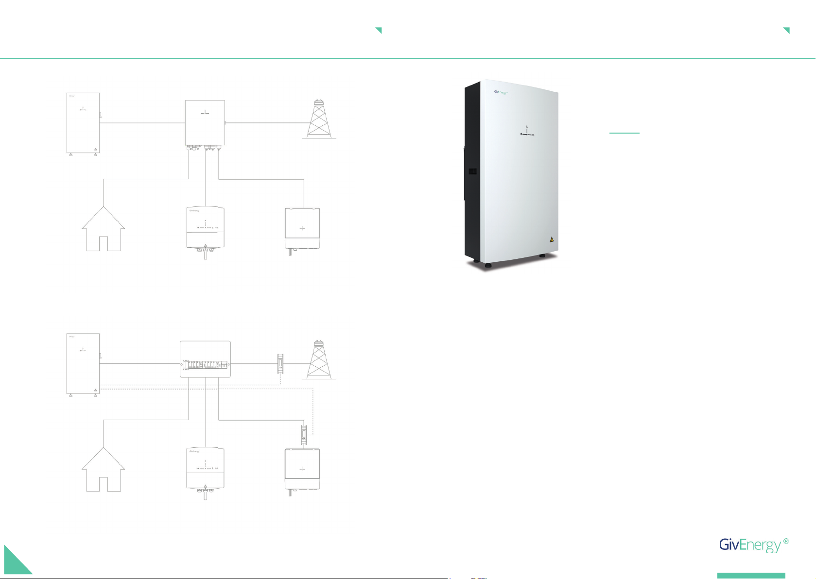
The All in One contains a bidirectional inverter and a 13.5kWh lithium iron phosphate battery. When
used with our Giv-Gateway, the system can provide whole home backup when a power outage occurs.
The system can charge from the grid when prices are cheaper, and export stored generation when
prices are at their peak. The Giv-Gateway interface features connections for a PV inverter, EV charger,
grid and home storage battery.
Storing the All in One and Giv-Gateway
The unit must be stored in its original packaging at temperatures between -40ºC - 70ºC.
Do not stack more than 5 units on top of each other.
If any damaged or missing parts are found, please contact GivEnergy on 1300 448 363 or email
support@givenergy.co.uk immediately and your distributor. Returns must be provided in the original
or equivalent packaging. The Giv-Gateway’s cardboard packaging is recyclable.
02 | AIO AND GIV-GATEWAY
GENERAL INFORMATION
Introduction
All information contained in this booklet refers to the installation and maintenance of GivEnergy’s
All in One and Giv-Gateway. Please retain this manual for future reference.
Legal Disclaimer: This document is the property of GivEnergy, reproduction is prohibited.
Ensure the packaging and product are free from any damage
When unpacking, please check the following:
Packaging Contents
There are no missing accessories from the packaging list
The model and specication of the All in One and Giv-Gateway’s nameplate match the order specications
AIO AND GIV-GATEWAY | 03
General introduction ...................................................................... 03
..............................................................................
System diagram 04
.................................................................All in One Specications 05
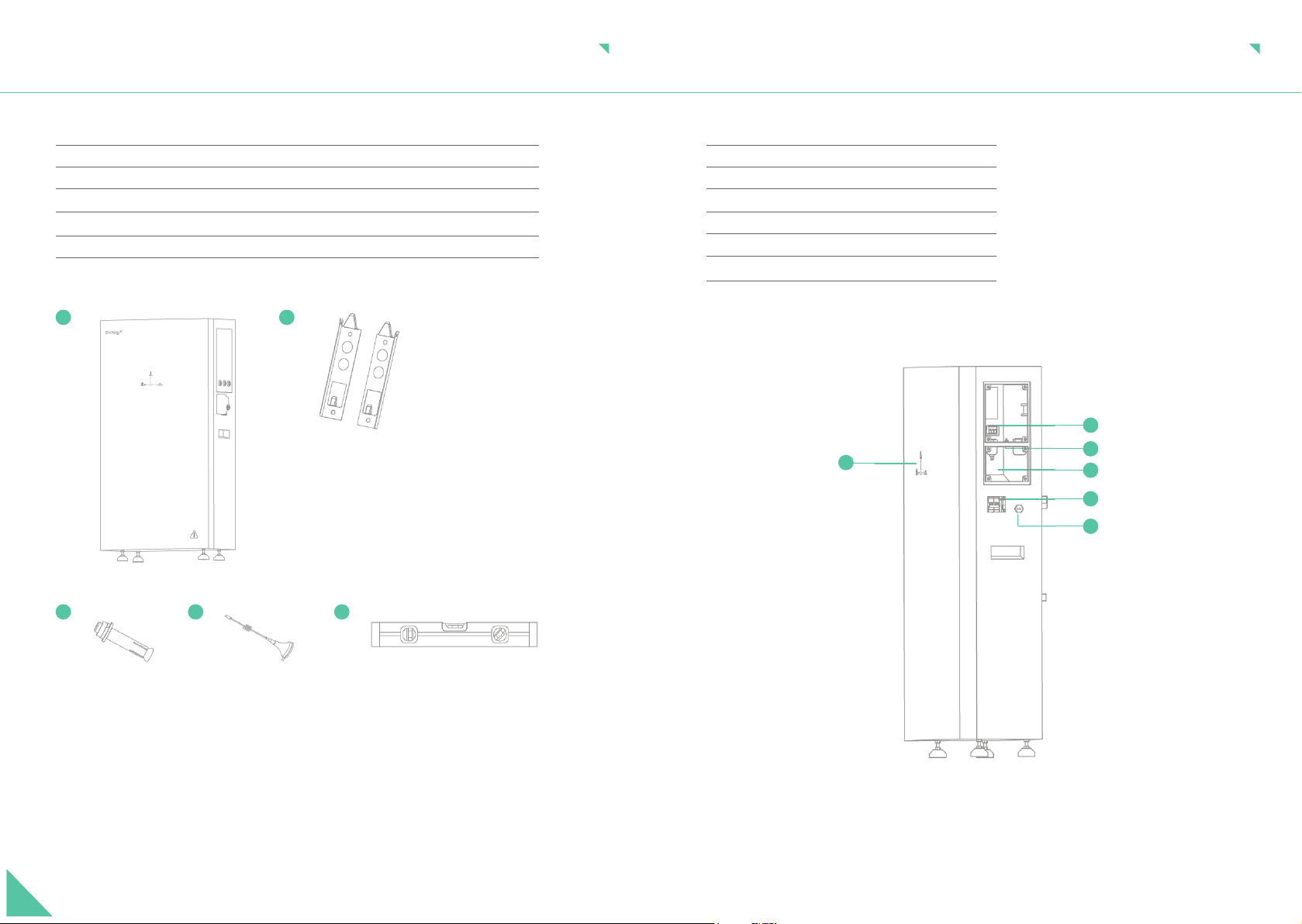
...................................................................All in One box contents 06
...................................................................All in One components 07
........................................................................All in One unboxing 08
.................................................................Installation instructions 09
.........................................................................Safety instructions 10
...........................................................Clearance and maintenance 11
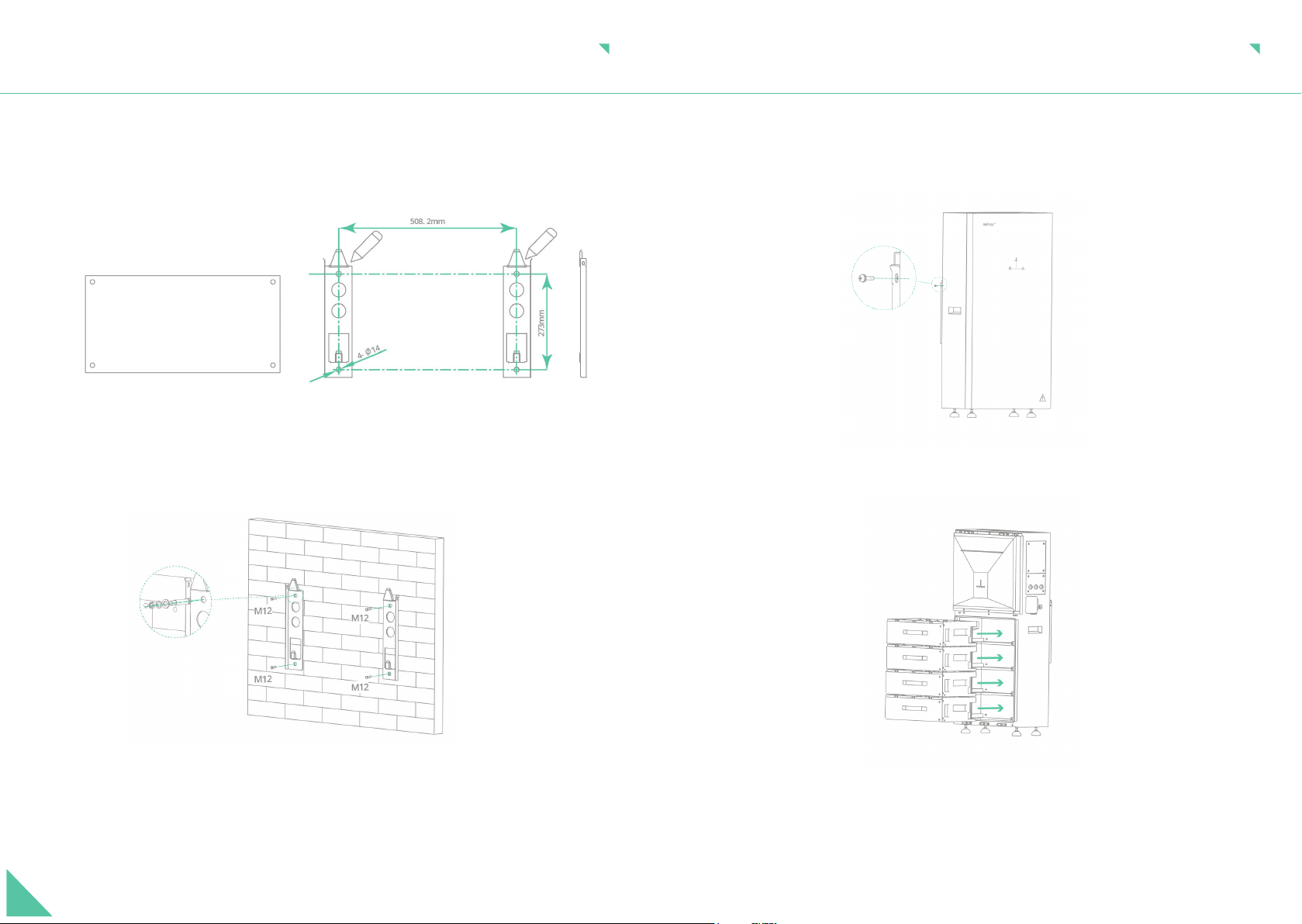
................................................All in One step-by-step installation 12-13
....................................................All in One connections overview 14
...............................................All in One AC utility grid connection 15
............................All in One comms connection with Giv-Gateway 16
.......................
All in One comms connection without Giv-Gateway 17
..............................................................Giv-Gateway specications 18
..............................................................Giv-Gateway box contents 19
.....................................Isolating the main supply to the property 20
...............................................................Giv-Gateway components 21
...........................................................Clearance and maintenance 22
...........................................Giv-Gateway step-by-step installation 23-24
....................................................................
Connections overview 25
..........................................Giv-Gateway AC utility grid connection 26
.....................................Giv-Gateway communication connections 27
............................................Connecting All in One to Giv-Gateway 28
.......................................Start up and shut-down of the All in One 29
............................
Commissioning and decommissioning a system 30
.......................................................Understanding your All in One 31
...................................................
Understanding your Giv-Gateway 32
........................................All in One installation with Giv-Gateway 33
..................................
...................................................................................
..............................................................
All in One installation without Giv-Gateway
Work modes
Manufacturer warranties
34
35
36

SYSTEM DIAGRAM
Giv-Gateway
Consumer unit
With Giv-Gateway
Without Giv-Gateway
All in One
All in One
Load
Load
EV charger
EV charger
PV inverter
PV inverter
Grid
Grid
ID1
ID2
ALL IN ONE SPECIFICATIONS
Primarily working as an on grid system, the
All in One can deliver 7.2kW of peak power (where
permitted) into the home on top of any solar
generation.
Complete with a substantial 13.5kWh useable
battery pack that stores excess generation. Connect
up to 6 systems in parallel, giving 80kWh of useable
storage (coming soon). Featuring a modular design
comprising 4 removable battery packs, allowing for
ease of handling and installation.
A great addition to any smart home
ROBUST AND FLEXIBLE
Speci cations Dimensions
1100H x 280D x 600W (mm)
Warranty
10 years
Model numbers
GIV-AIO-AC-13.5-3.6
GIV-AIO-AC-13.5-4.6
GIV-AIO-AC-13.5-5.0
GIV-AIO-AC-13.5
AC Input Rating
6000W
Weight
173.7 Kg
AC Max. Output Rating
3.6kW / 16 A Peak/continuous
4.6kW / 20 A Peak/continuous
5.0kW / 22 A Peak/continuous
7.2kW / 32A Peak/ 6kW / 27A continuous
Operating temperature
-10oC to 50oC
Depth of Discharge
100%
Connectivity
WiFi, LAN and 4G
Noise Emission (typical)
<30dB
04 | AIO AND GIV-GATEWAY

A
C E
B
D
Item Item Name Qty
All in One UnitA 1
Bracket
Expansion Bolt
WiFi Antenna
Spirit Level
B
C
D
E
2
4
1
1
ALL IN ONE BOX CONTENTS
AF
Item Item Name
Power Flow IndicatorA
AC Supply Terminals
Wi Antenna
DC Circuit breaker
On / Off Switch
Cable entry point
B
C
D
E
F
ALL IN ONE COMPONENTS
C
B
D
E
06 | AIO AND GIV-GATEWAY AIO AND GIV-GATEWAY | 07

ALL IN ONE UNBOXING
Remove top cover from the wooden
crate, ensuring to wear gloves and taking
care when bending the metal tabs.
1.
Remove the foam and then the front
cover of the All in One
3.
Remove the All in One brackets, template,
and accessories and place to one side
2.
Remove bottom waterproof cover of the
All in One
4.
Remove the battery packs, leave to one side5. Remove All in One case from wooden crate
(2 person lift)
6.
and accessories and place to one side
Do not install in direct sunlight or near water sources
Do not use the equipment if there are any deformities, such as bulging or leakages
Do not puncture the equipment
Do not throw the equipment or use forceful impact
Do not attempt to repair the equipment yourself (please call your Approved Installer)
INSTALLATION INSTRUCTIONS
Dos
Don’ts
The system must be installed under a canopy if installing externally unless fully shaded
The feet of the All in One are designed to be above the frost-line at a minimum
of 50mm
You must comply with local battery and inverter installation guidelines and regulations
The system must be installed in an easily accessible location, the status display must
be visible and not obstructed
Please ensure that the wall to be mounted on is suffi cient enough to hold the weight
of the All in One and Giv-Gateway (if tted)
The system must be installed in a well ventilated area, the ambient temperature
should be below 40ºC to ensure optimal operation
Do not use the system if the temperature exceeds 45ºC
The system must be installed vertically with connections always positioned at the
bottom, never install horizontally, and avoid tilting the unit
08 | AIO AND GIV-GATEWAY AIO AND GIV-GATEWAY | 09

Ensure the All in One and Giv-Gateway are always xed to the wall using the mounting bracket
Any errors are shown with a red LED, for full descriptions please refer to the GivEnergy
monitoring portal
Ensure all components are attached securely
Extra care and attention must be taken when installing and maintaining any GivEnergy equipment.
The system is capable of retaining a high voltage, even when disconnected.
SAFETY INSTRUCTIONS
All electrical installations must be carried out by a quali ed and registered electrician and in
accordance with the local wiring regulations
During operation, the heat sink may become hot. Do not touch the heat sink at the sides, or the
top of the inverter when in operation
The system is designed to be connected to the grid; connecting your inverter to a generator or
other power source can result in damage to the inverter or external devices
All GivEnergy equipment must be installed by a GivEnergy approved installer
If any damaged or missing parts are found, please contact GivEnergy on 1300 448 363 or email
support@givenergy.co.uk immediately. Returns must be provided in original or equivalent
packaging, for safe transport please refer to our UN38.3 certi cate
If you suspect something is wrong with the system, contact GivEnergy on 1300 448 363 or email
support@givenergy.co.uk
There must be adequate clearance around the All in One to allow for heat dissipation. The diagram
below illustrates the space required around the system.
CLEARANCE AND MAINTENANCE
When maintaining and cleaning the All in One, the whole system must be powered down. Please
refrain from using cleaning products on the surface of the All in One. Ensure that the heat sink is free
from blockage to allow proper air fl ow. Check that no cables, isolation points, or the casing itself are
physically damaged.
To ensure your All in One operates optimally at all times, annual maintenance checks need to be
carried out. Check for visible damage or discolouration of the switch, and that the cables are intact.
Please ensure that the top of the All in One is not obstructed in any way.
Space Clearance
Maintenance
300mm
250mm
250mm
250mm
250mm
10 | AIO AND GIV-GATEWAY AIO AND GIV-GATEWAY | 11

Place the wall mounting template horizontally onto the wall and mark the position of the bracket
holes. Drill 4 holes at the marked positions, at least 75mm deep.
1.
Fix the mounting bracket to the wall using the expansion bolts or suitable xings. Please note: the
brackets are sided.
2.
ALL IN ONE STEP-BY-STEP INSTALLATION
Re-insert the battery modules into the shelves of the All in One battery compartment. Secure
the battery modules using the xings provided. Re-attach waterproof cover.
Replace the front cover and secure with the screws.
4.
5.
Mount the All in One onto the mounting bracket. Adjust the height of the supporting feet to
ensure the unit is level and attach the securing screws to the brackets, ensuring the weight is
on the feet, not the brackets.
3.
ALL IN ONE STEP-BY-STEP INSTALLATION
12 | AIO AND GIV-GATEWAY AIO AND GIV-GATEWAY | 13

Item Item Name
ALL IN ONE CONNECTIONS OVERVIEW
Communication / networkA
AC SupplyB
B
A
WiFi
All in One communication / network ports
LAN
USB (Dongle) Mode
Giv-Gateway in
Giv-Gateway out
Parallel in
Parallel out
LAN
USB
Dip
switch
WiFi
reset
LC Meter LM
Cable size requirements are dependent on the country of installation, cable run length, and max.
current of the product.
Both side and rear cable entry points are provided. If using rear entry point please ensure the cable is
installed prior to tting the All in One. The AC supply cable should enter through one of the waterproof
glands and pass through the cable entry chamber (labelled below) and connected into the AC supply
terminal block. Strip the outer insulation to 8mm in length of bare copper and connect them to the
terminal block.
ALL IN ONE AC UTILITY GRID CONNECTION
The recommended maximum cable length should not exceed 50m as the resistance of the cable will
consume inverter output power and reduce the inverter effi ciency.
Cable entry
chamber
Power and
comms
14 | AIO AND GIV-GATEWAY AIO AND GIV-GATEWAY | 15

ALL IN ONE COMMS CONNECTION WITH GIV-GATEWAY
To install a single All in One,
connect communication wire
to the socket D in the wiring
compartment of the All in
One.
Please note: The communication cable must be terminated with a
RJ45 plug at either end to connect the All in One to the Giv-Gateway.
Ensure the wiring con guration into the RJ45 is the same both ends,
a cross-over cable will not work. A standard Ethernet Cat5/6 cable
will suffi ce here wired to T-568B standard if doing locally.
Single All in One installation
16 | AIO AND GIV-GATEWAY
ALL IN ONE COMMS CONNECTION WITHOUT GIV-GATEWAY
Giv-Gateway in
Giv-Gateway out
Parallel in
Parallel out
LAN
USB
Dip
switch
WiFi
reset
LC Meter
ID1
+
-
Grid
ID2 (optional)
Generation
ID3 (optional)
Generation
LM
Giv-Gateway in
Meter port
AIO connection
AIO AND GIV-GATEWAY | 17
Grid
Generation

Protection Class
IP65
Max. AC Current
100A
GIV-GATEWAY SPECIFICATIONS
By purchasing the additional Giv-Gateway, the
All in One can provide whole house backup in the
event of a grid failure.
The Giv-Gateway provides seamless switching
between grid and battery ensuring that your
property is always powered. The Giv-Gateway
also facilitates a connection point for your solar
PV system by allowing it to continue to generate
energy even without a grid supply.
A great companion to the AIO
WHOLE HOME BACKUP
Speci cations Dimensions
410H x 190D x 370W (mm)
Nominal AC Power
18.4 kW
Weight
12.75 K g
Rated Grid Frequency
50/60±5Hz
Warranty
10 years
Model number
GIV-AIO-GW1
A
C E
F
B
D
G
Item Item Name Qty
Giv-GatewayA 1
Bracket
Mounting screw
Wall plug
Antenna
Key
M6 x 12 Bracket Screw
B
C
D
E
F
G
1
2
2
1
1
4
GIV-GATEWAY BOX CONTENTS
18 | AIO AND GIV-GATEWAY AIO AND GIV-GATEWAY | 19

ISOLATING THE MAIN SUPPLY TO THE PROPERTY
Before installing the Giv-Gateway, make sure that the whole house is isolated from the main supply.
Once isolated, please test to ensure that no voltage is present to the property before disconnecting
the main supply cable from the consumer unit. The Giv-Gateway should be installed between the
customer’s supply meter and the consumer unit.
C
Item Item Name
MCB, RCDA
CT, RS485, LAN, CAN,
Grid / PV Meter and LoRa (spare)
B
C
GIV-GATEWAY COMPONENTS
B
A
20 | AIO AND GIV-GATEWAY AIO AND GIV-GATEWAY | 21

There must be adequate clearance around the Giv-Gateway. The diagram below illustrates the
space required around the system.
CLEARANCE AND MAINTENANCE
When maintaining and cleaning the Giv-Gateway, please refrain from using cleaning products on its
surface.
To ensure your Giv-Gateway operates optimally at all times, annual maintenance checks need to be
carried out. Check for visible damage or discolouration of the switches, and that the cables are intact.
Please ensure that the top of the Giv-Gateway is not obstructed in any way.
Space Clearance
Maintenance
200mm
200mm
200mm
200mm
200mm
200mm
1.
GIV-GATEWAY STEP-BY-STEP INSTALLATION
Fix the mounting bracket to the wall using the xings provided, or other suitable xings.
Place the wall mounting bracket horizontally onto the wall and mark the position of the bracket
holes. Drill 2 holes at the marked positions, at least 75mm deep.
2.
22 | AIO AND GIV-GATEWAY AIO AND GIV-GATEWAY | 23

3. Fix the Giv-Gateway to the mounting bracket and secure with the xings provided. Ensure
there is adequate clearance space.
GIV-GATEWAY STEP-BY-STEP INSTALLATION
Item Item Name
CONNECTIONS OVERVIEW
LoRa connection Module (spare)A
PV meter (ID2)B
Grid meter (ID1)C
AC supply (in)E
DLoad (house supply)
F All in One supply
GPV inverter supply
H
I
J
EV charger (spare)
All in One parallel connection (coming soon)
Grid bypass switch
A
B
D EC
F G
I
J
H
24 | AIO AND GIV-GATEWAY AIO AND GIV-GATEWAY | 25

GIV-GATEWAY AC UTILITY GRID CONNECTION
To All in One
(6mm2minimum)
Breaker F
- AC supply in (16-25mm2tails)
Breaker A
Breaker B
Breaker C (optional)
Earthing cable to earth rod
(mandatory)
Breaker E
Breaker D - AC supply out to home
(16-25mm2tails)
Breaker A - Single All in One connection
The power wires for All in One connection should be at least 6mm². Strip the wire insulation
for 8mm wiring connection.
Breaker E - Bypass MCB
The bypass switch redirects grid power directly to the house, bypassing the Giv-Gateway.
Breaker D - Loads connection
The maximum load current is 80A, so the load wires should be at least 16mm². Strip the wire
insulation for 8mm to connect to this load breaker.
Breaker F - Grid connection
The maximum load current is 100A, so the load wires should be at least 16mm². Strip the wire
insulation for 8mm to connect to this load breaker.
Breaker C - EV charger connection
The maximum load current is 32A, so the load wires should be at least 6mm². Strip the wire
insulation for 8mm for wire connection.
Breaker B - PV inverter connection
The meter tails between the meter position and Givenergy Gateway should not be longer than 3
metres. If the length is more than 3 metres, you should install an additional protective device at the
nearest point to the supply inside the customer’s premises, as speci ed in the current IEE Wiring
Regulations.
GIV-GATEWAY COMMUNICATION CONNECTIONS
WiFi
Gateway communication/network ports
Comms to All in One
DRM
USB
LAN
Dip switch
RS485
AC CTLOAD CT PV CT SPD
PV RS485
Meter RS485
LAN USB (Dongle) Mode
26 | AIO AND GIV-GATEWAY AIO AND GIV-GATEWAY | 27

CONNECTING ALL IN ONE TO GIV-GATEWAY
AC supply wiring
Communication wiring
Please note: Remove bottom connections cover prior to wiring, and then replace once complete.
START-UP AND SHUT-DOWN OF THE ALL IN ONE
Start-Up Procedure
Shutdown Procedure
Connect the AC circuit breaker, ensure that the system is powered and commissioned
using the portal/App. Ensure that the grid power is reading identical to that of the mid
approved meter (this can be found on the screen of the grid meter)
Ensure connection covers are in place
2.
1.
Turn off the battery (On/Off switch)1.
Turn off the AC circuit breaker to prevent it from being reactivated (AIO MCB)
2.
Turn on the battery breaker (DC MCB)3.
Turn off the battery breaker to prevent it from being reactivated (DC MCB)
3.
The inverter will start automatically when the battery voltage is higher than 270V DC or the
Giv-Gateway provides AC voltage to the All in One
Please note: House load will not be present unless the All in One is online, or BYPASS breaker
is activated. BYPASS must not be kept on.
5.
Check the inverter operating status4.
Wait until all LEDs have gone out. The All in One is now shut down
5.
4. Turn on the battery (On/Off switch)
28 | AIO AND GIV-GATEWAY AIO AND GIV-GATEWAY | 29

COMMISSIONING AND DECOMMISSIONING A SYSTEM
All systems must be commissioned to ensure correct battery and meter communications, as well
as connection to the online portal.
Check that all the wires are securely connected before the battery breaker and the AC isolator is
switched on. You MUST set the parameters of the battery according to your battery system.
Note: Without commissioning, the system may not operate correctly.
Either sign into the online portal at https://portal.givenergy.cloud, or the GivEnergy app with
your GivEnergy Engineer login. If you are a rst time user, and you do not have an account or
Engineer login, please consult your supplier to get this set up.
Sign into the GivEnergy app and follow the in-app instructions.
To decommission the system please contact GivEnergy either by phone on 1300 448 363 or email
at support@givenergy.co.uk.
Accessing the Commissioning Portal/GivEnergy app
Setting up the internet connection
Decommissioning the system
To download a fully illustrated guide, please visit our Knowledge Base at www.givenergy.co.uk
UNDERSTANDING YOUR ALL IN ONE
Battery
Home demand
Device status
Grid
When the battery is being charged,
the arrows will point towards the
battery pack. When the battery is
discharging, the arrows will point
towards the inverter.
This is a calculation made by our
smart energy management system
and is lit up when a load is detected
within the property.
Normal
The system is in waiting
Charging or discharging error
(reboot the unit)
Fault (contact GivEnergy)
Firmware upgrade
Green (solid)
Green (fl ashing)
Yellow
Red
Green/Red (fl ashing)
When energy is being imported
from the grid, the arrows pointing
towards the centre will be lit. When
energy is being exported to the
grid, the arrows pointing towards
the grid will be lit.
30 | AIO AND GIV-GATEWAY AIO AND GIV-GATEWAY | 31

UNDERSTANDING YOUR GIV-GATEWAY
Battery
Home demand Grid
When the battery is being charged,
the arrows will point towards the
battery pack. When the battery is
discharging, the arrows will point
towards the inverter.
This is a calculation made by our
smart energy management system
and is lit up when a load is detected
within the property.
When energy is being imported
from the grid, the arrows pointing
towards the centre will be lit. When
energy is being exported to the
grid, the arrows pointing towards
the grid will be lit.
Device status
Normal
The system is in waiting
Charging or discharging error
(reboot the unit)
Fault (contact GivEnergy)
Firmware upgrade
Green (solid)
Green (fl ashing)
Yellow
Red
Green/Red (fl ashing)
ALL IN ONE INSTALLATION WITH GIV-GATEWAY
Note: An earthing rod MUST be installed.
Integral ID1 & 2
Integral grid relay
(with hard bypass)
MUST be off
Integral CT
(Load)
Integral ID2
PV Inverter
Consumer unit
CANBus
Comms
GEM120 - ID1
GEM120 - ID2
32 | AIO AND GIV-GATEWAY AIO AND GIV-GATEWAY | 33

This is prioritised to charge the battery utilising excess solar generation, when energy
is cheaper, greener, and cleaner. The battery will start to discharge outside of the peak
generating hours when energy is more expensive.
Solar Charging
The system has the ability to be used in the event of a power cut. To utilise this the All in
One must be connected to a Giv-Gateway. In the event of a power cut the Giv-Gateway will
seamlessly switch over to battery to power the whole home.
Back Up / Island Mode
Remotely disconnect your home from the grid at the push of a button using the
GivEnergy App or Online Monitoring Portal.
Off Grid Operation
This is prioritised to charge the battery during off peak times when energy is cheaper,
greener, and cleaner. The battery will start to discharge outside of the off peak time when
energy is more expensive.
Off Peak Charging
WORK MODES
AIO AND GIV-GATEWAY | 35
ALL IN ONE INSTALLATION WITHOUT GIV-GATEWAY
Note: An earthing rod MUST be installed.
Integral CT
(Load)
ID2 ID1
PV Inverter
Consumer unit
34 | AIO AND GIV-GATEWAY

MANUFACTURER WARRANTIES
The All in One and Giv-Gateway are covered by 10-year warranties.
Products Covered
Legal Disclaimer: This document is the property of GivEnergy, reproduction is prohibited.
10 years
Giv-Gateway
10 years
All in One 13.5
Products Covered
36 | AIO AND GIV-GATEWAY

www.givenergy.co.uk
Other manuals for GIV-AIO-13.5
1
This manual suits for next models
4
Table of contents
Other GivEnergy Gateway manuals
Popular Gateway manuals by other brands

Siemens
Siemens SIMATIC IOT Quick install guide

EMS
EMS CG-ARM7/GTI Series user manual

Rohde & Schwarz Topex
Rohde & Schwarz Topex MobiLink IP user manual

Moxa Technologies
Moxa Technologies MGate 4101-MB-PBS-T user manual

NetComm
NetComm SmartVoice V404 Specifications

Allied Telesis
Allied Telesis AT-iMG606BD Specifications