SGC Smartuner SG-230 User manual

SG-230
Smartuner
®
Microprocessor Controlled Automatic Antenna Coupler
Installation and Operations Manual
Getting the most from every watt of HF-SSB Power

Globally, HF-SSB has literally changed the world. For a minimal investment, it has allowed millions of people - often in
amazingly remote settings, often in emergency conditions - to reliably bounce clear voice and data signals across a state,
across a continent, over an ocean, or around the world. Without satellites, relay stations, cellular nets, stadium sized anten-
nas or huge user fees. Just some fine equipment, a smart operator and nature's own ionosphere make this possible.
For nearly 30 years, the perfection of HF SSB has been the focus and the life of our company. Our efforts have not gone
unnoticed. Today, SGC is a prominent choice of leading corporations, governments, relief agencies, paramilitary organiza-
tions, mariners, aviators, explorers, and
scientists - all over the world. They trust
our engineering and they value our expe-
rience.
A vital part of our company's strate-
gy centers around new product develop-
ment, with an emphasis on providing
quality equipment which remains rugged,
reliable and competitively priced. We are
focused on providing customer service of
the highest standard. Our commitment is
to product training and comprehensive
after sales support. Today, SGC is recog-
nized as a world class designer and manufacturer of HF SSB communications products.
At SGC we build communications power tools. Next generation HF-SSB radios, antennas, amplifiers and coupler sys-
tems that squeeze more range and clarity out of every watt of HF SSB communications power, are the technology and innova-
tions that have helped SGC emerge as a cutting edge player in the expanding world of HF-SSB.
Actually, SGC was the first company to perfect and mass produce solid-state HF SSB radios, more than 20 years ago.
Today, our focus is an ever higher level of HF SSB refinement and performance. All focused on creating HF SSB voice and
data communications systems that are so user friendly
and so powerful, they allow every SGC user to easily
lock in the world. SGC - HF SSB Power Tools! Pierre B. Goral, President
HF-SSB COMMUNICATIONS:
THE POWER TO LOCK IN THE WORLD.

SG-230
ANTENNA
COUPLER
Installation and Operations Manual
Prepared: September 1998
3
© 1998 SGC Inc
SG-230 Manual
SGC Inc. SGC Building, 13737 S.E. 26th St. Bellevue, WA 98005 USA
P.O. Box 3526, 98009 Fax: 425-746-6384 Tel: 425- 746-6310 or 1-800-259 7331
CCAAUUTTIIOONN::Carefully read the ÒQuick StartÓ on the fol-
lowing page and all pertinent sections of this manual
prior to operating your Smartuner for the first time. This
unit will provide outstanding service if you follow the
detailed recommendations within this manual.
4
QQuuiicckkSSttaarrttGGuuiiddee
To quickly install your antenna coupler you will need the following:
1. An HF radio with 10 to 150 watts output.
2. An HF antenna with a single wire feed (not coax fed).
Minimum length of 8 feet (to 3.5 MHz) or 23 feet (1.8 MHz).
3. A good ground (counterpoise) for the antenna and coupler
4. +12 VDC and ground for the coupler.
5. An LED or other indicating device. (Optional)
Connections:
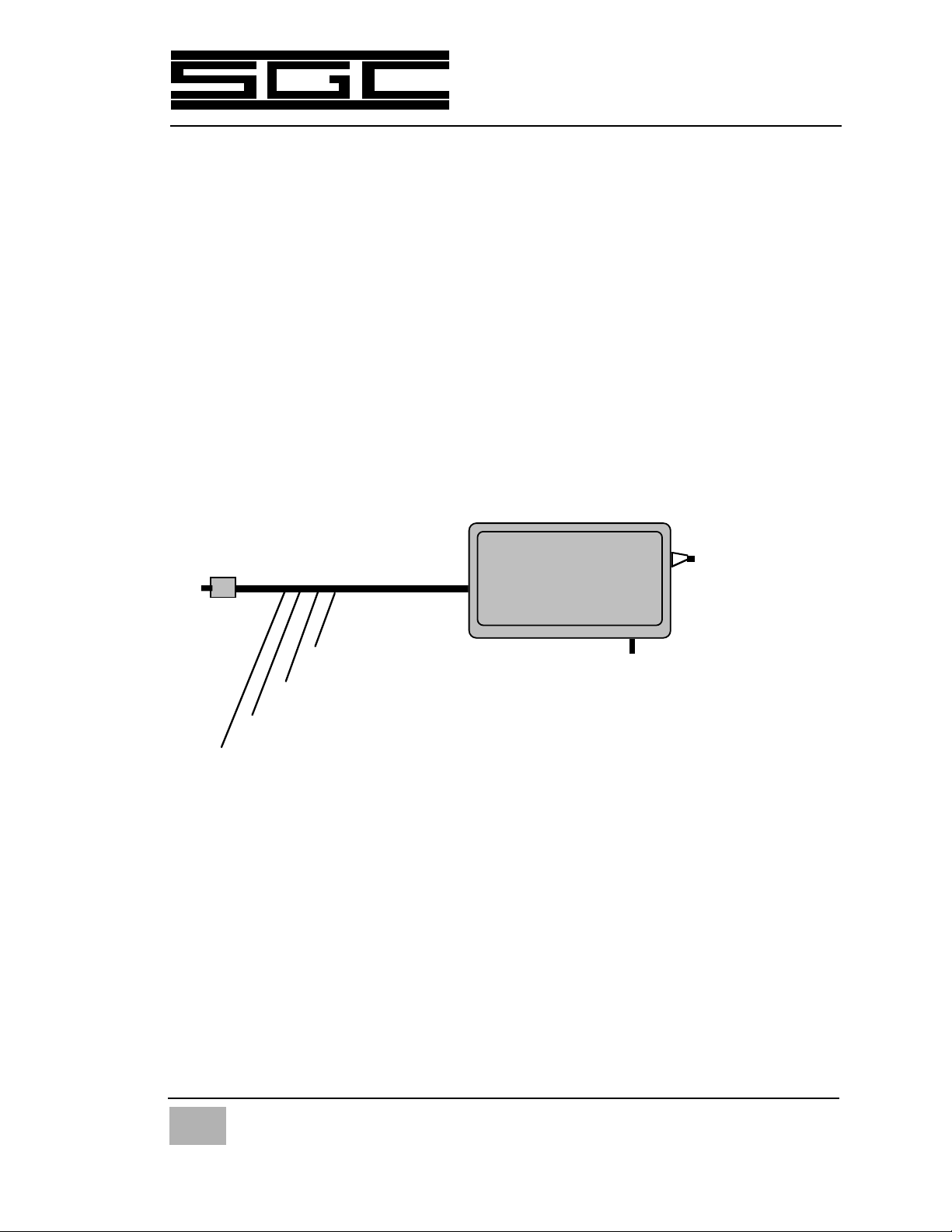
Connect the Smartuner as shown in the following diagram:
Operation:
1. Turn on Radio. Apply 12 VDC power to the coupler.
2. As power is applied, coupler should make one "click" sound.
3. Coupler should come up in the bypass (untuned) state.
4. To tune, speak normally, whistle or use CW.
5. Tuning should be done at full power. Clicking is heard.
6. When tuned, clicking stops and Black/White wire goes low.
SGC Inc. SGC Building, 13737 S.E. 26th St. Bellevue, WA 98005 USA
P.O. Box 3526, 98009 Fax: 425-746-6384 Tel: 425- 746-6310 or 1-800-259 7331
© 1998 SGC Inc
SG-230 Manual
TO TRANSMITTER (10-150 w)
Black: DC Ground
Red: +12 VDC coupler power
Red/White: Optional SmartLock lock/reset line. (+12 VDC locks, momentary
groundresets)
Black/White: Optional remote tuned indicator. Goes low when coupler is tuned.
Single wire
ANTENNA
GROUND (Counterpoise)

TTaabblleeooffCCoonntteennttss
1.0 General information 8
1.1 Experience Levels of Users 8
1.2 What is an Antenna Coupler? 8
1.3 Overall Description 9
1.4 Coupler Network Configuration 11
S
1.5 Operation Indicators 11
1.6 Mechanical Configuration 12
1.7 Marine Installation 13
1.8 Desert and High Temperature Mounting 13
1.9 Extremely Cold Temperatures 13
1.10 Remote Installations 14
1.11 Upgrade Sequences 15
2.0 Specifications - SG-230 16
2.1 Accessories 16
2.2 Recommended SGC Antennas 17
3.0 Parts Furnished 17
3.1 User Supplied Items 17
3.2 Technical Support 18
4.0 Antenna Types 19
4.1 Selection 19
4.2 Whip Antenna -2.5 - 3.0 METERS 20
4.3 Whip Antenna - 7.0 -8.5 meter (23 ft) 20
4.4 Longwire Antenna - 23 meter (75 ft) & 46 meter (150 ft) 20
4.5 Backstay Antennas 20
5.0 Typical Installations 21
5.1 Apartment Loop Antenna 27
5.2 Recreational Vehicle (RV) Antennas 29
5.3 Low Profile, Hidden and Covert Antennas 30
5.4 Emergency Antennas 32
5.5 Kite Antenna 32
5.6 Tactical Installations 32
5.7 Tactical Antenna Supports 33
5.8 Tactical Grounds and Counterpoises 33
5
© 1998 SGC Inc
SG-230 Manual
SGC Inc. SGC Building, 13737 S.E. 26th St. Bellevue, WA 98005 USA
P.O. Box 3526, 98009 Fax: 425-746-6384 Tel: 425- 746-6310 or 1-800-259 7331

6
6.0 General Notes on Antennas and Couplers 34
6.1 Steps to Antenna Installation 35
6.2 Antenna Location 36
6.3 Ground Systems - General 37
6.3.1 Vehicle Grounds 37
6.3.2 Marine Grounds 37
6.3.3 Base Station Grounds 39
6.4 Corrosion 40
6.5 Antenna Tuner Mounting 40
6.6 Antenna Connection 40
7.0 Installation Procedures 41
7.1 Installation with SG-2000 41
7.2 Installation on all Radios 41
7.3 Remote Tune Indicator LED for External Use 43
7.4 Weatherdeck Mounting 44
7.5 Alternate Electrical Checkout 45
7.6 Alternate Electrical Checkout 46
7.7 Coupler Configuration 50
7.8 Schematic Diagrams 50
7.9 Tuning Process 50
7.10 Impedance Detector 51
7.11 VSWR Detector 51
7.12 Phase Detector 52
7.13 The Control Device 52
7.14 Initialization 52
7.15 Information Read 53
7.16 Storing Memory 53
7.17 Bypass Operation, Jumpers 54
8.0 Optional Smartlock 55
9.0 Tuning Process and Options 56
9.1 Program Description 57
9.2 Tuning Algorithms or Paths 58
9.3 Antenna Too Short 59
9.4 Antenna Too Long 60
9.5 J-2 - Tuning Elements out During Receive 60
SGC Inc. SGC Building, 13737 S.E. 26th St. Bellevue, WA 98005 USA
P.O. Box 3526, 98009 Fax: 425-746-6384 Tel: 425- 746-6310 or 1-800-259 7331
© 1998 SGC Inc
SG-230 Manual

9.6 J-3 - Tune From Memory 61
10.0 Troubleshooting the SG-230 61
10.1 Ground Faults 62
10.2 Antenna Faults 63
10.3 Transmitter Faults 65
10.4 A Final Pointer on Troubleshooting 65
Warranty Information 66
Schematics 67
Appendix - QMS System A-1
SG-303 Antenna Brochure
SG-307 Antenna Brochure
QMS Antenna Coupler System Brochure
QMS-7 Antenna Coupler System Brochure
7
© 1998 SGC Inc
SG-230 Manual
SGC Inc. SGC Building, 13737 S.E. 26th St. Bellevue, WA 98005 USA
P.O. Box 3526, 98009 Fax: 425-746-6384 Tel: 425- 746-6310 or 1-800-259 7331

8
11..00GGeenneerraallIInnffoorrmmaattiioonn
The SG-230 is believed to be the most widely used antenna coupler in the world.
The Smartunerª reputation has grown to legend status because it is a very
simple to use and highly reliable piece of electronic equipment. A Smartuner
will provide maximum transfer of radio energy from any HF transmitter to
any end fed HF antenna within the frequency and power limits of its specifications.
This document is designed to guide the SG-230 Smartuner user through instal-
lation and operation of the unit. This document will also recommend various
steps which may be undertaken in the field to provide correct operation of the
SG-230 should difficulty be encountered. Smartuners are extraordinarily reli-
able. But you should be aware that there are scores of fine points to any HF
installation which are easily overlooked and may cause difficulty. Our goal in
this manual is to help you quickly obtain the best possible performance from
your HF radio installation. By reading this manual carefully, you can avoid
most of the pitfalls which can degrade the performance of your HF system.
11..11EExxppeerriieenncceeLLeevveellssooffUUsseerrss
The Smartuner may be installed successfully by anyone willing to review this
manual. However, if you are inexperienced in HF radio installation and opera-
tion, do not be shy about seeking advice from people with more experience
than your own. This will help you achieve good results quickly and with a
minimum of frustration. Even the most experienced professional HF users will
occasionally run into difficulty.
Regardless of the level of your experience, SGC stands ready to offer you
installation suggestions and help you resolve any aspect of Smartuner opera-
tion which is not entirely satisfactory. If you have a specific question, please
send us a fax at our Bellevue, Washington (USA) headquarters. The number is
(425) 746-6384. If you require telephone assistance, please call us at
(425) 746-6310 during business hours, 8:00 Am to 5:00 PM Pacific Time.
11..22WWhhaattiissaannAAnntteennnnaaCCoouupplleerr??
Antenna "couplers" are placed at the antenna and match conditions of the
antenna to the feed line in a very precise manner. Antenna "tuners", on the
other hand, are generally located at the transmitter output at the radio end of
the coaxial feed line. Do not be confused by the term "coupler" or "tuner".
¥ Tuners placed at the transmitter allow substantial losses in feed
lines to be corrected in order to fool a transmitter into working
SGC Inc. SGC Building, 13737 S.E. 26th St. Bellevue, WA 98005 USA
P.O. Box 3526, 98009 Fax: 425-746-6384 Tel: 425- 746-6310 or 1-800-259 7331
© 1998 SGC Inc
SG-230 Manual

correctly. The losses are dissipated through heat or to ground.
¥ A coupler installed at the antenna eliminates these losses by
providing a proper match of the antenna to the feed line. The
Smartuner is a true antenna coupler.
There are several key points which we will emphasize throughout this man-
ual which will result in the best possible operation of your Smartuner.
These include:
¥ The coupler must be located at the
antenna
.
¥ No coax may be connected to the coupler output.
¥ Make sure the coupler has a clean 12 VDC power supply.
¥ The ground system must always be
larger
than the antenna.
¥ The antenna wire should be of the largest gauge practical.
¥ Capacitance at the coupler output must be minimal.
¥ Insure the antenna is of sufficient length for your lowest
operating frequency.
Strictly observing these basic rules will insure good operations under the
widest range of conditions.
This manual should be thoroughly studied if you plan to have the best possi-
ble signal and most reliable operation of your HF system.
11..33OOvveerraallllDDeessccrriippttiioonn
The SG-230 is a general purpose coupler which can be operated with any
type of radio and almost any type of antenna configuration. The coupler
network configuration is of an ¹or L type; it automatically selects appropri-
9
© 1998 SGC Inc
SG-230 Manual
SGC Inc. SGC Building, 13737 S.E. 26th St. Bellevue, WA 98005 USA
P.O. Box 3526, 98009 Fax: 425-746-6384 Tel: 425- 746-6310 or 1-800-259 7331
PLEASE MAKE NOTE OF THE FOLLOWING INFORMATION FOR YOUR RECORDS:
Date unit was Purchased: _______/_______/_______
Dealer from whom purchased: ___________________________
Date installed: _______/_______/_______
Type of antenna used: ___________________________________
10
ate algorithms that have been set from the internal coupler measurement, and
reads and feeds this information back to the microprocessor. The initial (first
time) tuning may take several milliseconds to a few seconds depending on the
complexity of the tuning process for a special antenna configuration. After
tuning the first time for a specific frequency and antenna, this information is
entered in the non-volatile computer memory which will store up to 500 tun-
ing solutions. When the same conditions are encountered again, re-tuning is
accomplished within 10 milliseconds by first recalling the information from
the memory. Special software has been designed by SGC to allow accurate and
fine tuning of the coupler. For software description, refer to the MicroTuneª
section of the manual.
If antenna conditions or transmitter conditions have changed since the
information was stored into memory, new information is calculated and a new
tuning solution derived. This new information is stored to memory for future
reference. TThheeSSmmaarrttuunneerrwwiillllaallwwaayyssllooookkffoorrtthheebbeessttppoossssiibbllee
ttuunniinnggssoolluuttiioonnaannddwwiilllliimmpprroovveeeexxiissttiinnggttuunniinnggssoolluuttiioonnsswwhheenn--
eevveerrppoossssiibbllee..
The SG-230 may be bypassed and your antenna used as a broadband receiving
antenna. To do this, turn off the power to the coupler for 2 seconds and then
turn it back on. In this situation, the coupler is reset to stand-by waiting for
the first RF power to be transmitted before providing a tuning solution. In the
stand-by mode, the antenna bypasses tuning elements and connects the
antenna directly to the receiver with no tuning elements engaged. This
allows for receiving signals throughout the HF range.
The coupler will re-tune or hunt if the input to the coupler drops below 10.5
VDC. This situation may occur if a marginal battery is used or if you are trans-
SGC Inc. SGC Building, 13737 S.E. 26th St. Bellevue, WA 98005 USA
P.O. Box 3526, 98009 Fax: 425-746-6384 Tel: 425- 746-6310 or 1-800-259 7331
© 1998 SGC Inc
SG-230 Manual
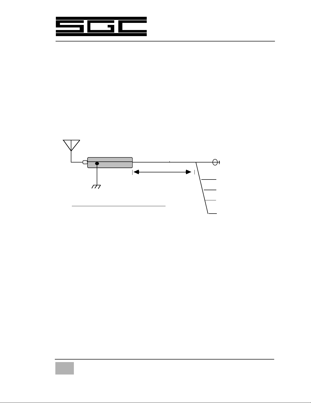
Red +12 VDC
Blk - Ground
Blk/Wht - Remote
Tuned Indicator
Red/Wht - SmartLock
control line
Wire antenna
SG-230 SMARTUNER
Large Ground (counterpoise) system
9 feet (2.8 mtr)
DIAGRAM OF SMARTUNER INSTALLATION
To Transmitter
PL-259
(side view)

mitting at high power with an inadequate power supply or battery. Batteries
must be fully charged for proper operation and large gauge wiring to the
transmitter and coupler must be used to avoid retuning.
If broadband operation is required during scanning operations, jumper J-2 on
the printed circuit board inside the coupler may be set to the "YES" mode. This
will bypass tuning elements on receive. Jumper J-2 is located near IC-7 on the
printed circuit board.
In some cases, it may be desirable to re-tune the coupler and bypass the memo-
ry information. The coupler will store 500 tuning solutions in non-volatile
memory. However, if you wish to bypass the recalled tuning solutions, place
jumper J-3, located near IC-7 on the printed circuit board, to the "NO" position.
Many people wonder what happens when 500 tuning solutions are used. You
don't need to worry about this condition as the Smartuner will over-write pre-
vious tuning solutions as new information is calculated. The Smartuner con-
stantly "learns" changing antenna and radio conditions and constantly
updates its memory without the operator having to do anything. That's what
we mean when we say the Smartuner is smart.
11..44CCoouupplleerrNNeettwwoorrkkCCoonnffiigguurraattiioonn
The coupler network configuration is designed with 64 different input capaci-
tor values, 32 output capacitor values and 2516 inductor values, thus providing
about a half million different ¹or L configurations. The coupler requires an
input of 5 to 150 watts to operate. The unit operates on 12 volts and can be
optionally supplied to operate at 24 VDC. The 24 VDC option may be installed in
the field. Please contact your dealer or SGC and order Part Number 54-52.
11..55OOppeerraattiioonnIInnddiiccaattoorrss
If desired, a remote tuned indicator LED may be connected between the +12
VDC power source and the remote tuned indicator line (Black/white wire). The
remote tuned indicator wire goes low (I.E. becomes grounded) when the
coupler is tuned.
Remember when you are hooking up the remote tuned indicator line that it
goes to ground when the coupler is tuned. In other words, the LED goes
between the black/white wire and the +12 VDC supply.
This coupler tuned indicator is also built into the SmartLockª antenna coupler
control unit along with other indicators. This device will be discussed later in
this manual.
11
© 1998 SGC Inc
SG-230 Manual
SGC Inc. SGC Building, 13737 S.E. 26th St. Bellevue, WA 98005 USA
P.O. Box 3526, 98009 Fax: 425-746-6384 Tel: 425- 746-6310 or 1-800-259 7331
12
Operational status of the coupler and the onboard computer's tuning decisions
is displayed by 7 LED's, which are located on the control computer cover on
the main printed circuit board (PCB). These indicators are only visible when
the cover of the coupler is removed. The function that each LED indicates is
described in Section 7 of this manual. These 7 LED's are not designed to be
interpreted by other than factory and trained service personnel.
11..66MMeecchhaanniiccaallDDeessiiggnn
The SG-230 is supplied in a weather proof case with two mounting brackets. RF
and DC power are supplied to the unit through the same cable. This special
cable consists of a 50 ohm coaxial cable and four conductors. The four con-
ductor wires are for the ground, the positive power lead, the optional
SmartLock control and optional LED indicator.
The SG-230 antenna coupler's weatherproof case is designed to withstand the
environmental conditions encountered aboard ship when mounted on the
weatherdecks. The internal construction is designed to withstand the shock
and vibration of marine service. Corrosion-resistant hardware and passive
alloys are employed throughout. We do not recommend opening the
Smartuner case unless it is necessary. For 99% of installations, the factory set-
tings for jumpers will be correct. The coupler must be installed in an area not
directly exposed to the sunshine or rain. Should you have occasion to open the
case, it must be re-sealed under low humidity (below 35%) and care used to
SGC Inc. SGC Building, 13737 S.E. 26th St. Bellevue, WA 98005 USA
P.O. Box 3526, 98009 Fax: 425-746-6384 Tel: 425- 746-6310 or 1-800-259 7331
© 1998 SGC Inc
SG-230 Manual
CAUTION:
Dangerous high voltages exist inside the Smartuner when it is oper-
ated with an HF transmitter. High RF voltages in excess of 10 kv
may be expected in normal operation of this unit. In addition to
shock hazard, these RF voltages may produce burns which are very
painful if you come in contact with exposed components. Therefore,
DO NOT operate without the cover secured in place unless you are a
well experienced radio technician or engineer.
As a matter of good installation and engineering practice, exposed
metal antenna elements should be located in such a manner as to
prevent accidental contact with people (especially young children),
pets, and small animals.

ensure the gasket which seals the unit is placed properly to maintain water-
tight integrity of the unit.
Although the Smartuner is built very solidly, it is good installation practice
to provide additional protection from the elements.
SGC makes the following recommendations:
11..77MMaarriinneeMMoouunnttiinngg
The Smartuner should be located inside the house or under the aft lazarette
on a sailboat. On power boats, the coupler may be mounted outside, but an
addition protective housing is recommended. The preferred installation if
vertical is with the standoff insulator pointing upward.
A stuffing gland for the RF and DC cables is provided on the lower edge of the
weather housing, along with a 1/4-20 stainless steel ground stud. The anten-
na connects to the ceramic insulator on the top of the weather housing.
The SG-230 may be mounted in any position including inverted without any
degradation of performance. If the coupler is to be exposed to long periods
of high vibration, such as aboard helicopters or tug boats, installation of the
optional shock mounting is recommended.
11..88DDeesseerrttaannddHHiigghhTTeemmppeerraattuurreeIInnssttaallllaattiioonnss
The Smartuner may be used in very hot climates on a continuous basis if
some additional protection from direct sunlight is provided. The best pro-
tection for a mobile installation is provided by the QMS (Quick Mounting
System) which keeps the antenna coupler outside of a vehicle.
Temperatures inside a vehicle may exceed 212 degrees F (100 C). If a QMS is
not used, it is very desirable to keep the coupler in the shade if possible.
Please refer to the diagram in the following section.
11..99EExxttrreemmeellyyCCoollddTTeemmppeerraattuurreeIInnssttaallllaattiioonnss
Your Smartuner will operate down to specified temperatures. We recom-
mend placing the Smartuner under some kind of housing other than the
case to prevent heavy build up of ice. If you are mounting on a tower in a
hot or cold climate, placing a plastic wastebasket (such as those made by
Rubbermaidª) are excellent weather covers and cost only a few dollars.
13
© 1998 SGC Inc
SG-230 Manual
SGC Inc. SGC Building, 13737 S.E. 26th St. Bellevue, WA 98005 USA
P.O. Box 3526, 98009 Fax: 425-746-6384 Tel: 425- 746-6310 or 1-800-259 7331
14
11..1100RReemmootteeIInnssttaallllaattiioonnss
The SG-230 is supplied with 9 feet of cable standard. SGC has two standard
lengths of antenna extension cable available in the event you need to mount
the cable farther than 9 feet from the transmitter. A 25 foot extension cable is
available (SGC Part # 54-61) as is a 50 foot cable (SGC Part # 54-62).
If you need to install the antenna coupler more than 50 feet from the trans-
mitter site, up to 2 extension cables may be used for a total of 75 or 100 feet.
However, SGC does not recommend installing the Smartuner more than 100
feet from the transmitter because two losses must be considered.
¥ The first loss in long distance installations is normal attenuation of the
radio signal coming from the antenna to the radio via the coax. As you may be
aware, the longer the coaxial cable run, the higher the loss will be. The
amount of loss is dependent on frequency. At 2 MHz, the loss is approximately
.5 dB, while at 30 MHz the loss in 100 feet of coaxial cable is over 2 dB. This
means that a 100 watt transmitter would actually deliver about 70 watts to the
antenna after running through 100 feet of coax at 30 MHz.
If you are seeking the utmost performance at 30 MHz and you can not avoid a
run of 100 feet, or longer, we recommend using a larger low loss type of coax
such as RG-8 (foam dielectric) or Belden type 9943 coax. Both of these will
reduce attenuation to under 1 dB per hundred feet. You should be aware that
this heavier cable is less easy to work and may be quite expensive.
¥ The second loss which must be considered is the losses in the DC power,
lock/reset and indicator control lines. At any distance other than the 9 foot
cable which is supplied by SGC, we recommend that the DC voltage at the
antenna coupler be measured. This is because if the coupler voltage drops
SGC Inc. SGC Building, 13737 S.E. 26th St. Bellevue, WA 98005 USA
P.O. Box 3526, 98009 Fax: 425-746-6384 Tel: 425- 746-6310 or 1-800-259 7331
© 1998 SGC Inc
SG-230 Manual
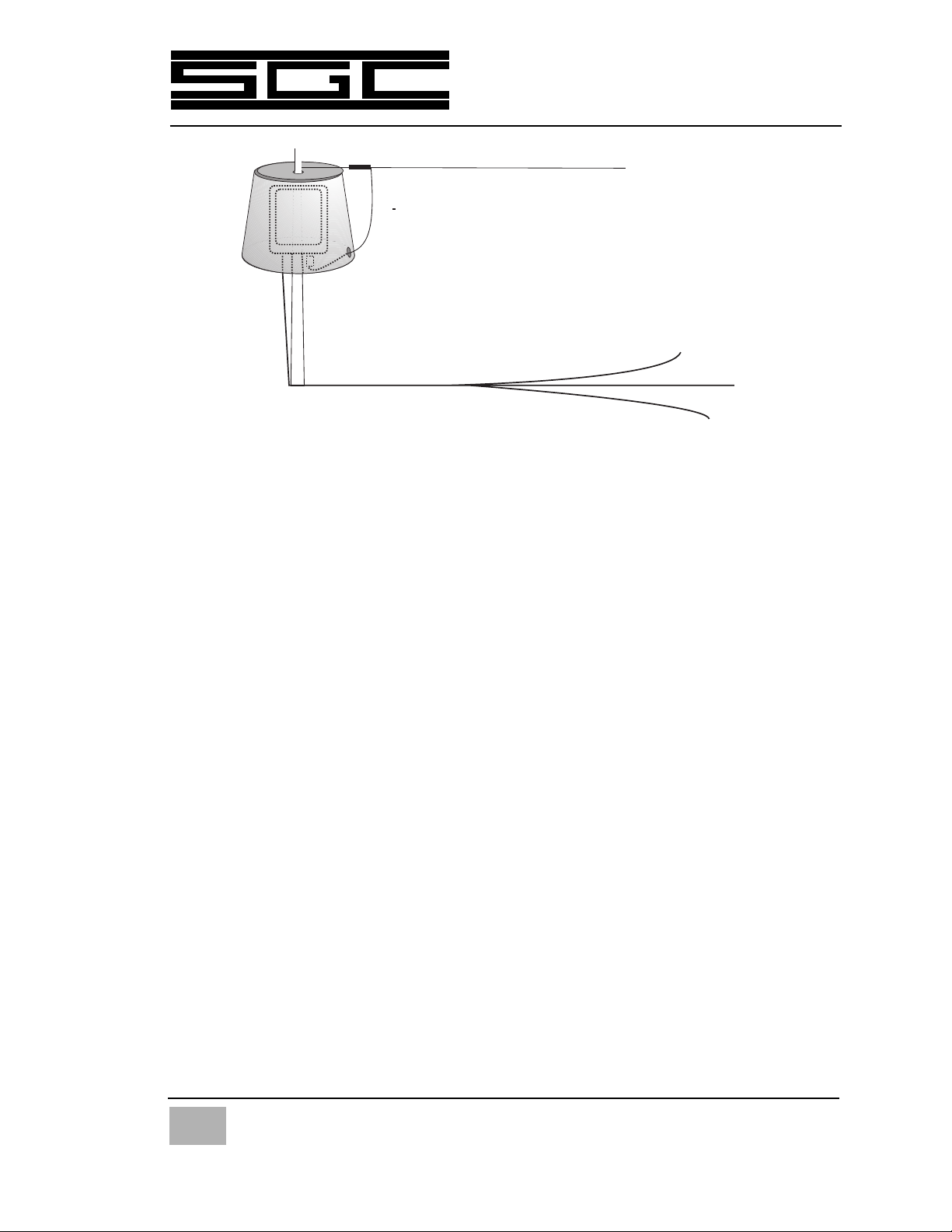
Smartuner mounted inside a plastic waste
basket to protect it from extreme heat and
heavy icing. This type of enclosure is widely
available in all countries.
Long wire antenna

below 10 volts, the coupler will go into a retuning sequence.
For this reason, SGC recommends that if distances are great, the input DC
voltage at the transmitter site be adjusted to provide for 12 to 14 volts at the
coupler site.
We do specifically advise against use of a different power supply than is used
to power the radio because of the danger of creating ground loops which may
cause oscillation of the final amplifiers or other undesired side effects. If you
decide to use a separate power supply mounted at the antenna coupler location,
please be advised that SGC does not provide technical support in this area.
11..1111UUppggrraaddeeSSeeqquueennccee
The current version of the SG-230 coupler will have a revision number or let-
ter located on the printed circuit board. The first Smartuners were lower
numbers or early in the alphabet. More recent version of the coupler are in
the "T" range of the alphabet and beyond.
The Smartuner is one of the most finely tuned products on the market. Each
revision of the coupler includes the newest circuit designs in order to contin-
ue moving the state of the art forward in coupler design.
The original Smartuners with Revision numbers prior to "R" were usually
three wire sets plus coax. In other words, the coupler control line was not
available.
With the advent of Revision R, the reset line was added to allow the operator to
force the unit into the bypass mode on receive (useful for broadband scan-
ning) and to find the lowest possible SWR under a given set of conditions on a
single particular frequency.
Revision T of the coupler was the next major move forward with the addition of
the locking function to keep the coupler from retuning.
SGC will continue making incremental improvements in the Smartuner prod-
uct. When you buy your product today and a new feature is added, you can
always upgrade for modest fees to the latest version of the unit. The versions
change are infrequent now, however, because the unit is so highly refined
and meets the needs of HF professionals.
However, if you ever hear a long time Smartuner user saying they would like
to upgrade to the latest version of the unit, have them contact SGC because spe-
cial discounts are provided to our customers.
15
© 1998 SGC Inc
SG-230 Manual
SGC Inc. SGC Building, 13737 S.E. 26th St. Bellevue, WA 98005 USA
P.O. Box 3526, 98009 Fax: 425-746-6384 Tel: 425- 746-6310 or 1-800-259 7331

16
22..00SSppeecciiffiiccaattiioonnss--SSGG--223300
HF Frequency Range: 1.8 to 30 MHz
Note: The SG-230 may be operated as low as 1.6 MHz
and is commonly used as an antenna matching unit for differential GPS trans-
mitter site antennas. However, when operated under these conditions, a
longer antenna is recommended, such as a 60 foot tower section for operation
in the 1700-1710 KHz band and an appropriately larger counterpoise. In addi-
tion, inductor heating may become pronounced at high power levels in the
SG-230's torroid inductors which are commonly used at these frequencies. For
this reason, we recommend 70 watts at 1700 KHz and 50 watts at 1600 KHz on a
continuous basis.
Power Input Range: 3 to 200 watts (PEP)
Input Impedance Range: 45 to 55 ohms
VSWR: (Typical) Typically less than 2:1
DC Input Requirement: 13.8 VDC
DC Operating Range: 10 to 15 VDC
Input Current: Average: .9 amps
Random set time: Typical: less than 2 seconds
Recurrent set time: Typical: less than 10 milliseconds
Antenna Length: 8 to 80 ft., 3.3-30 MHz
25 to 80 ft., 1.6-30 MHz
Installation: Any position
Operating Temperature: -35¡ to + 70¡C
Size: 16D x 12W x 3H inches 40.6D x 30.5 W x 7.6H
centimeters
Weight: 8 pounds (3.5 kilos)
Case Construction: Plastic ABS weatherproof case
(optional shock mount tray)
Control Cable: SGC special cable, 9 feet coaxial and two power
input wires (replaceable by any standard cable),
RMT tune and Smartlock wire
Catalog Number: 54-12
CATALOG NUMBER: 54-
22..11AAcccceessssoorriieess
Shock Mounting Tray. SGC Part Number 54-50
24 VDC Power option. SGC Part Number 54-52
25 foot extension cable. SGC Part Number 54-61
50 foot extension cable. SGC Part number 54-62
SmartLock control box.. SGC Part Number 54-63
SGC Inc. SGC Building, 13737 S.E. 26th St. Bellevue, WA 98005 USA
P.O. Box 3526, 98009 Fax: 425-746-6384 Tel: 425- 746-6310 or 1-800-259 7331
© 1998 SGC Inc
SG-230 Manual

22..22RReeccoommmmeennddeeddAAnntteennnnaass
SSGG--110033Broadband Base Antenna. 50 ohms - 150
watts (90 feet) SGC Part Number 55-04.
SSGG--110044Broadband Base Station Antenna.
50 ohms - 1kw (90 feet) SGC Part Number 55-06
SSGG--220033Marine 28 foot whip antenna.
This antenna is used for most power boat
installations. SGC Part Number 55-23.
SSGG--330033High performance 9 foot whip antenna.
This dual element antenna is designed for
severe marine and land mobile service.
SGC Part Number 55-27.
SSGG--330077MARINE AND MOBILE ANTENNA - 7 Ft.
Lightweight and low-cost mobile antenna
system for operation between 1 to 60 MHz.
Consisting of adjustable mount and spring.
Antenna must be used with an antenna coupler
such as the SG-231. Radiation is omnidirectional.
Rated for use on vehicles or boats at up to 75mph.
SGC Part Number 55-28.
QQMMSSQuick Mounting System which houses
SG-230 Smartuner and also provides a sturdy
mounting platform for the SG-303 antenna
system. Designed for fly away installations
requiring no holes installation of high
performance HF antenna system.
SGC Part Number 55-45.
33..00PPaarrttssFFuurrnniisshheedd
1. Antenna Coupler
2. 9 foot special cable (RG-58 plus 4 conductors in a single jacket.)
3. Instruction Manual
33..11UUsseerrSSuupppplliieeddIItteemmss
The user of the SG-230 will need to supply a suitable HF radio antenna. Such
an antenna may be as simple as an 8 foot long piece of wire and several
17
© 1998 SGC Inc
SG-230 Manual
SGC Inc. SGC Building, 13737 S.E. 26th St. Bellevue, WA 98005 USA
P.O. Box 3526, 98009 Fax: 425-746-6384 Tel: 425- 746-6310 or 1-800-259 7331

18
ground/counterpoise radials of 8 feet or longer. The longer the antenna,
up to about 80 feet, the better all around performance will be. Longer
antennas may be used, but please refer to the sections on antennas for dis-
cussion of limitations.
The user will also have to supply a good counterpoise. Such a counterpoise
is a large metal surface (much larger electrically than the antenna).
Generally, the bigger the counterpoise, the better your signal will be.
33..22TTeecchhnniiccaallSSuuppppoorrtt
Before contacting SGC for technical support, please take a few minutes to
think through your installation and ask if there is anything obvious which
you have overlooked in the installation. Check to make sure your ground
system is both adequate and tight and that proper voltage is supplied to the
coupler.
In the event you experience difficulty with your SG-230 antenna coupler,
you should contact SGC for technical advise. Before calling, we ask you to
have the following information ready so that we may readily assist you.
CCoouupplleerrIInnffoorrmmaattiioonnPlease have the serial number of your coupler,
the name of the dealer from whom the unit was purchased and the approxi-
mate date of purchase.
AAnntteennnnaaIInnffoorrmmaattiioonnPlease be ready to describe your antenna instal-
lation. You will need to advise us whether the antenna is a wire type, a
dipole, vee, vertical, long wire or whip antenna.
GGrroouunnddSSyysstteemmYou should be ready to describe your ground system in
detail. If you are dealing with a marine installation, you should have a
description of the vessel's bonding system. If you are using the coupler in a
mobile setting, you should be able to describe bonding of the hood, trunk
and other vehicle parts which may have been done. In an aircraft, you
should be able to describe the location of the coupler and the type of ground
connection used.
PPoowweerrssuuppppllyyvvoollttaaggeeOne of the common mistakes made when
installing couplers is to assume that a connection is good when it hasn't
been measured. If you experience any type of erratic or intermittent opera-
tion, please measure the power supply voltage inside the coupler.
DDeessccrriibbeeTTuunneerrbbeehhaavviioorrIf you are having a problem, determine if it
is happening all the time or only part of the time. Does the problem occur
SGC Inc. SGC Building, 13737 S.E. 26th St. Bellevue, WA 98005 USA
P.O. Box 3526, 98009 Fax: 425-746-6384 Tel: 425- 746-6310 or 1-800-259 7331
© 1998 SGC Inc
SG-230 Manual

only on certain frequencies? Does the problem only happen in certain
modes? This type of information is extremely useful in quickly isolating
your problem.
BBeeppaattiieennttFinding the reason for less than ideal system operation may
take one telephone call or it may take several calls. Regardless of how com-
plex the problem is, your SGC representative will be able to walk you
through the process of solving your problem in a logical step-by-step man-
ner. There is nothing magic about HF. Although it may seem so at times, the
rules of physics don't change. The Smartuner and accessories will always
give top performance when carefully installed.
44..00AAnntteennnnaaTTyyppeess
The automatic antenna tuner is designed for use with end-fed unbalanced
antennas such as whips and long wires. The radiating portion of the anten-
na is connected directly to the tuner through a high voltage insulator. It is
extremely important that the antenna type, site location and grounding
technique be correctly chosen so that the system will radiate effectively.
Broadband resonant antennas (e.g. log periodic) that cover the full range of
the system may be used with the tuner if desired. Narrow band resonant
antennas, such as dipoles, vee's and inverted vee's may only be used if the
antenna VSWR (including coaxial feeder) is less than, or equal to 3:1 at the
operating frequency.
Note that if a dipole or Vee type antenna; is used, the antenna may be oper-
ated at any frequency within the range of the coupler if each side of the vee
or dipole is 23 feet or longer. In addition, the SG-230 is just as happy feeding
a conventional Vee antenna as an inverted Vee. The coupler is very flexible
in this regard.
44..11AAnntteennnnaaSSeelleeccttiioonn
The automatic antenna tuner will operate into almost any end fed antenna
with a length of 2.5 meters or more, provided an effective ground is used.
The antenna efficiency will be proportional to length and in most applica-
tions will be maximum at a length of 1/4 wavelength. This means that the
longest possible antenna should be selected for each installation.
Very short antennas are only recommended when there is no other alterna-
tive such as in a vehicular mobile installation. The performance of short
whip antennas is usually very poor, particularly at the lower frequencies,
19
© 1998 SGC Inc
SG-230 Manual
SGC Inc. SGC Building, 13737 S.E. 26th St. Bellevue, WA 98005 USA
P.O. Box 3526, 98009 Fax: 425-746-6384 Tel: 425- 746-6310 or 1-800-259 7331

20
and radiation efficiency will be only a few percent of a full sized antenna.
However, a special electrically long antenna such as the SG-303 9 ft. mobile
antenna overcomes much of the radiation problem.
44..22WWhhiippAAnntteennnnaass--22..55--33..00mmeetteerrss((88--99fftt))
This antenna is recommended only for vehicular mobile installations. The
short length will result in poorer performance when compared with the
longer antennas. A special high performance 9 foot antenna, the SG-303 and
the 7 foot SG-307, is manufactured by SGC specifically for this problem. The
SG-303 is SGC Part Number 55-27.
44..33WWhhiippAAnntteennnnaa--77..00ttoo88..55MMeetteerr((2288fftt))
This antenna is recommended for marine installation on smaller vessels. It
may also be used in base stations if there is no way of using a longer anten-
na. The SG-203 is this type of antenna. Order SGC Part Number 55-23.
44..44LLoonnggwwiirreeAAnntteennnnaa--
2233mmeetteerr((7755fftt))aanndd4466mmeetteerr((115500fftt))
For most applications the longwire antenna will give the best results and is
recommended when practical. The diagrams at the end of this section show
some recommended methods of installation. These are only a few of the
many possible methods of installation and frequently a different configura-
tion will be the best at a particular site. SGC's long wire antenna, 60 feet in
length, provides efficient operation on low frequencies and high frequen-
cies alike. Order SGC Part Number 55-10.
44..55BBaacckkssttaayyAAnntteennnnaass--
88mmeetteerrss((2288fftt))aannddlloonnggeerr
Although we would love to sell everyone a high performance marine whip
antenna, the backstay of a sailboat is almost impossible to improve upon in
most installations.
SGC Inc. SGC Building, 13737 S.E. 26th St. Bellevue, WA 98005 USA
P.O. Box 3526, 98009 Fax: 425-746-6384 Tel: 425- 746-6310 or 1-800-259 7331
© 1998 SGC Inc
SG-230 Manual
Other manuals for Smartuner SG-230
2
Table of contents
Other SGC Adapter manuals


