SGC DF-2 User manual

DF-2
MEDIUM VOLTAGE SWITCHGEAR
THE MODULAR CONCEPT
INSTRUCTION VDS EXCHANGE HR TO LRM D/EDN
READ THIS DOCUMENT CAREFULLY BEFORE ANY OPERATION
THE SPECIALIST IN MEDIUM VOLTAGE SWITCHGEAR
SwitchGear Company nv -Moorstraat 24 -B-9850 Nevele - Belgium

DW604316 (Rev.0 dd.26/04/2016) Page 2/11
© 2016 SGC - SwitchGear Company n.v.
All rights reserved.
The information provided herein may not be reproduced and/or (re)published in any way and by any means
(electronic or mechanical), without the prior, explicit written authorization of SGC nv - SwitchGear Company.
The information provided herein is based on general data concerning the construction, known at the time of
publication, and concerning the qualities of the material and working methods. Consequently, the right to make
changes is reserved.
The information contained within is applicable to the standard version of the DR-6 medium-voltage switchgear.
Therefore, SGC nv - SwitchGear Company cannot be held liable for any damage resulting from specifications that
differ from the standard version of the DR-6 medium-voltage switchgear.
The available information has been assembled with the greatest possible care, but SGC nv - SwitchGear
Company cannot be held liable for any mistakes in the information, or the consequences thereof.
The user names, trade names, trademarks, etc., used by SGC nv - SwitchGear Company cannot, in accordance
with the legislation concerning the protection of trademarks, considered to be free.

DW604316 (Rev.0 dd.26/04/2016) Page 3/11
TABLE OF CONTENTS
TABLE OF CONTENTS 3
PREFACE 4
INTRODUCTION 4
PICTOGRAMS AND SAFETY SYMBOLS IN AND ON THE MEDIUM VOLTAGE SWITCHGEAR 4
PICTOGRAMS IN THE DOCUMENTATION 5
RELATED DOCUMENTATION 5
SERVICE AND TECHNICAL SUPPORT 6
GENERAL SAFETY DIRECTIONS AND INSTRUCTIONS6
INTENDED USE 7
1CONTENT OF LRM KIT (D/EDN CUBICLE) 8
2VDS EXCHANGE ON A/D-EDN CUBICLE 8
2.1 DISASSEMBLY OF THE HR FRONTPLATE 9
2.2 MOUNTING OF THE LRM FRONTPLATE 10
2.3 INSTALLATION OF THE VOLTAGE INDICATOR 10
2.3.1 VERIFICATION OF THE C2 VALUE 10
2.3.1.1 Voltage range 5-11kV 10
2.3.1.2 Voltage range 10-24kV 10
2.3.2 CONNECTION BETWEEN CAPACITIVE INSULATORS AND VDS 11
3VERIFICATION OF THE PROPER FUNCTIONING 11

DW604316 (Rev.0 dd.26/04/2016) Page 4/11
PREFACE
Introduction
This document is intended as a reference for qualified and trained operators to install
the medium voltage switchgear in a safe and economical way.
This document uses the term “medium voltage switchgear” to denote a random, but
in actual practice, existing combination of DR6 functions that, mutually coupled and
connected, constitute a client-specific transformation or distribution station.
In the documentation the words “left”, “right”, “front” and “behind” are used to indicate
a specific part of the medium voltage switchgear. The starting point is always the
position of the operator, standing in front of the medium voltage switchgear, facing
the switchgear.
Pictograms and safety symbols in and on the medium voltage
switchgear
Depending on the version, the following pictograms are used on the medium voltage
switchgear:
WARNING
Danger of high voltage
Access to this cubicle is only allowed after this cubicle and both the
directly adjacent cubicles (previous and next one) are de-energized.
WARNING
Drilling prohibited.
Drilling is strictly prohibited on surfaces equipped with this pictogram.

DW604316 (Rev.0 dd.26/04/2016) Page 5/11
Pictograms in the documentation
The following pictograms apply to the medium voltage switchgear user documents:
CAUTION!
A procedure that can, if not carried out with the proper care, result in
damage to the medium voltage switchgear, the surrounding area or the
environment.
WARNING
High Voltage Danger
CAUTION!
Clamping danger
Notes, suggestions and advice.
Make this cubicle, the next one and the previous cubicle, voltage-free,
before carrying out the work described.
Open the load break switch and the earthing switch before carrying out the
work described in the manual.
Make this cubicle, the next one and the previous cubicle, voltage-free,
before carrying out the work described. Open the load-break switch and
the circuit breaker. Close the earthing switch
Consult the indicated information sources first.
Protect the medium voltage switchgear from water and damp.
Related documentation
The following technical documentation for medium voltage switchgear is available:
•Installation manual DF-2
•User manual DF-2

DW604316 (Rev.0 dd.26/04/2016) Page 6/11
Service and technical support
For information concerning specific settings, maintenance or repair work which is not
covered in the manual, please contact SGC - SwitchGear Company nv.
When contacting SGC – Switchgear Company nv, always provide the following
information:
−Cubicle designation and characteristics
−Serial number of the cubicle(s)
General safety directions and instructions
SGC – SwitchGear Company nv does not accept any liability for damage or injury
caused by not (strictly) following the safety directions and instructions, or by
negligence during the installation, use, maintenance, or the repair of the medium
voltage switchgear and its accompanying options.
Depending on specific user circumstances, or installed options, extra safety
instructions may be required. Please contact SGC – SwitchGear Company nv
immediately if you encounter a potential danger during the operation of the medium
voltage switchgear.
The owner/operator of the medium voltage switchgear is fully responsible at all
times for following the locally applicable safety directions and guidelines.
User manual
•Anyone who uses or operates the medium voltage switchgear, must be
familiar with the contents of the user manual, and follow the directions
contained within very closely. The owner/operator must educate the users in
accordance with the user manual and obey all directions and instructions.
•Never change the order of the required actions.
•Always keep the user manual in the vicinity of the medium voltage switchgear.
Pictograms and safety symbols
The pictograms, symbols and instructions applied to the medium voltage switchgear
are a part of the safety equipment. They may therefore not be covered or removed,
and must be present and clearly readable throughout the entire lifespan of the
medium voltage switchgear.
•Replace or repair unreadable or damaged pictograms, symbols and instruction
immediately. Therefore, contact SGC – SwitchGear Company nv.
Operators
The execution of the work described (transport, installation, use and maintenance) is
strictly reserved for trained and qualified operators, who are familiar with the dangers
that can occur when operating medium voltage switchgear. Temporary staff and
personnel in training may not operate the medium voltage switchgear under any
circumstances.

DW604316 (Rev.0 dd.26/04/2016) Page 7/11
Technical specifications
•Technical specifications may not be changed.
•Modification of the medium voltage switchgear (or parts thereof) is not
permitted.
Transport, storage, installation, operation and maintenance
See corresponding documents:
•“Safety guidelines – transport”
•“Safety guidelines – storage”
•“Safety guidelines – installation”
•“Safety guidelines – operation”
•“Safety guidelines – maintenance”
Cubicles that fell over or have otherwise been damaged always HAVE TO BE
RETURNED to SGC - SwitchGear Company for a checkup
Intended use
The medium voltage switchgear is designed exclusively for use as transformation or
distribution stations, in accordance to the specifications and conditions provided by
SGC – SwitchGear Company nv. Any other or further use is not in accordance with
the intended use.1
SGC – SwitchGear Company nv does not accept any liability for damage(s) or
injuries resulting from deviation(s) of the intended use.
The medium voltage switchgear complies with the current norms and guidelines.
See: Technical Brochure
•Only use the medium voltage switchgear in technically perfect condition, in
accordance with the intended use described above.
Leave the sealed connections intact, at all times. Breaking the sealed
connections irrevocably voids any guarantee claims.
1The “Intended use” as defined in EN 292-1 “is the use for which the technical product is suited as
specified by the manufacturer including his directions in the sales brochure.” In case of doubt, it is the
use that can be deduced from the construction, the model and the function of the technical product
that is considered normal use. Operating the product within the limits of its intended use also involves
observing the instructions in the user manual.

DW604316 (Rev.0 dd.26/04/2016) Page 8/11
1 CONTENT OF LRM KIT (D/EDN CUBICLE)
The delivered kit contains:
•Pre-assembly frontplate DA-EDN suited for LRM
•Voltage indicator of the type LRM
The required type of VDS should be specified during the order
2 VDS EXCHANGE ON A/D-EDN CUBICLE
This exchange may be performed at an installation in service. Therefore it is
required to earth the three conductors prior to disconnect them from the
voltage indicator. A special kit can be provided optionally (Figure 1).
Figure 1: Earthing of the voltage indicator

DW604316 (Rev.0 dd.26/04/2016) Page 9/11
2.1 Disassembly of the HR frontplate
Open the LV compartment of relevant cubicle. The HR frontplate of the mechanism
can be removed after disassembly of the 4 nuts (Figure 2- A). The HR frontplate
(Figure 3-A) can now be removed as given in Figure 3.
Figure 2: Rear view DA-98 EDND
mechanism
Figure 3: Remove HR frontplate
Unplug the three connectors and the earthing connection at the rear side of the HR-2
interface.
Figure 4: Disconnect the HR-2 interface

DW604316 (Rev.0 dd.26/04/2016) Page 10/11
2.2 Mounting of the LRM frontplate
Mount the pre-assembly of the LRM-frontplate on the mechanism (Figure 5-A). Fix
the LRM-frontplate by means of the 3 nuts (Figure 5-B).
Figure 5: Mounting of the LRM frontplate
2.3 Installation of the voltage indicator
2.3.1 Verification of the C2 value
The verification of the C2 value is only applicable on the voltage indicator type
Capdis S1+ and Capdis S2+. The C2m module can be found at the back side of the
voltage indicator. Set the desired C2 value were the red mark is indicated.
2.3.1.1 Voltage range 5-11kV
C2 value should be set on 33nF
2.3.1.2 Voltage range 10-24kV
C2 value should be set on 69nF
Figure 6: Voltage indicator type Capdis

DW604316 (Rev.0 dd.26/04/2016) Page 11/11
2.3.2 Connection between capacitive insulators and VDS
The different conductors coming from the capacitive insulators are labelled in
accordance with the corresponding phase. On the back side of the voltage indicator,
the corresponding phase is given next to the connector.
Next to the three phases, the ground terminal should be connected.
Figure 7: Connection on the back side of the VDS
After the connection of the conductors to the voltage indicator, the earthing
connection of the conductors can be removed (if present, see §2)
Once the connection between the voltage indicator and the capacitive insulators are
made, the voltage indicator mounted in the LRM frontplate by pressing the VDS into
the opening.
3 VERIFICATION OF THE PROPER FUNCTIONING
It is recommended to verify the proper functioning of the installed voltage indicator by
performing a verification of the phase sequence by applying a test voltage to each
individual phase. During this test one should check the proper functioning “voltage
present” of the installed voltage indicator.
If the installation is in service during the exchange of the voltage indicators, the
phase sequence can be verified by removing the earth connection (if present, see
§2) one phase at a time.
Other manuals for DF-2
2
Table of contents
Popular Industrial Electrical manuals by other brands
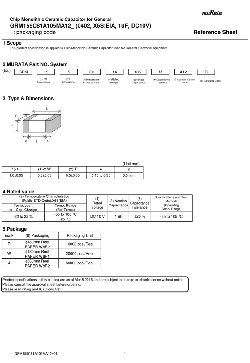
Murata
Murata GRM155C81A105MA12 Series Reference sheet
VARISCO
VARISCO JE Series Instructions for the use and maintenance
Murata
Murata GRM219C80J106ME39 Series Reference sheet

Murata
Murata GRM219R71C224KA01 Series Reference sheet
Wiremold
Wiremold Legrand Omnibox installation instructions
Siemens
Siemens SIVACON 8PS installation instructions
