ELTEX R23ATR Series User manual

Operating Instructions
R23ATR point charging bar
BA-en-3021-1912
F01029y

2BA-en-3021-1912_R23ATR

BA-en-3021-1912_R23ATR 3
List of Contents
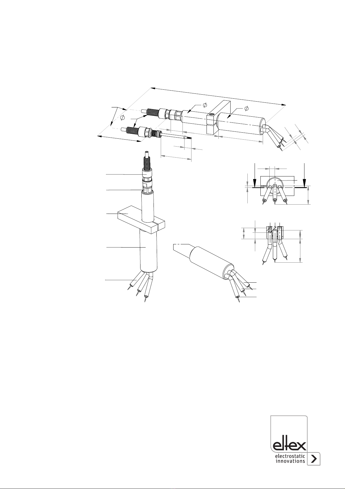
1 Overview and dimensions . . . . . . . . . . . . . . . . . . . . . . . . . . . . . . 5
1.1 Overview point charging bar R23ATR/L. . . . . . . . . . . . . . . . . . . . . . 5
1.2 Overview point charging bar R23ATR/R . . . . . . . . . . . . . . . . . . . . . 6
1.3 Overview point charging bar R23ATR11 . . . . . . . . . . . . . . . . . . . . . 7
1.4 Design options of the point charging bar . . . . . . . . . . . . . . . . . . . . . 8
1.4.1 Design options of the point charging bar R23ATR . . . . . . . . . . . . . . 8
1.4.2 Design options of the point charging bar R23ATR11 . . . . . . . . . . . . 9
2 Safety . . . . . . . . . . . . . . . . . . . . . . . . . . . . . . . . . . . . . . . . . . . . . . 10
2.1 Identification of risks and hazards . . . . . . . . . . . . . . . . . . . . . . . . . 10
2.2 Proper use . . . . . . . . . . . . . . . . . . . . . . . . . . . . . . . . . . . . . . . . . . . 10
2.3 Work and operational safety . . . . . . . . . . . . . . . . . . . . . . . . . . . . . 11
2.4 Contact protection . . . . . . . . . . . . . . . . . . . . . . . . . . . . . . . . . . . . . 13
2.5 Inspection of the protective resistors contact protection. . . . . . . . . 13
2.6 Technical advance . . . . . . . . . . . . . . . . . . . . . . . . . . . . . . . . . . . . . 13
3 Installation and assembly . . . . . . . . . . . . . . . . . . . . . . . . . . . . . . 14
3.1 Installation of the point charging bar . . . . . . . . . . . . . . . . . . . . . . . 14
3.2 Distance of the emission tips from the material web . . . . . . . . . . . 15
3.3 High voltage cable of the charging bar . . . . . . . . . . . . . . . . . . . . . 16
3.3.1 Version with fixed cable connection . . . . . . . . . . . . . . . . . . . . . . . . 16
3.3.2 Version with detachable cable connection . . . . . . . . . . . . . . . . . . . 16
3.4 Connecting the high voltage cable of the charging bar to the
high voltage generator KNH34 / KNH64, KNH35 / KNH65 . . . . . . 17
3.5 Connecting the high voltage cable of the charging bar to the
high voltage generator POWER CHARGER PCSC . . . . . . . . . . . . 18
3.6 Disconnecting the high voltage cable . . . . . . . . . . . . . . . . . . . . . . 19
4 Operation . . . . . . . . . . . . . . . . . . . . . . . . . . . . . . . . . . . . . . . . . . . 20
4.1 Setting the operating voltage . . . . . . . . . . . . . . . . . . . . . . . . . . . . . 20
5 Maintenance . . . . . . . . . . . . . . . . . . . . . . . . . . . . . . . . . . . . . . . . . 21
6 Warranty . . . . . . . . . . . . . . . . . . . . . . . . . . . . . . . . . . . . . . . . . . . . 22
7 Troubleshooting . . . . . . . . . . . . . . . . . . . . . . . . . . . . . . . . . . . . . 23
8 Technical specifications . . . . . . . . . . . . . . . . . . . . . . . . . . . . . . . 24
9 Spare parts and accessories . . . . . . . . . . . . . . . . . . . . . . . . . . . 25
Declaration of Conformity . . . . . . . . . . . . . . . . . . . . . . . . . . . . . . . . . . 27

4BA-en-3021-1912_R23ATR
Dear customer
The R23ATR point charging bar is a robust bar for the point or edge charg-
ing of non-conductive surfaces. The charging bar is used wherever static
electrical charges may be used beneficially in production processes, e.g.
in edge fixation during film production.
The point charging bar is mounted directly behind the flat film of the
extruder. The charging bars are used to charge both film edges and to fix
the edges to the chill roll. This arrangement prevents neck-in.
The R23ATR/__ point charging bar operates with a maximum high voltage
of 30 kV DC, depending on the design the R23ATR11operates with a
maximum high voltage of 60 kV DC; it is also suitable for use in higher
ambient temperatures.
The advantage of the point charging bar is that it can be operated with
either one, two or three exchangeable emission tips. The geometry of the
emission tips is freely selectable, offering the best possible adaption to
your production processes. The bars can be operated horizontally, verti-
cally and in very confined spaces.
Please read these instructions carefully before starting the unit. This will
help you prevent personal injuries and damage to property.
Simply give us a call if you have any suggestions, proposals or ideas for
improvements. We greatly appreciate the feedback from the users of our
appliances.

BA-en-3021-1912_R23ATR 5
1. Overview and dimensions
1.1 Overview point charging bar R23ATR/L
1 Emission tips
2 Base element PU
3 GRP holder for installation (provided by the customer)
4 Cable gland
5 Detachable high voltage cable for connecting to the
high voltage generator (accessories: not supplied)
6 Hole diagram and mounting depth of the emission tips
Fig. 1:
R23ATR/LAAA
point charging bar
design left with
emission tip
Type A
Z-116463_1y
!
PLQ
5
$$

6BA-en-3021-1912_R23ATR
1.2 Overview point charging bar R23ATR/R
1 Emission tips
2 Base element PU
3 GRP holder for installation (provided by the customer)
4 Cable gland
5 Detachable high voltage cable for connecting to the
high voltage generator (accessories: not supplied)
6 Hole diagram and mounting depth of the emission tips
Fig. 2:
R23ATR/RAAA
point charging bar
design right with
emission tip
Type A
Z-116463_2y
!
PLQ
5
$$

BA-en-3021-1912_R23ATR 7
1.3 Overview point charging bar R23ATR11
1 Emission tip
2 Base element PU
3 Cable gland
4 Detachable high voltage cable for connecting to the
high voltage generator (accessories: not supplied)
1 Emission tip
2 Base element PU
3 Cable gland
4 Detachable high voltage cable for connecting to the
high voltage generator
Fig. 3:
Point charging bar
with detachable
high voltage cable
designed: Type
R23ATR11/_A
with emission tip
Type A
Z-116539ay_2
o
NJO
3
Fig. 4:
Point charging bar
with fixed high
voltage cable
designed: Type
R23ATR11/_AY
with emission tip
Type A
Z-116539ay_1
o
NJO
3

8BA-en-3021-1912_R23ATR
1.4 Design options of the point charging bars
1.4.1 Point charging bar R23ATR
1.1 1. emission tip
1.2 2. emission tip
1.3 3. emission tip
Overview of the emission tips: please see table chapter 9
Fig. 5:
R23ATR
point charging bar
Design
L = left (standard)
R = right
1. Emission tip
2. Emission tip
3. Emission tip
Plug version
n.n. = detachable version
Y = connection POWER CHARGER
PCSC
Cable length in dm (decimeter)
5 dm steps
n.n. = detachable version
5$75>@>@>@>@>@>@>@>@
Fig. 6:
R23ATR
point charging bar
design
left and right
09308X4gy_3+4
design left
R23ATR/LAAA
design right
R23ATR/RAAA

BA-en-3021-1912_R23ATR 9
1.4.2 Punktaufladeelektrode R23ATR11
1 Protecting tube
2 Terminal adapter
3 Cable gland: black at R23ATR and R23ATR11/3
yellow at R23ATR11/6
4 Interlock
5 Bar element
Overview of the emission tips: please see table chapter 9
Fig. 7:
R23ATR11
point charging bar
Design
3 = 30 kV
6 = 60 kV
Emission tip
Plug version
n.n. = detachable version
Y = connection POWER CHARGER
PCSC
Cable length in dm (decimeter)
5 dm steps
n.n. = detachable version
09308X4gy_2
5$75>@>@>@>@>@>@
Fig. 8:
R23ATR11
point charging bar
with fixed high
voltage cable
Z-116539ay_3
Fig. 9:
R23ATR11
point charging bar
with detachable
high voltage cable
Z-116539ay_4

10 BA-en-3021-1912_R23ATR
2. Safety
The units have been designed, built and tested using state-of-the-art engi-
neering, and have left the factory in a technically and operationally safe
condition. If used improperly, the units may nevertheless be hazardous to
personnel and may cause injury or damage. Read the operating instruc-
tions carefully and observe the safety instructions.
2.1 Identification of risks and hazards
Possible risks and hazards resulting from the use of the units are referred
to in these operating instructions by the following symbols:
Warning!
This symbol appearing in the operating instructions refers to operations
which, if carried out improperly, may result in serious personal injuries.
Caution!
This symbol appearing in the operating instructions refers to operations
which, if carried out improperly, may result in damage to property.
2.2 Proper Use
The R23ATR point charging bar must only be used for applying static elec-
trical charges onto paper, fabrics, films and other non-conductive materi-
als for the purpose of improving and accelerating production processes.
The R23ATR point charging bar may only be operated with the Eltex high
voltage generators up to maximum 30 kV DC, the R23ATR11 up to maxi-
mum 60 kV DC depending on the design.
The Eltex high voltage generator POWER CHARGER PCSC can be used
together with versions with fixed high voltage cables.
The manufacturers will not assume any liability and warranty if the units
are used improperly or used outside the intended purpose.
Modifications or changes made to the devices are not permitted.
Use only original Eltex spare parts and equipment.

BA-en-3021-1912_R23ATR 11
2.3 Work and operational safety
Warning!
Electric shock hazard!
Carefully observe the following notes and the complete chapter 2 "Safety”,
page 10!
• Before carrying out repairs, cleaning or maintenance work and before
resetting after malfunctions, switch off the power supply and disconnect
the mains supply voltage (see chapter 5 "Maintenance”, page 21, chap-
ter 7 "Troubleshooting”, page 23)
• Before carrying out any work involving the units, the machine which has
the units fitted must not be in operation (see chapter 5 "Maintenance”,
page 21, chapter 7 "Troubleshooting”, page 23).
• Any work involving the units must be carried out by qualified electri-
cians (see chapter 5 "Maintenance”, page 21, chapter 7 "Troubleshoot-
ing”, page 23).
• The bars passively absorb energy from the moving substrate web. The
high voltage cable must be plugged in or grounded to the power supply.
If the high voltage cable is disconnected, the plug is live (high voltage)
and applies with full power on the plug; this may cause a spark dis-
charge and may lead to a risk of injury. Disconnected high voltage plugs
are not permitted or have to be grounded (see chapter 5 "Mainte-
nance”, page 21).
• Use only non-conductive material (e.g. GRP) for the installation (see
chapter 3.1 "Installation of the point charging bar”, page 14).
• If personnel are working near the charging bar, the bar must be
screened against inadvertent contact with a mechanical protection
device.
The protective screen must be mounted at a minimum distance of 60
mm from the charging bar and the emission tips.
The protective screen must be made of GRP or similar suitable insulat-
ing material. Protective screens made of conductive material must be
grounded (see chapter 3.1 "Installation of the point charging bar”,
page 14).
• Before adjusting the bar with the operating voltage applied, make sure
that the bar is clean and dry and that the cable and the bar are un-
damaged. Moisture, dirt and defective parts carry the risk of electric
shock. When adjusting the bar with the operating voltage applied, the
operator must wear conductive footwear (see chapter 3.2 "Distance of
the emission tips from the material web”, page 15).
• Make sure that the units are clean at all times.
Dirt results in malfunctions and in premature wear of the units.

12 BA-en-3021-1912_R23ATR
• The high voltage cable is connected to the bar via a plug. Work on the
male connector must be carried out under offload conditions (see chap-
ter 3.3.2 "Version with detachable cable connection”, page 16).
• The high voltage cable must be pushed up to the stop (90 mm for
KNH34/KNH35 and 120 mm for KNH64/KNH65) into the cable inlet!
The connec-ting area of the high voltage cable must be kept clean (see
chapter 3.4 "Connecting the high voltage cable of the charging bar to
the high voltage generators KNH34 / KNH64, KNH35 / KNH65”,
page 17).
• The high voltage cable must be pushed up to the stop (150 mm) into
the cable inlet! The connecting area of the high voltage cable must be
kept clean (see chapter 3.5 "Connecting the high voltage cable of the
charging bar to the high voltage generator POWER CHARGER PCSC”,
page 18).
• Uncontrolled sparking on the charging bar must be avoided.
Reduce the high voltage or increase the distance from the substrate
(see chapter 5 "Maintenance”, page 21).
• When cleaning the bars do not soak the bars and the high voltage cable
in solvent and do not damage the emission tips; allow the solvent to
evaporate completely before restarting the unit. No continuous sparking
(electric arc) must be visible on the bar tips (see chapter 5 "Mainte-
nance”, page 21).
• Check the units and the high voltage cables at regular intervals and
before startup for any damage. Any damaged components must be
repaired or replaced professionally before continuing to operate the
unit, or the units must be disabled.
• Do not touch the emission tips - risk of injury.
If the high voltage supply is connected, reflex responses to electrical
irritation can lead to secondary accidents; the charging bar as such is
safe to touch. If contact is made, the energy transferred is so low
(≤20 tips) that there is no risk of injury.
• Potential dangers for persons with cardiac pacemakers
The contact of several emission tips with the hand can trigger or sup-
press a single impulse. Such a single influence is irrelevant. A repeated
contact during a short period can be excluded because the electrical
irritation causes a warning effect. The charging bar as such is safe to
touch. If contact is made, the energy transferred is so low that there is
no risk of injury.
• The operation of the bars can generate ozone. The ozone concentra-
tion levels developing near the bars depend on many different factors
such as site of installation, bar current and voltage, air circulation, etc.,
and can therefore not be specified in general terms.
If the maximum allowable concentration of ozone must be observed at

BA-en-3021-1912_R23ATR 13
the site of installation of the bar, the concentration must be measured
on site.
The AGW value (maximum admissible concentration) serves to assess
the ozone concentration at the workplace. The user must make sure
that the appropriate national AGW value is at no times exceeded, e.g.
in Germany the ozone concentration occurring during the operation of
the system must not exceed the recommended value based on interna-
tional limits of 0.06 ml/m³ (0.12 mg/m³).
• Static on personnel
Static charges on personnel are unlikely if the bars are installed pro-
perly. Personnel must wear conductive footwear.
Please note all national regulations regarding electrostatic charge (e.g.
TRGS 727 in Germany).
2.4 Contact protection
The site of installation and/or use of the units is outside the control of
Eltex, contact protection against inadvertent contact of the bars and of live
components by personnel as specified by the employer’s liability insu-
rance association may have to be provided (e.g. DGUV V3 in Germany).
Contact protection devices made of conductive material must be
grounded.
2.5 Inspection of the protective resistors - contact protection
The function and the appearance of the protective resistors must be
inspected at regular intervals. The inspection intervals are specified in the
accident prevention regulations, as amended (e.g. in Germany DGUV
V3). Eltex recommend inspection intervals of 6 months.
The function of the series resistors must be checked using a suitable
measuring device. The test voltage must be 1,000V. The measured resis-
tance between the high-voltage connection and the individual emission tip
must not fall below 234 MOhm and not exceed 286 MOhm.
2.6 Technical advance
The manufacturer reserves the right to make changes to the technical
specifications without prior notice in order to adapt the units to state-of-
the-art engineering. Eltex will provide the latest information on any
changes or modifications in the operating instructions on request.

14 BA-en-3021-1912_R23ATR
3. Installation and assembly
3.1 Installation of the point charging bar
Attach the charging bar to the machine via a holder made of non conduc-
tive material. The Fig. 10 shows a possible assembly configuration. The
charging bar may be installed either horizontally or vertically. Use only
non-conductive material (e.g. GRP) for the installation.
Warning!
Electric shock hazard!
If personnel are working near the charging bar, the bar must be screened
against inadvertent contact with a mechanical protection device.
The protective screen must be mounted at a minimum distance of 60 mm
from the charging bar and the emission tips.
The protective screen must be made of GRP or similar suitable insulating
material. Protective screens made of conductive material must be
grounded.
Fig. 10:
Installation
1Film
2 Holder GRP
3 High voltage cable
4 Flat film die
a Distance of the tip from
the substrate surface
Z00505y
4
R23ATR
3
2
1a

BA-en-3021-1912_R23ATR 15
3.2 Distance of the emission tips from the material web
The optimum distance a to the substrate is 20...40 mm with an operating
voltage of 15...25 kV. In edge tacking to prevent neck-in, a distance of
10 mm with a maximum operating voltage of 20 kV is also permitted (see
Fig. 10).
Warning!
Before adjusting the bar with the operating voltage applied, make sure
that the bar is clean and dry and that the cable and the bar are un-
damaged. Moisture, dirt and defective parts carry the risk of electric
shock. When adjusting the bar with the operating voltage applied, the
operator must wear conductive footwear.

16 BA-en-3021-1912_R23ATR
3.3 High voltage cable of the charging bar
3.3.1 Version with fixed high voltage cable
Using the type R23ATR and type R23ATR11 point charging bar in connec-
tion with the charging generator POWER CHARGER PCSC, only the ver-
sion with a fixed high voltage cable is permitted.
3.3.2 Version with detachable cable connection
The high voltage cable is connected to the bar via a plug. Work on the
male connector must be carried out under offload conditions.
Caution!
Use a screwdriver to open the interlock (4) of the cable gland as shown in
Fig. 11. Pull the high voltage cable with corrugated tube (1) and terminal
adapter (2) out of the bar element (5). Insert the new high voltage cable
with corrugated tube and terminal adapter (2) into the bar element up to
the stop (laminated contact must engage properly). Re-attach the termi-
nal adapter (2) to the interlock (4).
1 Protecting tube
2 Terminal adapter
3 Cable gland: black at R23ATR and R23ATR11/3
yellow at R23ATR11/6
4 Interlock
5 Bar element
Fig. 11:
R23ATR
male connector of
the high voltage
cable
* R23ATR11: Ø20
Z-116463_3y

BA-en-3021-1912_R23ATR 17
3.4 Connecting the high voltage cable of the charging bar to the
high voltage generators KNH34 / KNH64, KNH35 / KNH65
Warning!
Electric shock hazard!
Work may be carried out only if:
• the supply voltage to the generator has been disconnected,
• the machine is at a standstill because the bars pick up charges if the
material web is running.
Method:
Connect the bars via the prefabricated high voltage cable. Push the high
voltage cables up to the stop into the socket connection. Finally, secure
the adapter inside the socket with the clip provided (see figure).
Cables without adapters have a color-coded marking on the flexible
tubing. This marking must lie flush with the outside edge of the coupling.
Note: The clip must be fully inserted.
Caution!
The high voltage cable must be pushed up to the stop (90 mm for KNH34/
KNH35 and 120 mm for KNH64/KNH65) into the cable inlet! The connec-
ting area of the high voltage cable must be kept clean!
Fig. 12:
Connecting the
high voltage cable
Z00178y
Fig. 13:
Inserting the clip correct incorrect
Z00018y

18 BA-en-3021-1912_R23ATR
3.5 Connecting the high voltage cable of the charging bar to the
high voltage generator POWER CHARGER PCSC
Warning!
Electric shock hazard!
Work may be carried out only if:
• the supply voltage to the generator has been disconnected,
• the machine is at a standstill because the bars pick up charges if the
material web is running.
Method:
Connect the bars via the prefabricated high voltage cable. Push the high
voltage cables up to the stop into the socket connection. Finally, the crew
connection is tightened.
9 / 9.1 High voltage outputs 10 High voltage cable
Note:
The screw connection must be fastened with a torque of 3 Nm.
Caution!
The high voltage cable must be pushed up to the stop (150 mm) into the
cable inlet! The connecting area of the high voltage cable must be kept
clean!
Fig. 14:
Connecting the
high voltage cable
Z-116035ay_4

BA-en-3021-1912_R23ATR 19
3.6 Disconnecting the high voltage cable
Warning!
Electric shock hazard!
Work may be carried out only if:
• the supply voltage to the generator has been disconnected,
• the machine is at a standstill because the bars pick up charges if the
material web is running.
Take off the clip at the KNH_ _ generators, using a 3 mm screw driver.
Then pull out the cable.
Disconnect the union nut (SW18) at the POWER CHARGER PCSC
generators. Then pull out the cable.

20 BA-en-3021-1912_R23ATR
4. Operation
4.1 Setting the operating voltage
The operating voltage on the high voltage generator is set at between
15 and 25 kV depending on the distance "a" of the emission tips from the
substrate.
The correct operating voltage is set as soon as the desired effect is
achieved by using the charging bar.
Caution!
Uncontrolled sparking on the charging bar must be avoided.
Reduce the high voltage or increase the distance from the substrate.
This manual suits for next models
3
Table of contents
Popular Industrial Electrical manuals by other brands

Eaton
Eaton HALO E7 ICAT New Construction Series instructions

Murata
Murata GRM0225C1E6R5DA03 Series Reference sheet

Murata
Murata GRM1555C1H180FA01 Series Reference sheet

OEZ
OEZ SJB-50E-1N-MZS Instructions for use

Murata
Murata GRM022R60J104ME15 Series Reference sheet

Murata
Murata GRM0225C1ER70WA03 Series Reference sheet

Murata
Murata GRM155R71H222KA01 Series Reference sheet

Siemens
Siemens 8MF1000-2HA operating instructions

Murata
Murata GRM1555C1H5R6DA01 Series Reference sheet

Murata
Murata GRM155R60J104KA01 Series Reference sheet

Rockwell Automation
Rockwell Automation Allen-Bradley 100-C60 quick start guide

Siemens
Siemens MBC Series installation instructions