SGM LEKTRA VLW602 Guide
VLW602
Display and configuration unit
technical documentation EN Rev. Of 19/07/2022

Page 2 of 32 www.sgm-lektra.com
VLW602 - contents
CONTENTS
1-WARRANTY
2-PRODUCT
3-PERFORMANCE SPECIFICATIONS
4-DIMENSIONS
5-ELECTRICAL CONNECTIONS
6-CONFIGURATION AND CALIBRATION
7-QUICK SETUP
8-ADVANCED SETUP
9-FACTORY TEST AND QUALITY CERTIFICATE
page 3
page 4
page 5
page 6
page 7
page 9
page 10
page 16
page 32

Page 3 of 32
www.sgm-lektra.eu
VLW602 - warranty
Products supplied by SGM LEKTRA are guaranteed for a period of 12 (twelve) months from delivery date
according to the conditions specified in our sale conditions document.
SGM LEKTRA can choose to repair or replace the Product.
If the Product is repaired it will maintain the original term of guarantee, whereas if the Product is replaced it will have 12
(twelve) months of guarantee.
The warranty will be null if the Client modifies, repair or uses the Products for other purposes than the normal conditions
foreseen by instructions or Contract.
In no circumstances shall SGM LEKTRA be liable for direct, indirect or consequential or other loss or damage whether
caused by negligence on the part of the company or its employees or otherwise howsoever arising out of defective goods
1-WARRANTY

Page 4 of 32 www.sgm-lektra.com
VLW602 - product
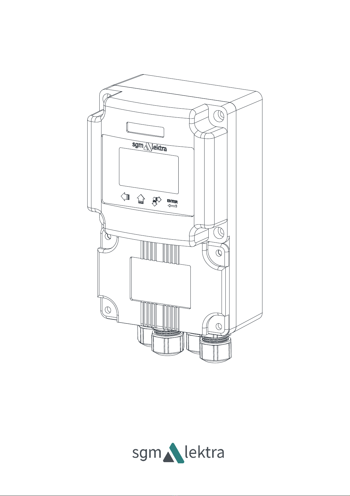
2- PRODUCT
1. DISPLAY
2. CONFIGURATION KEYS
3. REMOVABLE CLAMPING PANEL
4. FOUR PG9 CABLE GLANDS
2.1 IDENTIFICATION
Each meter has an adhesive identification plate on which are the meter main data.
The following picture describes the information and data on the identification plate.
VLW602A0A
PAI091800107
24Vac 50÷60Hz
1. Product code
2. Power supply
3. Serial number
1
2
3
4

Page 5 of 32
www.sgm-lektra.eu
3-FEATURES
Housing material
Epoxy coated aluminum
Mechanical installation
Wall mountig
Protection degree
IP66
Keyboard
4 push buttons
Display
LCD
Electrical connection
Internal connector
Working temperature
-25° ÷ +70°C
Power supply
12÷30 Vdc
85÷265 Vdc
Power consumption
Max. 5W
Power supply for PTU5_
24Vdc
Data comunication with PTU5_
Via MODBUS RTU
VLW602 - features
Page 6 of 32 www.sgm-lektra.com
VLW602 - dimensions
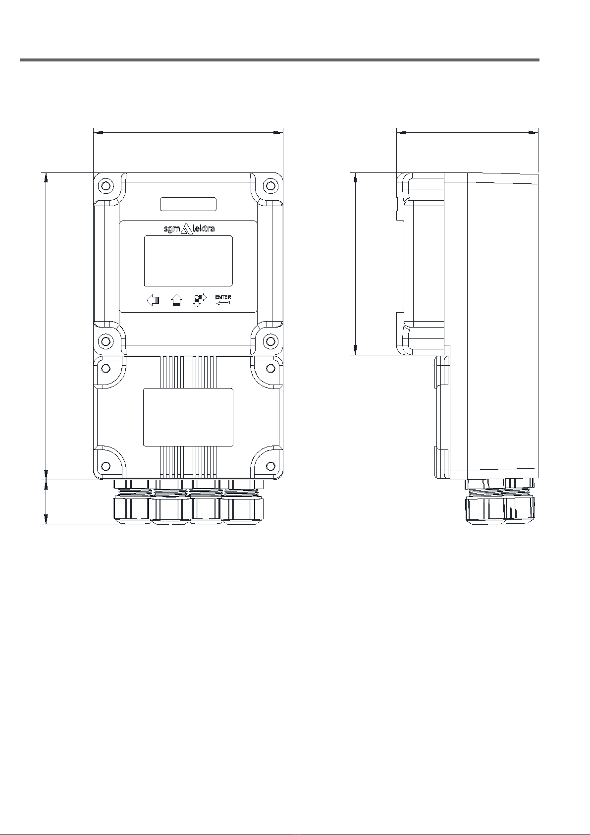
4-DIMENSIONS
4.1 MECHANICAL DIMENSIONS
20~
100
160
75
95

Page 7 of 32
www.sgm-lektra.eu
VLW602 - electrical connections
5-ELECTRICAL CONNECTIONS
0V
24VDC
L(+)
N(-)
GND
YELLOW
GREEN
BLUE
BROWN
RED
-mA
+mA
4-20mA
A(RS485)
B(RS485)
5.1 CONNECTIONS
1) Separate the engine control cables or power cables from the VLW602 connection cables.
2) Remove the caps from the cable glands and open the cover by unscrewing the screws.
3) Lead the cables into the transmitter through the cable glands.
4) Close the cap and tighten the cable glands
5.2 RECOMMENDATIONS FOR EXTERNAL MOUNTING
To avoid the humidity infiltration inside the housing is recommended:
- For electrical connections, tighten the PG9 cable gland..
- fully tighten the cap.
- position the cable so that it forms a downward curve at the PG9 output; in this way the condensation and/or
rain water will tend to drop from the curve bottom.
- The two central cable glands are arranged for the PTU sensor connection cables.

Page 8 of 32 www.sgm-lektra.com
5.3 Connection
N(-)
GND
YELLOW
GREEN
BLUE
BROWN
RED
-mA
+mA
4-20mA
A(RS485)
B(RS485)
0V
24VDC
L(+)
N(-)
GND
L(+)
+mA
-mA
VLW602 - electrical connections
Page 9 of 32
www.sgm-lektra.eu
VLW602 - configuration and calibration
6-CONFIGURATION AND CALIBRATION
Via the VLW602 the operator can: access any transmitter function, change configuration parameter settings and other
functions.
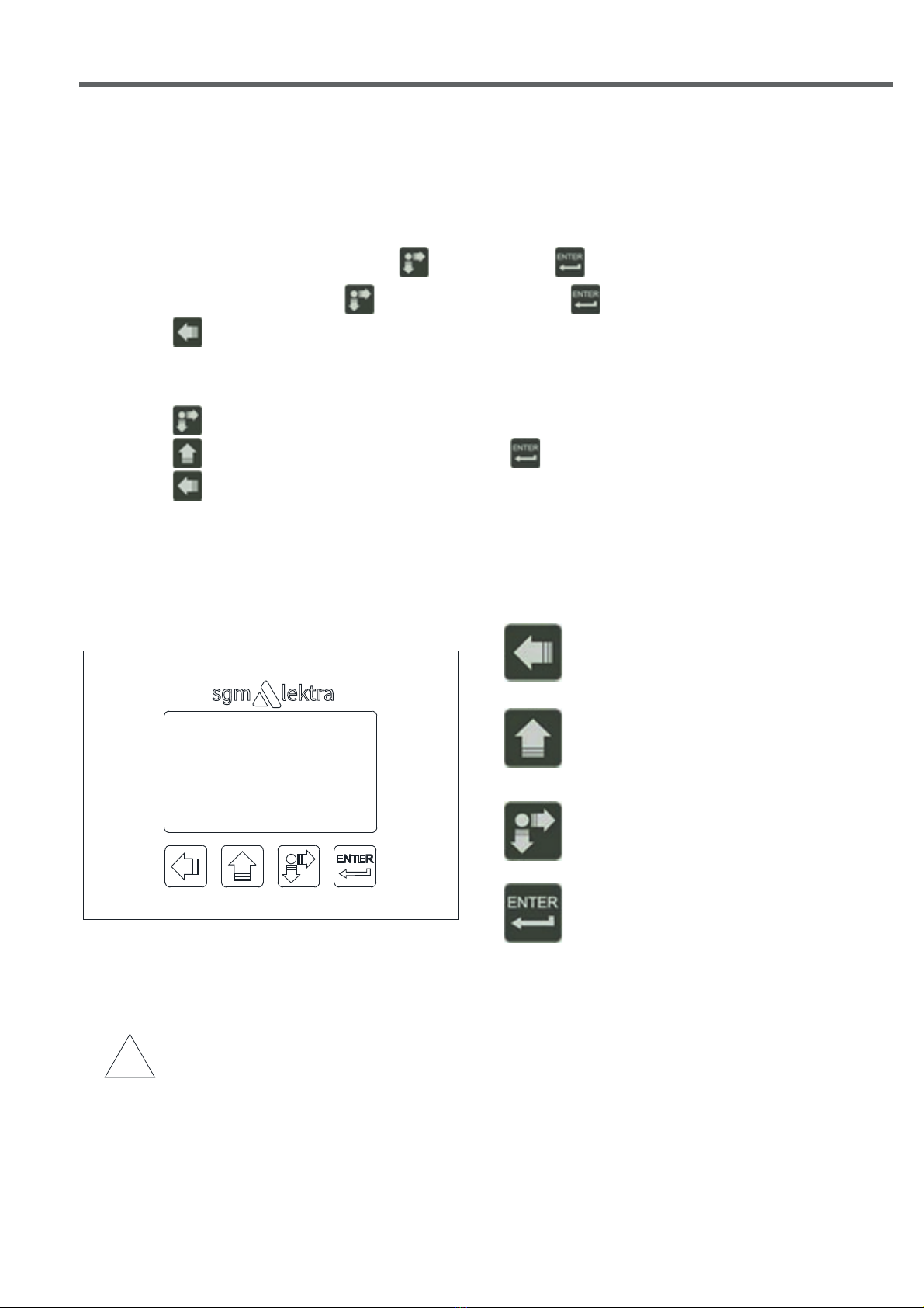
6.1 VLW602FEATURES
The VLW602 program module has 4 buttons which allow to perform all operational, control and programming
instrument functions.
In the configuration menus, is possible:
1. Submenus and parameters access; press to select and press to access.
2. Parameter options choice: Press to select the option and press to store the option.
Press to exit without storing.
3. Configure the parameter values; in some parameters the configuration is done by setting a value
(eg., in the SET DISTANCE 4mA parameter is possible to change the the corresponding distance value, in mm):
press to select the digit to be modified (the digit is highlighted in inverse ),
press to change the high lighted digits number, press to save the set value and exit automatically.
Press to exit without storing.
!
LEFT ARROW button:
• Exit configuration
• Back to previous menu
• Echo map (from RUN mode)
UP ARROW button:
• Parameter values modification
• Parameter scroll
SCROLL button:
• Cursor movement (to the right)
• Parameter scroll
ENTER button:
• Configuration access
• Options confirmation
• Parameters values confirmation
Displayed at the top alerts that there is a generic error; press SCROLL to show the message that
indicates the present error type.
The PTU5_ returns automatically to RUN mode.
!
Displayed at the top alert thet the PTU sensor is not communicating with VLW602.

Page 10 of 32 www.sgm-lektra.com
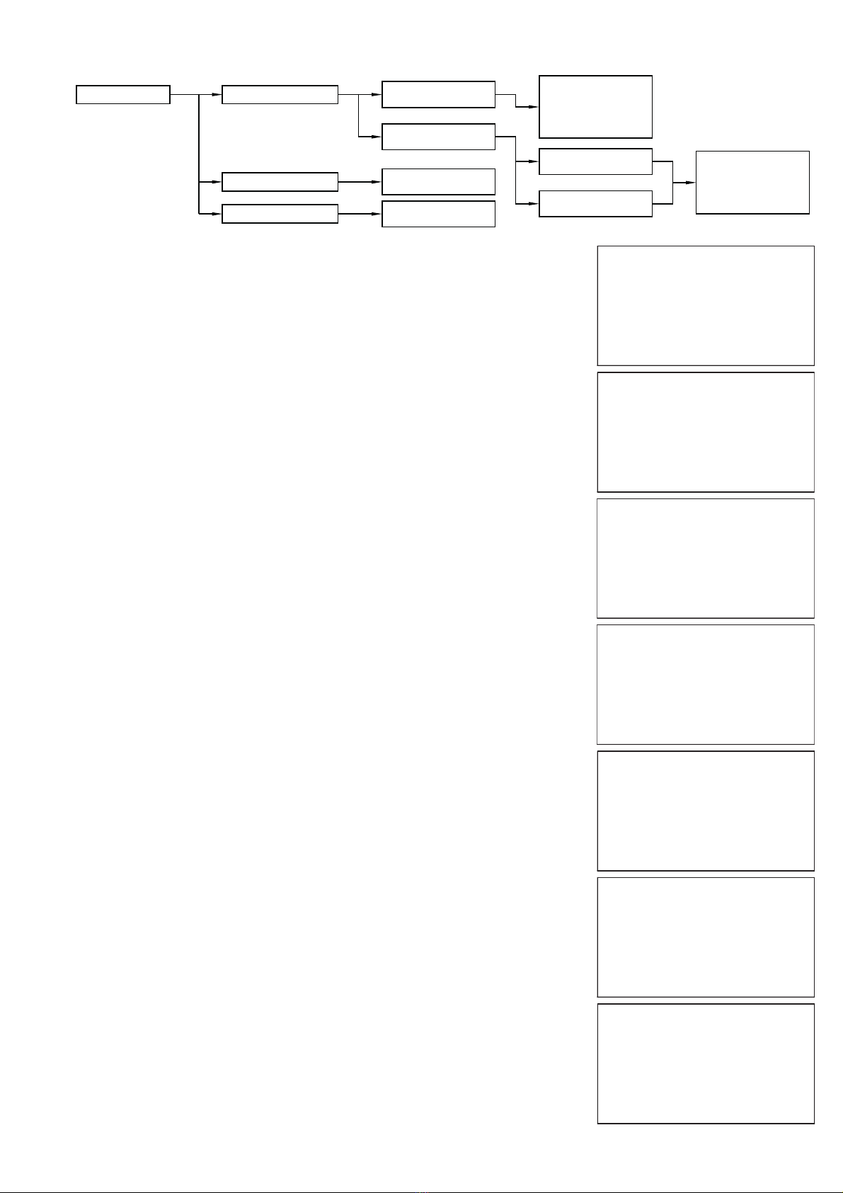
Quick Setup Set Distance 4mA
Set Distance 20mA
Medium
$'/ -* Ȃ$$ )/
Blind Distance
Display
Set Distance 4mA
0000 mm
Set Distance 20mA
0000 mm
$'/ -* Ȃ$$ )/
000
Blind Distance
0000 mm
Distace mm
Level mm
Level %
Output mA
Temperature °C
Parameter Default Values
1500mm (PTU50 1.5mt max)
6000mm (PTU51 6mt max)
12000mm (PTU56 12mt max)
Liquids
20
Distance mm
100mm (PTU50 1.5mt max)
400mm (PTU51 6mt max)
600mm (PTU56 12mt max)
050mm (PTU50 1.5mt max)
300mm (PTU51 6mt max)
500mm (PTU56 12mt max)
Medium
>Liquids
Solids
Liquids Pipe
VLW602 - quick setup
7.2 - QUICK SETUP MODE
From “RUN” mode press ENTER to access the Quick Setup menu.
Select the parameters by moving the cursor with SCROLL, and confirm with ENTER;
press LEFT ARROW to exit.
DISTANCE 4mA
DISTANCE 20mA
MEDIUM
FILTER COEFFICENT
BLIND DISTANCE
DISPLAY
Ź
4321
D
mm
7-QUICK SETUP
7.1 - Quick Setup menu structure
Page 11 of 32
www.sgm-lektra.eu
VLW602 - quick setup
7.2.1 SET DISTANCE 4mA
Press ENTER to display the distance value associated with 4mA output.
Use SCROLL and UP ARROW to modify that value; in the example the 4mA
distance is 3500mm.
Press ENTER to confirm.
DISTANCE 4mA
DISTANCE 20mA
MEDIUM
FILTER COEFFICENT
BLIND DISTANCE
DISPLAY
Ź
3500 mm
SET DISTANCE 4mA
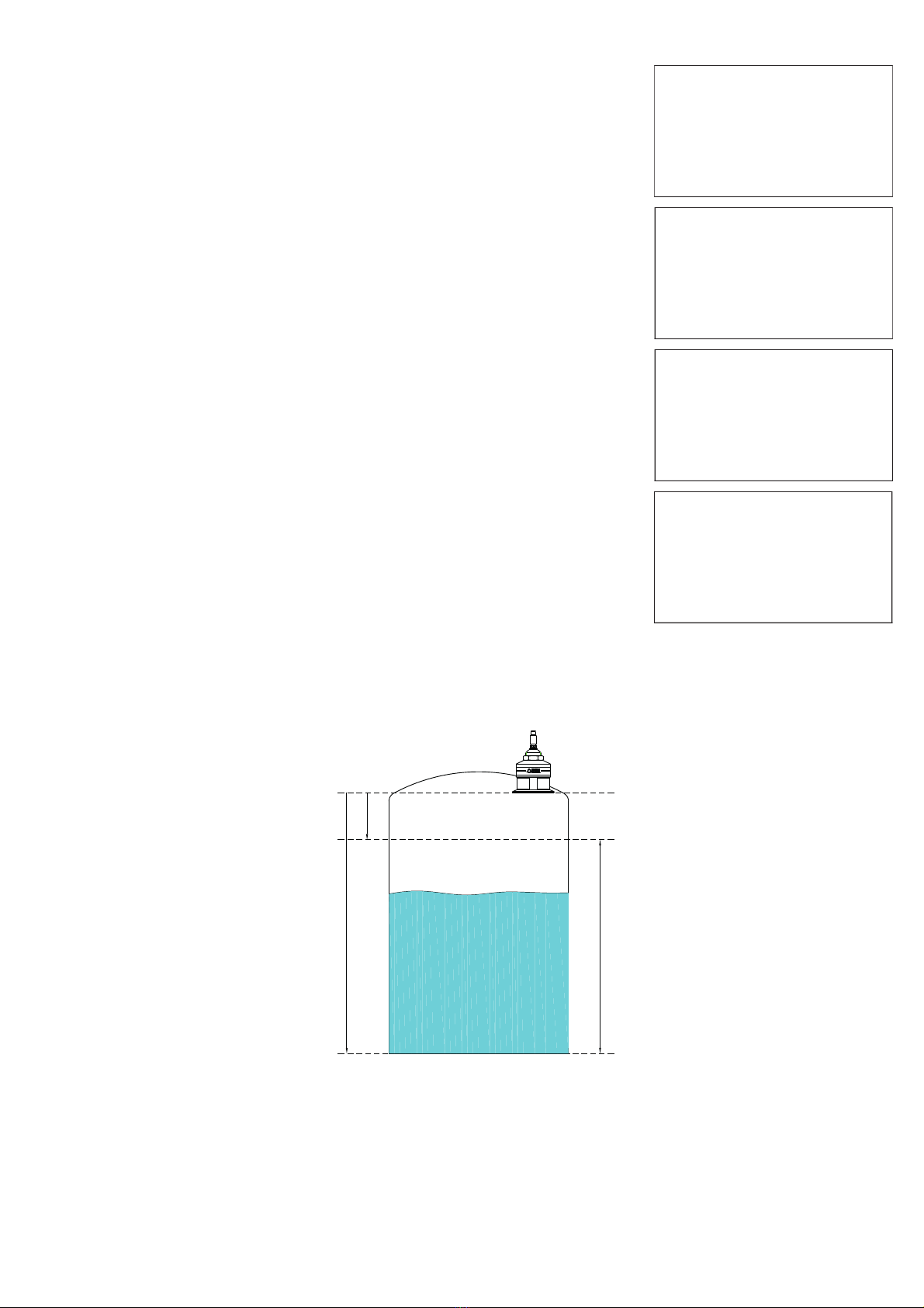
7.2.2 SET DISTANCE 20mA
Press ENTER to display the distance value associated with 20mA output.
Use SCROLL and UP ARROW to modify that value; in the example the 20mA
distance is 500mm.
Press ENTER to confirm..
DISTANCE 4mA
DISTANCE 20mA
MEDIUM
FILTER COEFFICENT
BLIND DISTANCE
DISPLAY
Ź
0500 mm
SET DISTANCE 20mA
100%
0%
Distance 20mA
Distance 4mA
Level measurament
Referent point
PTU50-51-56

Page 12 of 32 www.sgm-lektra.com
VLW602 - quick setup
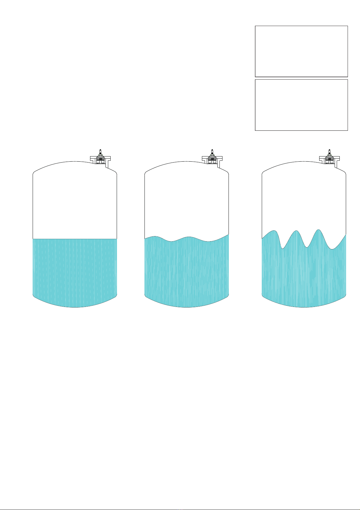
7.2.3 MEDIUM
Press ENTER to display the previous setting.
Press SCROLL to select the medium type.
Press ENTER to confirm.
DISTANCE 4mA
DISTANCE 20mA
MEDIUM
FILTER COEFFICENT
BLIND DISTANCE
DISPLAY
Ź
LIQUIDS
SOLIDS
LIQUIDS PIPE
Ź
LIQUIDS SOLIDS LIQUIDS PIPE
Page 13 of 32
www.sgm-lektra.eu
7.2.4 FILTER COEFFICIENT
Press ENTER.
Use SCROLL and UP ARROW to modify the value. Input a value from 1 to 99.
1 maximum speed, 99 maximum slowness.
The function is deactivated with 0 (immediate response).
Press ENTER to confirm.
DISTANCE 4mA
DISTANCE 20mA
MEDIUM
FILTER COEFFICENT
BLIND DISTANCE
DISPLAY
Ź
20
FILTER COEFFICENT
Fast resp. 5÷10 Normal resp. 20 Slow resp. 40÷100
VLW602 - quick setup

Page 14 of 32 www.sgm-lektra.com
BLIND ZONE
BLIND
DISTANCE
Referent point
PTU50-51-56
7.2.5 BLIND DISTANCE
Press ENTER. The BLIND ZONE is used to avoid undesired measures near to the
transmitter.
Use SCROLL and UP ARROW to modify the value. Press ENTER to confirm.
The minimum value is 50mm (PTU50), or 300mm (PTU51) or 500mm (PTU56).
DISTANCE 4mA
DISTANCE 20mA
MEDIUM
FILTER COEFFICENT
BLIND DISTANCE
DISPLAY
Ź
0250 mm
BLIND DISTANCE
7.2.6 DISPLAY
Press ENTER to access the settings change.
With the SCROLL button is possible to select the data to display.
Press ENTER to confirm.
DISTANCE 4mA
DISTANCE 20mA
MEDIUM
FILTER COEFFICENT
BLIND DISTANCE
DISPLAYŹ
DISTANCE mm
LEVEL mm
LEVEL %
OUTPUT mA
TEMPERATURE °C
Ź
VLW602 - quick setup

Page 15 of 32
www.sgm-lektra.eu
VLW602 - quick setup
7.3 - ECHO MAP
Pressing LEFT ARROW, from RUN mode, to access directly to the echoes digital map display, which are in
PTU50-51-56 receiving.
This function is useful for:
- properly orient the transducer pointing.
- verify the echoes in acquisition correctness.
- identify any false echo signals that may cause measurement errors.
15432
m
D 721mm G 020 57.2KHz
The rectangle placed at the echo line base,
indicates the measurement range within which the
echo signal in reception is considered always valid for
the distance measurement. This interval value is varia-
ble depending on the measurement conditions: min. ±
2.5% of the measured distance.
Echo signal normalization
threshold
Measured distance from
PTU50-51-56 in real time
Measure status Echo frequency

Page 16 of 32 www.sgm-lektra.com
VLW602 - advanced configuration
8-ADVANCED CONFIGURATION
8.1 - “SETUP” MENU
SETUP
SET DISTANCE 20mA
SET DISTANCE 4mA
MEDIUM
FILTER COEFFICIENT
BLIND DISTANCE
ACTUAL LEV 4mA
ACTUAL LEV 20mA
SET DISTANCE 4mA
0000mm
SET DISTANCE 20mA
0000mm
LIQUIDS
SOLIDS
LIQUIDS PIPE
FILTER COEFFICIENT
000
BLIND DISTANCE
0000mm
OK to confirm
8.2 - SETUP
From “RUN” mode, holding down UP ARROW, press ENTER to the
advanced configuration mode access.
Press SCROLL to select the menu and press ENTER to access.
Press LEFT ARROW to exit.
SETUP
DISPLAY
DIAGNOSTIC
SERVICE
PROBE INFO
UNIT INFO
Ź
SET DISTANCE 4mA
SET DISTANCE 20mA
MEDIUM
FILTER COEFFICIENT
BLIND DISTANCE
ACTUAL LEV 4mA
ACTUAL LEV 20mA
Ź
3321 mm
DISTANCE
1679 mm
LEVEL

Page 17 of 32
www.sgm-lektra.eu
VLW602 - advanced configuration
8.2.1 - SET DISTANCE 4mA
Position the cursor on DISTANCE 4mA, press ENTER to access.
Use UP ARROW and SCROLL to modify the value.
Press ENTER to confirm.
LEFT ARROW to exit without changes
Default value: 1500mm (PTU50 range 1,5mt), 6000mm (PTU51 range 6mt.)
or 12000mm (PTU56 range 12mt)
SET DISTANCE 4mA
SET DISTANCE 20mA
MEDIUM
FILTER COEFFICIENT
BLIND DISTANCE
ACTUAL LEV 4mA
ACTUAL LEV 20mA
Ź
5000 mm
SET DISTANCE 4mA
8.2.2 - SET DISTANCE 20mA
Position the cursor on DISTANCE 20mA, press ENTER to access.
Use UP ARROW and SCROLL to modify the value.
Press ENTER to confirm.
LEFT ARROW to exit without changes
Default value: 100mm (PTU50 range 1,5mt), 400mm (PTU51 range 6mt.)
or 600mm (PTU56 range 12mt)
0300 mm
SET DISTANCE 20mA
SET DISTANCE 4mA
SET DISTANCE 20mA
MEDIUM
FILTER COEFFICIENT
BLIND DISTANCE
ACTUAL LEV 4mA
ACTUAL LEV 20mA
Ź
8.2.3 - MEDIUM
Position the cursor on MEDIUM, press ENTER to access.
3 configurations are possible:
LIQUIDS - liquids measurement
SOLIDS - granular solids measurement
LIQUIDS PIPE - liquids measurement in pipe reference
Press SCROLL to select the product type.
Press ENTER to confirm.
LEFT ARROW to exit without changes
Default value: LIQUIDS
LIQUIDS
SOLIDS
LIQUIDS PIPE
Ź
SET DISTANCE 4mA
SET DISTANCE 20mA
MEDIUM
FILTER COEFFICIENT
BLIND DISTANCE
ACTUAL LEV 4mA
ACTUAL LEV 20mA
Ź
8.2.4 - FILTER COEFFICIENT
Position the cursor on FILTER COEFFICIENT, press ENTER to access.
Enter a value from 1 to 99: 1 maximum speed, 99 maximum slowness.
The function is deactivated with 0 (immediate response)
Use UP ARROW and SCROLL to modify the value.
Press ENTER to confirm.
LEFT ARROW to exit without changes
Default value: 10
20
FILTER COEFFICIENT
SET DISTANCE 4mA
SET DISTANCE 20mA
MEDIUM
FILTER COEFFICIENT
BLIND DISTANCE
ACTUAL LEV 4mA
ACTUAL LEV 20mA
Ź

Page 18 of 32 www.sgm-lektra.com
VLW602 - advanced configuration
8.2.5 - BLIND DISTANCE
Position the cursor on DISTANCE 4mA, press ENTER to access.
Represent the “BLIND ZONE”
Input the desired value in order to avoid measures near the surface of the
sensor (if necessary).
The minimum value is 250mm (6m vers.) or 400mm (10m vers.)
Use UP ARROW and SCROLL to modify the value.
Press ENTER to confirm.
LEFT ARROW to exit without changes
Default values: 50mm (PTU50), 300mm (PTU51) or 500mm (PTU56)
SET DISTANCE 4mA
SET DISTANCE 20mA
MEDIUM
FILTER COEFFICIENT
BLIND DISTANCE
ACTUAL LEV 4mA
ACTUAL LEV 20mA
Ź
0600 mm
BLIND DISTANCE
8.2.6 - ACTUAL LEV. 4mA
Position the cursor on ACTUAL LEV. 4mA, press ENTER to access.
Self distance learning function that is associated with the 4mA (lower
value). Make sure that the level corresponds to 0%, ENTER to associate the
actual measure with 4mA output value;
OK TO CONFIRM .
LEFT ARROW to exit without changes.
SET DISTANCE 4mA
SET DISTANCE 20mA
MEDIUM
FILTER COEFFICIENT
BLIND DISTANCE
ACTUAL LEV 4mA
ACTUAL LEV 20mA
Ź
8.2.7 - ACTUAL LEV. 20mA
Position the cursor on ACTUAL LEV. 20mA, press ENTER to access.
Self distance learning function that is associated with the 20mA (upper value).
Make sure that the level corresponds to 100%, ENTER to associate the actual
measure with 20mA output value;
OK TO CONFIRM .
LEFT ARROW to exit without changes.
SET DISTANCE 4mA
SET DISTANCE 20mA
MEDIUM
FILTER COEFFICIENT
BLIND DISTANCE
ACTUAL LEV 4mA
ACTUAL LEV 20mA
Ź
Page 19 of 32
www.sgm-lektra.eu
VLW602 - advanced configuration
8.3 “DISPLAY” menu
8.4 - DISPLAY
From “RUN” mode, holding down UP ARROW, press ENTER to access
Position the cursor on DISPLAY and press ENTER
Select the parameters by moving the cursor with SCROLL and confirm with ENTER
8.4.1 - DISPLAY VALUES
Position the cursor on DISPLAY VALUES, press ENTER to access.
Itʼs possible to select if one value with big digits or two values are shown on the
display in “RUN” mode.
Select the parameters by moving the cursor with SCROLL and confirm with
ENTER.
LEFT ARROW to exit without changes
8.4.1.1 - 1 VALUE
Position the cursor on 1 VALUE, press ENTER to access.
Only one value is displayed; itʼs possible to choose from 5 parameters.
With the SCROLL button you can select data to display.
Press ENTER to confirm.
LEFT ARROW to exit without changes
2013
D
mm
DISPLAY DISPLAY VALUES
LCD CONTRAST
WELCOME TEXT
>1 VALUE
2 VALUES
1 VALUE
>2 VALUES
LCD CONTRAST
00
WELCOME TEXT
SGM-LEKTRA PTU5x
DISTANCE mm
LEVEL mm
LEVEL %
OUTPUT mA
TEMPERATURE °C
>PRIMARY VALUE
SECONDARY VALUE
PRIMARY VALUE
>SECONDARY VALUE
DISTANCE mm
LIVEL mm
LIVEL %
OUTPUT mA
TEMPERATURE °C
DISPLAY VALUES
LCD CONTRAST
WELCOME TEXT
Ź
SETUP
DISPLAY
DIAGNOSTIC
SERVICE
PROBE INFO
UNIT INFO
Ź
DISPLAY VALUES
LCD CONTRAST
WELCOME TEXT
Ź
1 VALUE
2 VALUES
Ź
1 VALUE
2 VALUES
Ź
DISTANCE mm
LEVEL mm
LEVEL %
OUTPUT mA
Ź

Page 20 of 32 www.sgm-lektra.com
8.4.1.2 - 2 VALUE
Position the cursor on 2 VALUE, press ENTER to access.
Two values are displayed; itʼs possible to choose which one is the
primary and which is the secondary, each with a choice of 5 parameters.
With the SCROLL button you can select data to display.
Press ENTER to confirm.
LEFT ARROW to exit without changes
VLW602 - advanced configuration
1 VALUE
2 VALUES
Ź
PRIMARY VALUE
SECONDARY VALUE
Ź
DISTANCE mm
LEVEL mm
LEVEL %
OUTPUT mA
Ź
PRIMARY VALUE
SECONDARY VALUE
Ź
DISTANCE mm
LEVEL mm
LEVEL %
OUTPUT mA
TEMPERATURE °C
Ź
This manual suits for next models
1
Table of contents
Popular Control Unit manuals by other brands


wtw
wtw TresCon NH4-N operating manual

Cameron
Cameron TK Installation, operation and maintenance manual

HEPER
HEPER D-LIGHT AFX 1 Installation & maintenance instructions

Telit Wireless Solutions
Telit Wireless Solutions ZE50-2.4 user guide

Renishaw
Renishaw SLM 250 Installation and operation

oventrop
oventrop mote 420 Installation and operating instructions


