manuals.online logo
Brands
  1. Home
  2. •
  3. Brands
  4. •
  5. ADTRAN
  6. •
  7. Control Unit
  8. •
  9. ADTRAN OC-3 User manual

ADTRAN OC-3 User manual

jobAid
1
DESCRIPTION
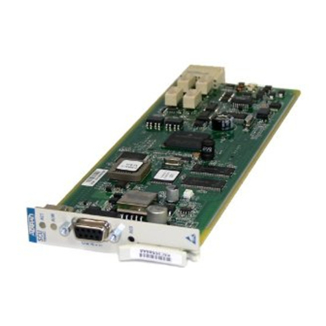
The OPTI-6100®OC-3/OC-12 Optical Multiplexer Module
(OMM312V) terminates a SONET OC-3 or OC-12 fiber circuit to
feed the OPTI-6100 MX or SMX chassis. It converts optical signals
into digital electrical signals for distribution through the
backplane to the tributary modules.
The OMM312V requires OPTI-6100 System Release 5.2 or higher,
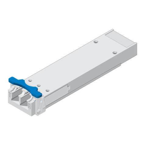
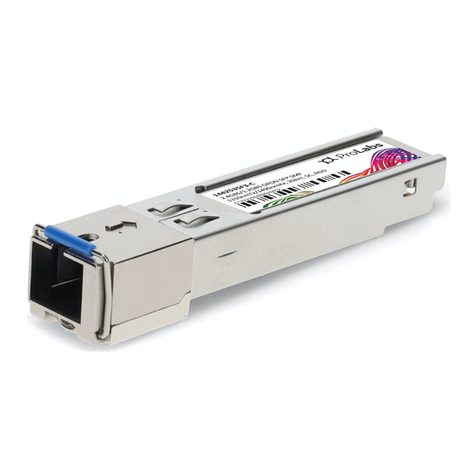
plus a small form-factor pluggable (SFP) to provide the optical
interface.
FEATURES
The OMM312V supports the following features:
SONET rates:
oOC-3 (155.52 Mbps)
oOC-12 (622.08 Mbps)
Operational modes:
oTerminal mode: 1+1 Unidirectional
oTerminal mode: 1+1 Bi-directional
oAdd/Drop Multiplexer (ADM) mode:
Unidirectional Path Switched Ring (UPSR)
oOptical Y-cable
Redundant (1+1) or non-redundant operation
Hot swap capability
Timing/synchronization options:
STATUS
OMM312V
1184571G1
ALARM
ON LINE
TEST
OPTI-6100
OC-3/OC-12 Optical Multiplexer Module
oExternal BITS timing (In/Out from chassis)
oStratum 3 clock
oTiming derived from tributary module
oReceive fiber timing
Integrated, non-blocking, any-to-any STS-3, STS-1, and VT
cross-connect
Supports 155 Mbps and 622 Mbps backplane rates
Centrally managed by the System Controller Module (SCM,
P/N 1184500Lxx)
Bridges all DCC channels between high-speed (HS) and mid-
speed (MS) interfaces and the SCM
Connections/Compatibilities
The OMM312V plugs directly into the OPTI-6100 chassis as
follows:
MX (P/N 1184501x1): HS1 or HS2
SMX (P/N 1184514x1): HS1 or HS2
LMX (P/N 1184555L1): Not supported
The data rates delivered to MS slots are as follows:
OC-3 operation: Delivers 155 Mbps to all MS slots
OC-12 operation:
oDelivers 622 Mbps to MS slots 1 and 3
oDelivers 155 Mbps to all other MS slots
CLEI: SOUIBPRL_ _ _
Product P/N: 1184571G1V
Issue Date: October 2014
Document P/N: 61184571G1V-22C
Documentation for ADTRAN Carrier Networks products is available for
viewing and download directly from the ADTRAN Support Community
website.
Go to: https://supportforums.adtran.com/welcome
Registration is required.
ADTRAN offers training courses on our products, including customized
training and courses taught at our facilities or at customer sites.
For inquiries, go to: http://adtran.com/training
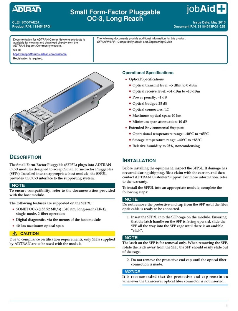
The following documents provide additional information for this product:
OPTI-6100 Installation and Turn-Up Guide
OPTI-6100 Maintenance and Troubleshooting Guide
OPTI-6100 Overview, Engineering, Applications, and Ordering Guide
OPTI-6100 TL1 Reference Guide
SFP/XFP/SFP+ Compatibility Matrix and Engineering Guide
261184571G1V-22C
2. To Install the OMM312V, refer to the figure below.
This module performs a self-test at power-up. After testing, the
LEDs indicate the current status of the module, as described in
Front Panel LEDs.
UPPER
LOWER
SFPs
The table below lists the SFPs supported on the OMM312V.
INSTALLATION
Before installation, inspect the OMM312V. If damage has
occurred during shipping, file a claim with the carrier, and then
contact ADTRAN Customer Support.
Installation Guidelines
The following are guidelines for this installation.
Remove the MS Module Blank(s) (P/N 1184505x1) from the
appropriate slot(s) of the OPTI-6100 chassis, if present.
Install the required SFP.
Identify the fiber conductors or Cat-5 cables to be terminated
on the module. Insert the connectors into the appropriate
jacks.
Do not pinch the fibers against the edge of the chassis.
Route optical fibers along the chassis fiber tray.
Installation Steps
1. Identify the fiber conductors to be terminated on the mod-
ule. Insert the connectors into the appropriate jacks. Route
the fibers according to the fiber routing diagram, above
right.
Part Number Optics/Type Wavelength Max. Span
OC-3 SFPs
1184543P1 Long Reach 1 1310 nm 40 km
1184543PG1 Long Reach 1 1310 nm 40 km
1184543P2 Intermediate Reach 1 1310 nm 15 km
1184543PG2 Intermediate Reach 1 1310 nm 15 km
1184543P3 Short Reach 1310 nm 2 km
1184543PG3 Short Reach 1310 2 km
1184543P5 Long Reach 2 1550 nm 80 km
1184543PG5 Long Reach 2 1550 nm 80 km
1442702PG1 Single‐fiber,bi‐direc‐
tional
1310 nm 20 km
1442702PG2 Single‐fiber,bi‐direc‐
tional
1550 nm 20 km
OC-12 SFPs
1184544P1 Long Reach 1 1310 nm 40 km
1184544PG1 Long Reach 1 1310 nm 40 km
1184544P2 Intermediate Reach 1 1310 nm 15 km
1184544PG2 Intermediate Reach 1 1310 nm 15 km
1184544P5 Long Reach 2 1550 nm 80 km
1442704PG1 Single‐fiber,bi‐direc‐
tional
1310 nm 15 km
1442704PG2 Single‐fiber,bi‐direc‐
tional
1550 nm 15 km
61184571G1V-22C 3
Front Panel LEDs
PROVISIONING
There are no switches or jumpers on the OMM312V module.
Provisioning is done through the craft port or through remote
access.
This module can also be remotely provisioned through TL1.
System Access
The OPTI-6100 SCM has a front-panel DB-9 connector, supplying
an RS-232 interface to a controlling terminal. The supported
terminal type is VT100 or compatible, set for:
9600 bps
8 data bits
No parity
No flow control
1 stop bit
After connection to the OPTI-6100 system, the Login screen is
displayed. To log in, enter the default Account Name (ADMIN) and
Password (PASSWORD).
To enter a menu or screen, select the desired option, and press
ENTER. To return to the previous menu, press ESC.
Label Status Indication
STATUS 


2

2
Off
Red
Yellow
Flashing Yellow
Green
Flashing Green
Lack of power or power failure
Hardware or firmware failure
Module Out of Service–Unas-
signed (OOS-UAS)
Module Out of Service–Main-
tenance (OOS-MA)
Power up and initialization
OK; Module is In Service (IS)
Firmware download in prog-
ress
ALARM 



Off
Red
Yellow
Green
LED failure or power failure
Facility or Path error, such as
Loss of Signal
Alerts present
Module operational with no
alarms
ON LINE 


Off
Yellow
Green
Module offline
Module protection inhibited
Module online
TEST 

Off
Yellow
Module not in test mode
Module is in loopback
Factory Defaults
To access OMM312V provisioning, complete the following steps:
1. Log in to the OPTI-6100
2. From the OPTI-6100 Main menu, select the OMM312V, and
press ENTER.
3. From the OMM312V menu, select Provisioning, and press
ENTER.
MAINTENANCE
The OMM312V does not require routine hardware maintenance
for normal operation. ADTRAN does not recommend that repairs
be attempted in the field. Repair services may be obtained by
returning the defective unit to ADTRAN. Field support for
software is provided through upgrade facilities.
SPECIFICATIONS
Specifications for the OMM312V are as follows:
Operates from A, B, or A and B input voltage feeds:
o±24 VDC Nominal (±20.0 VDC to ±28.3 VDC), or
o–48 VDC Nominal (–40.0 VDC to –56.7 VDC)
Extended environmental support:
oOperational temperature range: –40°C to +55°C
oStorage temperature range: –40°C to +85°C
oRelative humidity to 95%, noncondensing
CAUTION!
SUBJECT TO ELECTROSTATIC DAMAGE
OR DECREASE IN RELIABILITY
HANDLING PRECAUTIONS REQUIRED
Warranty: ADTRAN will replace or repair this product within the warranty period if it does not
meet its published specifications or fails while in service. Warranty information can be
found online at www.adtran.com/warranty.
©2014 ADTRAN, Inc. All Rights Reserved.
ADTRAN CUSTOMER CARE:
From within the U.S. 1.800.726.8663
From outside the U.S. +1 256.963.8716
PRICING AND AVAILABILITY 1.800.827.0807
*61184571G1V-22C*
SAFETY AND REGULATORY COMPLIANCE
WARNING
!
Read all warnings and cautions before installing or servicing this
equipment
CAUTION
C
This product is a Class 1 Laser that complies with FDA 21 CFR
1040.10 and 1040.11 and IEC 60825-1 and -2. The product is NRTL
Listed and CB Certified to all applicable American and European
safety standards.
CAUTION
!
Electrostatic Discharge (ESD) can damage electronic modules.
When handling modules, wear an antistatic discharge wrist
strap to prevent damage to electronic components. Place
modules in antistatic packing material when transporting or
storing. When working on modules, always place them on an
approved antistatic mat that is electrically grounded.
Per GR-1089-CORE the ADTRAN system that this product is
being deployed in is designed and intended for installation as
part of a Common Bonding Network (CBN). The ADTRAN
system that this product is being deployed in is not designed
nor intended for installation as part of an Isolated Bonding
Network (IBN).
This product is NRTL listed to all applicable UL standards.
The product meets or exceeds applicable requirements of
NEBS, Telcordia GR-63-CORE, GR-78-CORE, and GR-1089-
CORE. This product is intended for deployment in Central
Office type facilities, EEEs, EECs, and locations where the
NEC applies (e.g., Customer Premises).
This product should be installed by qualified Service
Personnel only, in an OPTI-6100 in a restricted access location.
Per GR-1089-CORE Section 9, this product does not have an
internal DC connection between battery return and frame
ground. This product can be installed in a DC-I (isolated) or
DC-C (common) installation. For installations where other
cards or the host system have internal connections between
battery return and frame ground, the system would be
intended for deployment only in a DC-C installation.
The ADTRAN system chassis frame ground terminal must be
connected to a reliable earth ground to ensure that the metal
enclosure of this product is properly grounded via the
backplane connector.
Configuration Code Input Output
PowerCode(PC) F C
TelecommunicationCode(TC) – –
InstallationCode(IC) A –
This device complies with Part 15 of the FCC rules. Operation is
subject to the following two conditions:
1. This device may not cause harmful interference.
2. This device must accept any interference received, including
interference that may cause undesired operation.
Changes or modifications not expressly approved by ADTRAN
could void the user’s authority to operate this equipment.
NOTE
This product is designed to operate with a nominal operating
voltage of –48 or ±24 VDC. The product will not be damaged
by any steady state voltage below –56.7 VDC.
When the chassis is wired for –48 VDC, the product will
power itself down if it encounters steady state voltages
below (approximately) –38 VDC.
This product is designed to meet the following environmental
classes:
ETSI EN 300 019-1-1 “Classification of environmental
conditions; Storage,” Class 1.2
ETSI EN 300 019-1-2 “Classification of environmental
conditions; Transportation,” Class 2.3
ETSI EN 300 019-1-3 “Classification of environmental
conditions; Stationary use at weather protected locations,”
Class 3.3
This product is designed to function without degradation during
exposure to all test severities per Class 019-1-3 3.3.
This product complies with ETSI EN 300 386 Electromagnetic
compatibility and Radio spectrum Matters (ERM); Telecommunication
network equipment; Electromagnetic Compatibility (EMC) require-
ments.
This product meets EU RoHS Directive 2002/95/EC and/or
applicable exemptions. Refer to www.adtran.com for further
information on RoHS/WEEE.

This manual suits for next models

1

Other ADTRAN Control Unit manuals

ADTRAN Total Access 300 Series User manual

ADTRAN

ADTRAN Total Access 300 Series User manual

ADTRAN SFP+ 10G User manual

ADTRAN

ADTRAN SFP+ 10G User manual

ADTRAN Total Access 1500 FT1 DP Instruction Manual

ADTRAN

ADTRAN Total Access 1500 FT1 DP Instruction Manual

ADTRAN Type 400 User manual

ADTRAN

ADTRAN Type 400 User manual

ADTRAN NetVanta Octal T1/E1 Wide Module User manual

ADTRAN

ADTRAN NetVanta Octal T1/E1 Wide Module User manual

ADTRAN 1442442F1 User manual

ADTRAN

ADTRAN 1442442F1 User manual

ADTRAN Octal E&M User manual

ADTRAN

ADTRAN Octal E&M User manual

ADTRAN 1200791L1 User manual

ADTRAN

ADTRAN 1200791L1 User manual

ADTRAN Total Access 300 Series User manual

ADTRAN

ADTRAN Total Access 300 Series User manual

ADTRAN SFP User manual

ADTRAN

ADTRAN SFP User manual

ADTRAN Quad T1 User manual

ADTRAN

ADTRAN Quad T1 User manual

ADTRAN Total Access 300 Series Product manual

ADTRAN

ADTRAN Total Access 300 Series Product manual

ADTRAN 1200068L1 HS Series User manual

ADTRAN

ADTRAN 1200068L1 HS Series User manual

ADTRAN T400 Maintenance and service guide

ADTRAN

ADTRAN T400 Maintenance and service guide

ADTRAN E1 User manual

ADTRAN

ADTRAN E1 User manual

ADTRAN E220 HFAC HDSL Instruction Manual

ADTRAN

ADTRAN E220 HFAC HDSL Instruction Manual

ADTRAN Total Access 1500 Instruction Manual

ADTRAN

ADTRAN Total Access 1500 Instruction Manual

ADTRAN 1200261L1 User manual

ADTRAN

ADTRAN 1200261L1 User manual

ADTRAN Total Access 300 User manual

ADTRAN

ADTRAN Total Access 300 User manual

ADTRAN 1200065L1-1 User manual

ADTRAN

ADTRAN 1200065L1-1 User manual

ADTRAN T200 H2TU-R User manual

ADTRAN

ADTRAN T200 H2TU-R User manual

ADTRAN Job Aid+ 1442940G1 User manual

ADTRAN

ADTRAN Job Aid+ 1442940G1 User manual

ADTRAN SFP GPON ONU User manual

ADTRAN

ADTRAN SFP GPON ONU User manual

ADTRAN Job Aid+ 1442707G1 User manual

ADTRAN

ADTRAN Job Aid+ 1442707G1 User manual

Popular Control Unit manuals by other brands

Moxa Technologies PT-G503-PHR-PTP-HV user manual

Moxa Technologies

Moxa Technologies PT-G503-PHR-PTP-HV user manual

Beninca CP.BISON 35 OTI L manual

Beninca

Beninca CP.BISON 35 OTI L manual

Carlisle DeVilbiss AG362P Series Service manual

Carlisle

Carlisle DeVilbiss AG362P Series Service manual

Hayward OmniPL HLBPRO4SW installation manual

Hayward

Hayward OmniPL HLBPRO4SW installation manual

Sanhua RFKH Series instructions

Sanhua

Sanhua RFKH Series instructions

Toshiba IK-HD1E instruction manual

Toshiba

Toshiba IK-HD1E instruction manual

schmersal SRB-E-212ST operating instructions

schmersal

schmersal SRB-E-212ST operating instructions

WEG Anybus Installation, operation and configuration instructions

WEG

WEG Anybus Installation, operation and configuration instructions

IntelliControl ICS IM-NET user guide

IntelliControl ICS

IntelliControl ICS IM-NET user guide

Asutec ASU-400 operating manual

Asutec

Asutec ASU-400 operating manual

AXIOMTEK AX12270 user manual

AXIOMTEK

AXIOMTEK AX12270 user manual

National Instruments NI 9234 Getting started

National Instruments

National Instruments NI 9234 Getting started

Anritsu Network Master MT9090A Series Operation manual

Anritsu

Anritsu Network Master MT9090A Series Operation manual

Satel INT-VG manual

Satel

Satel INT-VG manual

INTERNATIONAL CARBONIC PF-2-PB installation manual

INTERNATIONAL CARBONIC

INTERNATIONAL CARBONIC PF-2-PB installation manual

Küschall Mentor manual

Küschall

Küschall Mentor manual

PERSTA DRI 21 operating instructions

PERSTA

PERSTA DRI 21 operating instructions

Fuji Electric IGBT-IPM X Series Applications manual

Fuji Electric

Fuji Electric IGBT-IPM X Series Applications manual

manuals.online logo
manuals.online logoBrands
  • About & Mission
  • Contact us
  • Privacy Policy
  • Terms and Conditions

Copyright 2025 Manuals.Online. All Rights Reserved.