Shaefer lcd 240-2 series User manual
Kapitelbezeichnung
Kapitelbezeichnung
X.X Unterpunkt
LCD 240-2VS
LCD 240-2VP
LCD 240-2HS
LCD 240-2HSC
LCD 240-2HP
LCD 240-2HPC
User manual LCD 240-2xx

2
Kapitelbezeichnung
Kapitelbezeichnung
X.X Unterpunkt
SCHAEFER GmbH
Winterlinger Str. 4
72488 Sigmaringen
Germany
Phone +49 7571 722-0
Fax +49 7571 722-99
info@ws-schaefer.de
www.ws-schaefer.de
Support
If you have any questions regarding this product please contact:
Phone +49 7571 722-51
Fax +49 7571 722-99
Copyright
Duplication (copy, print, microfilm or any other form) as well
as electronic spreading of this document
is only permitted after formal writting consent of SCHAEFER GmbH.
SCHAEFER GmbH reserves the right to carry out alterations
of technical details without prior notice.
For all transactions our General Conditions of Sale
and Delivery shall be applicable.
All rights reserved.
Ress. 012267
Revision: 2009-04-14

3
Index
1Introduction ..................................................... 4
2Display items,
symbols and fields .......................................... 4
3Electrical connections ................................. 5
4Electrical adjustment .................................... 6
5Configuration ................................................... 6
6Setup menu ...................................................... 7
7Assembly dimension....................................... 8
8Available versions of LCD240 .................... 9
8.1 LCD 240 vertical series ................................... 9
8.2 LCD 240 horizontal series.............................. 9
9Tecnical information.................................... 10
9.1 Fuctional specifications ............................... 10
9.2 Display module specifications.................... 10
9.3 Electrical connections.................................... 11
9.4 Configuration................................................... 11
10 Other devices wired in parallel .............. 12
11 VEBUS A1 -
Parallel zu seriell Konverter ..................... 14
11.1 Description....................................................... 14
11.2 Features............................................................. 14
11.3 System block diagramm............................... 15
11.4 Connection....................................................... 16
11.4.1 Electrical connections................................... 17
11.5 Function............................................................ 18
11.6 Electrical adjustment.................................... 18
11.7 Size and environment................................... 18
Index
User manual LCD 240-2xx

4
1Introduction
Note Available features depend on
urchased device version. All here
described features are not available in
all device versions.
LCD240 is a graphic LCD display with a horizontal
resolution of 128 by 240 and vertical resolution of
240 by 128 pixels. The display is optimized for lift
applications. It can be assembled either to a car or to
a level. It can present floor markings, direction ar-
rows and other graphical symbols needed for special
indications. Also other information, such as time and
date, a company logo or “floor info pictures”, can be
presented on specific versions. The user editable floor
info pictures enable presentation of any useful infor-
mation associated with certain floor(s) in addition to
a regular car position indication.
2 Display items, symbols and fields
Display is divided to four sub-areas. Names of these
fields are as follows:
Arrow/symbol field (80 x 96)
Floor marking field (48 x 96)
Logo field (12 floor info pictures only available for
LCD 240 HXC) (160 x 32)
Date and time field (only available for version HX)
Intorduction
Display items, symbols and fields
LCD 240-2xx
In normal situation an arrow is displayed in the
“arrow/symbol field” and a floor marking is displayed
in the “floor marking field”.
Appearance of the arrows can be either automatic or
externally controlled. Selection is made in the setup
menu.
When the external mode (“EXT”) is selected, appea-
rance and direction of arrow is controlled by 2 inputs
ARR-UP and ARR-DOWN (J2 / 13…14). Input
B5/MOVE (J2 / 6) activates arrow scrolling.

5
When the automatic arrow function is selected
(“AUTO”), the microcontroller continuously observes
the car position status input. In case of any change it
evaluates the direction of car movement and presents
an arrow pointing to that direction. When the floor
code stop changing, the arrow is blanked after
3 seconds.
LCD240 is capable to present 4 different symbols.
Their appearance is controlled by 4 symbol indication
inputs (J2 / 7…10). In addition, the symbol number
4 can be configured to appear when the car is in a
certain floor.
Symbols have priority: symbol number 3 overrides
symbol number 4, symbol number 2 overrides symbols
number 3 and 4, etc. Normally (and as factory default)
symbol number 1 is used for fire alarm, 2 for over-
weight and 3 for service. Own symbols can be edited
and downloaded by means of LCD240-2xx
Configurator software.
When any of the 4 symbols is displayed, it appears in
the “arrow/symbol field”. Arrow and floor marking are
both displayed in the “floor marking field”
Optional “floor info pictures” appear always in the
logo field and also optional date and time appear in
the “date and time field”.
3Electrical connections
Supply voltage (12V…24V DC) is applied to J1 connec-
tor. The device is controlled through a 14-pin connec-
tor (J2).
The connector has:
5 inputs (J2 / 1…5) for the position status,
4 inputs (J2 / 7…10) for the symbol indications,
2 inputs (J2 / 13…14) for the direction arrows and
1 input (J2 / 6) that activates the arrow scrolling
Refer to “Electrical specifications” for voltage levels
and other details.
Electrical connections
LCD 240-2xx
6
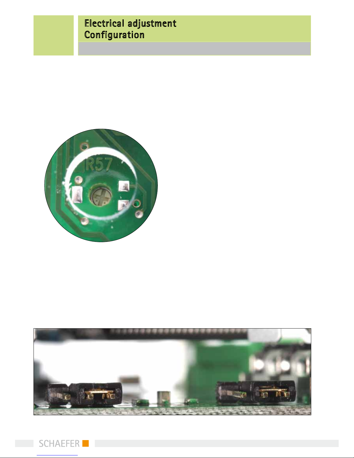
4Electrical adjustment
LCD display contrast can be adjusted by trimming
potentiometer R57. Default contrast setting is
made in factory.
5Configuration
Device can be configured in two different ways: By
means of devices own setup menu or with “LCD240-
2xx Configurator” PC-software. We recommend using
LCD240-2xx Configurator software; it is easier and
more illustrative.
“Programming” must be enabled (ie. PROG ON), when
programming the device with LCDtool. After program-
ming, the mode has to be disabled (OFF).
When programming mode is “off”, the pin connector
is active.
“Emergency info picture” parameter is used for se-
lecting the picture to be shown in the center of the
display when power failure occurs. There are three
pictures available
Electrical adjustment
Configuration
LCD 240-2xx
Two jumpers should be set to match the input signal
polarity. J8 is for the position status inputs and J4 for
the others. When changing the jumper positions, first
disconnect the device from the power supply, then
change the jumper positions and after that connect
the device back to power supply. This is because the
device automatically adapts to different input polari-
ties by reading the jumper positions to memory when
power is switched on.

7
6Setup Menu
With the aid of the setup menu the user can make
changes to certain properties of the device. Three
push buttons are assigned to browsing of the menu.
Pressing the SET push button for at least 3 seconds
activates the setup menu.
If there are more than two possible values, FW steps
to the next value and BW to the previous one. Value
is stored by pressing the SET button. Text “STORED” is
displayed and device returns to menu browsing
mode. If browsing is paused (no key is pressed) for 10
seconds, device returns from setup menu to standard
display mode.
Setup Menu:
• Inputcoding(BIN/GRAY)
• Logographics(OFF/ON)
• Programming(PROGOFF/ON)
• PowerFailurePolarity(PFPOLAR0/1)
• Arrowinputselection(EXT/AUTO)
• Emergencyinfopicture(EMERINFO0…2)
• Floormarks(BUS00…BUS31)
• Time/Date
Menu items are scrolled by buttons FW (forward) and
BW (backward) and selected by SET button. When
selected, pressing the FW button toggles between
values.
While editing floor marks there is one more step nee-
ded. Floor mark consists of up to two characters, so
the first pressing of SET button makes first character
editable by buttons FW and BW. Second pressing di-
rects editing to second character and finally the value
is stored by third pressing of the SET button like
usually.
Setup Menu
LCD 240-2xx
8
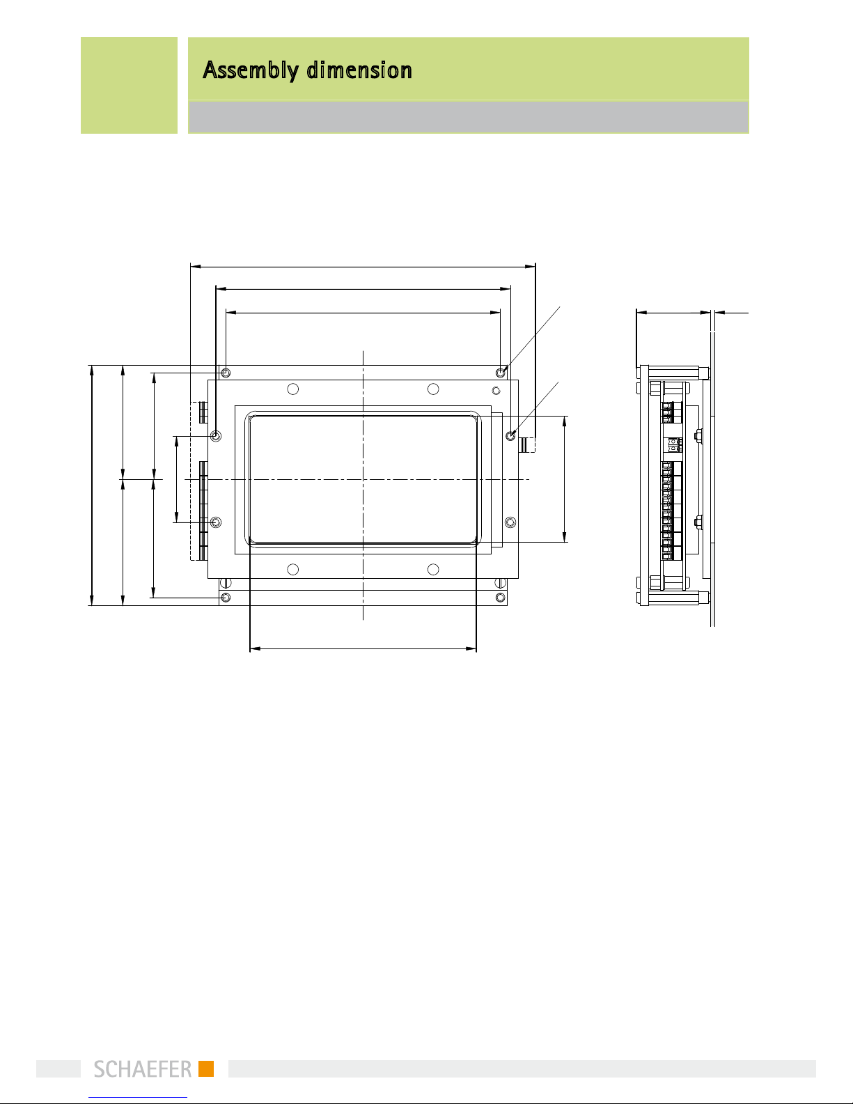
Assembly dimension
LCD 240-2xx
7Assembly dimension
172
137±0.1
147±0.1
120
57
63
53±0.1
59 ±0.1
43±0.1
113
63
37 2(3)
Schweißbolzen
M3 x 8
Schweißbolzen
M3 x 10
9
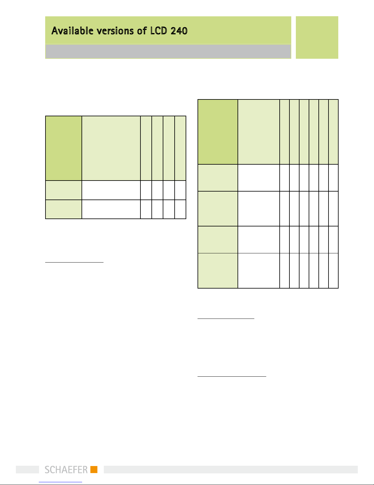
8Available versions of LCD 240
8.1 LCD 240 vertikal series
Product
name
Description
Emergency info
automatic arrow
programmable
Gong
LCD 240-
2VS
Basic version with
VEBUS interface XXXX
LCD 240-
2VP
Basic version with
parallel connection XXX
Description:
LCD 240 basic version
has three fields named as follows:
•Floormarkingfield(maximum2digits)
•Arrow/symbolfield
•Logofield
All programming can be made with the optional PC-
software (LCD240-2xx Configurator).
8.2 LCD 240 horizontal series
Product
name
Description
Emergency info
Date and time
Floor info pictures
automatic arrow
programmable
Gong
LCD 240-
2HS
Basic version
with VEBUS
interface
X X X X
LCD 240-
2HSC
Extended
version with
VEBUS inter-
face
XXXXXX
LCD 240-
2HP
Basic version
with parallel
connection
X X X
LCD 240-
2HPC
Extended
version with
parallel con-
nection
XXXXX
Description:
LCD 240 basic version
has three fields named as follows:
•Floormarkingfield(maximum2digits)
•Arrow/symbolfield
•Logofield
LCD 240 extended version has additional:
•Dateandtimefield
The extended version can show floor pictures (adver-
tisement, small Logo, small text (160x32)) in the Logo
field. All programming can be made with the optio-
nal PC-software (LCD240-2xx Configurator).
8.1 LCD 240 vertikal series | 8.2 LCD 240 horizontal series
Available versions of LCD 240

10
Technical information
9.1 Functional specifications | 9.2 Display module specifications
9Technical infomation
9.1 Functional specifications
Available features depend on purchased device
version. All here described features are not
available in all device versions.
Intended for lift applications
Applicable for assembly either to the car or
to a level.
Maximum number of floors is 32
Presents floor markings, direction arrows and
graphical symbols needed for special indications
Two different ways to control the arrows
External input signals for arrow direction
control (EXT)
Automatic appearance of arrow when position
input changes (AUTO)
Floor mark consists of one or two letters or
numbers (0...9, A...Z, minus sign)
(Optional) presentation of time and date
(Optional) presentation of floor associated
bitmaps of size 160 x 32 pixels, capacity is
12 bitmaps
Ability to display emergency information in a
power failure situation automatically (requires
external back-up power supplied to corresponding
connector). Polarity is software selectable.
Real time clock operates until year 2099
(LCD 240-V)
Automatic daylight saving time change
(LCD 240-V)
9.2 Display module specifications
Display resolution: 240 x 128 pixels /
128 x 240 pixel(H x V))
LCD type: STN, negative, blue, transmissive
Backlight: long life white LED
Active area: 114 mm x 64 mm / 64mm x 114mm
Viewing angle: min. 40° (with contrast ratio = 1.4)
Contrast ratio: typ. 5 (when _ = 10° and _ = 0°)
Adjustable contrast (trimmer potentiometer)
Expected lifetime 100 000 h
11
9.4 Configuration
Setup menu
Device configuration is made by means of
displayed menu and 3 push buttons
Covers configuration of:
• Inputcoding(BINorGRAY)
• Installationpositionselection
(CAN/LANDING)
• Logographics(LOGOOFF/ON)
• Programming(PROGOFF/ON))
• PowerFailurePolarity(PFPOLAR0/1)
• Arrowinputselection(EXT/AUTO)
• Emergencyinfopicture(EMERINFO0-2)
• Timeanddatesettings(RTCSET)(optional)
• Floormarks(BUS00…BUS31)
9.3 Electrical connections | 9.4 Configuration
Technical information
9.3 Electrical connections
Power supply input
Operating voltage range, 12…30 VDC
(max. 5% ripple voltage)
Current consumption, 65…113 mA @ 24 VDC
(without gong)
Backup battery input, min. 12 VDC
(see emergency light documentation)
Control interface (J2)
Internal pull-down or pull-up resistors
depending on jumper settings
•Jumpersaresettomatchcontrolsignal
polarity. Two jumpers to individually set
polarity for parallel position status
• Pull-down/-upresistance:10k
Input voltage range: 0…30 VDC:
Logic 0: 0...1 VDC
Logic 1: 10...30 VDC
Maximum input current: ±3mA
(depending on input polarity) Parallel mode
position input coding is selectable: Binary/Gray
Symbol control inputs:
• 4inputsforthesymbolindicationscontrol
• 2inputsfortheGongscontrol
(Gong up, Gong down)
• 2inputsforarrowdirectioncontrol
(arrow up, arrow down)
• 1inputthatactivatesarrowscrolling(move)
Programming interface
RS-232 serial interface for LCDtool cable
VEBUS serial communication interface (optional)
RS-485 compatible bus connections
Protocol is developed and optimized for
lift applications
Speed: 38400 bps

12
Other devices wired in parallel
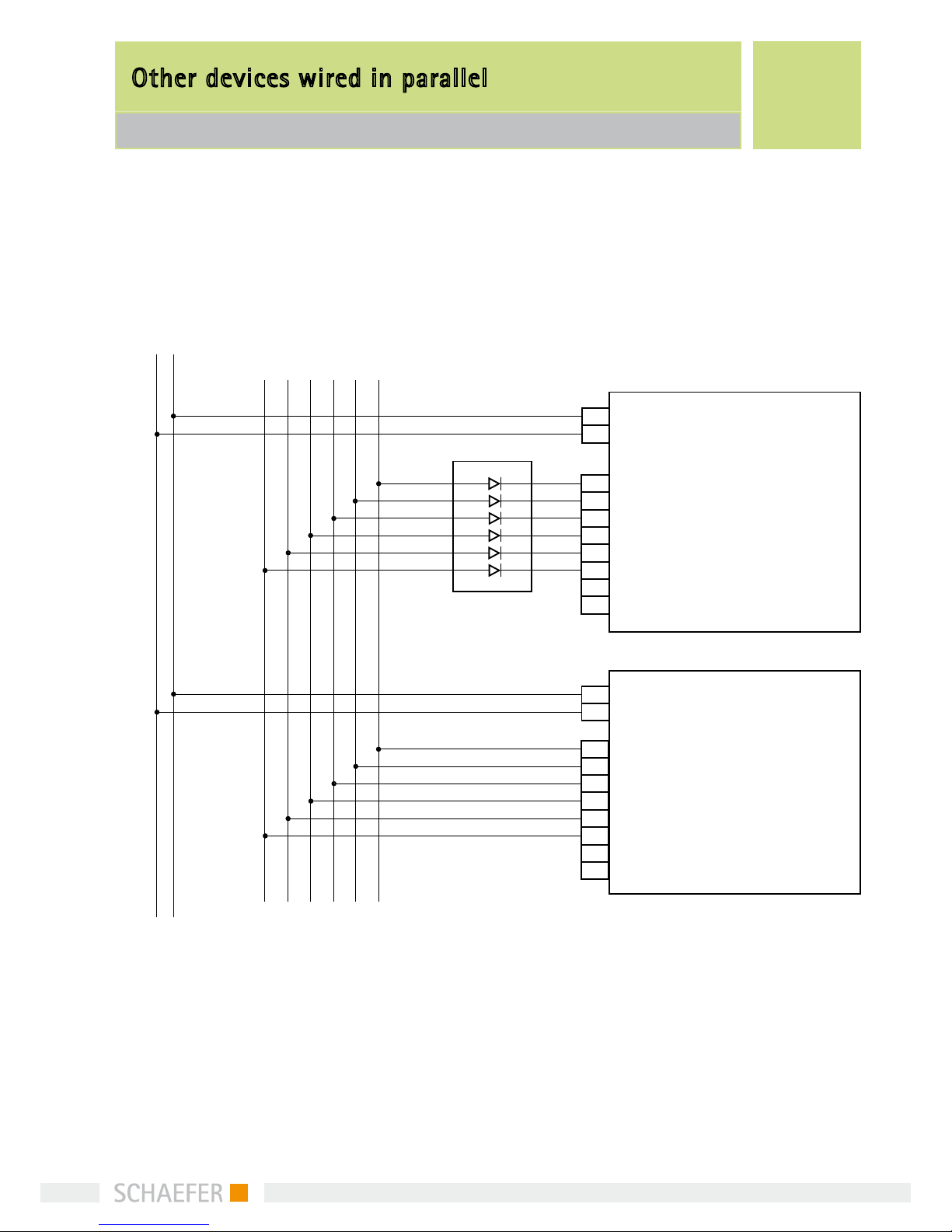
10 Other devices wired in parallel
Ifotherdevices(e.g.SYN42,SM84;DMD)arewired
in parallel to the LCD 240, an uncoupling PCB has to
be inserted into the signal lines.
common anode
+
-
SYN42 ,SM84
DMD
+
-
LCD 240 -2 HP -2 HPC -2 VP
or
VEBUS A1
GND
uncoupling PCB
+UB
signal lines
(floors, direction, ....)
If more than 6 signal lines are used, a second uncou-
pling PCB is needed.
13
Other devices wired in parallel
common cathode
+
-
SYN42 ,SM84
DMD
+
-
LCD 240 -2 HP -2 HPC -2 VP
or
VEBUS A1
GND
uncoupling PCB
+UB
signal lines
(floors, direction, ....)
14
11.1 Description | 11.2 Features
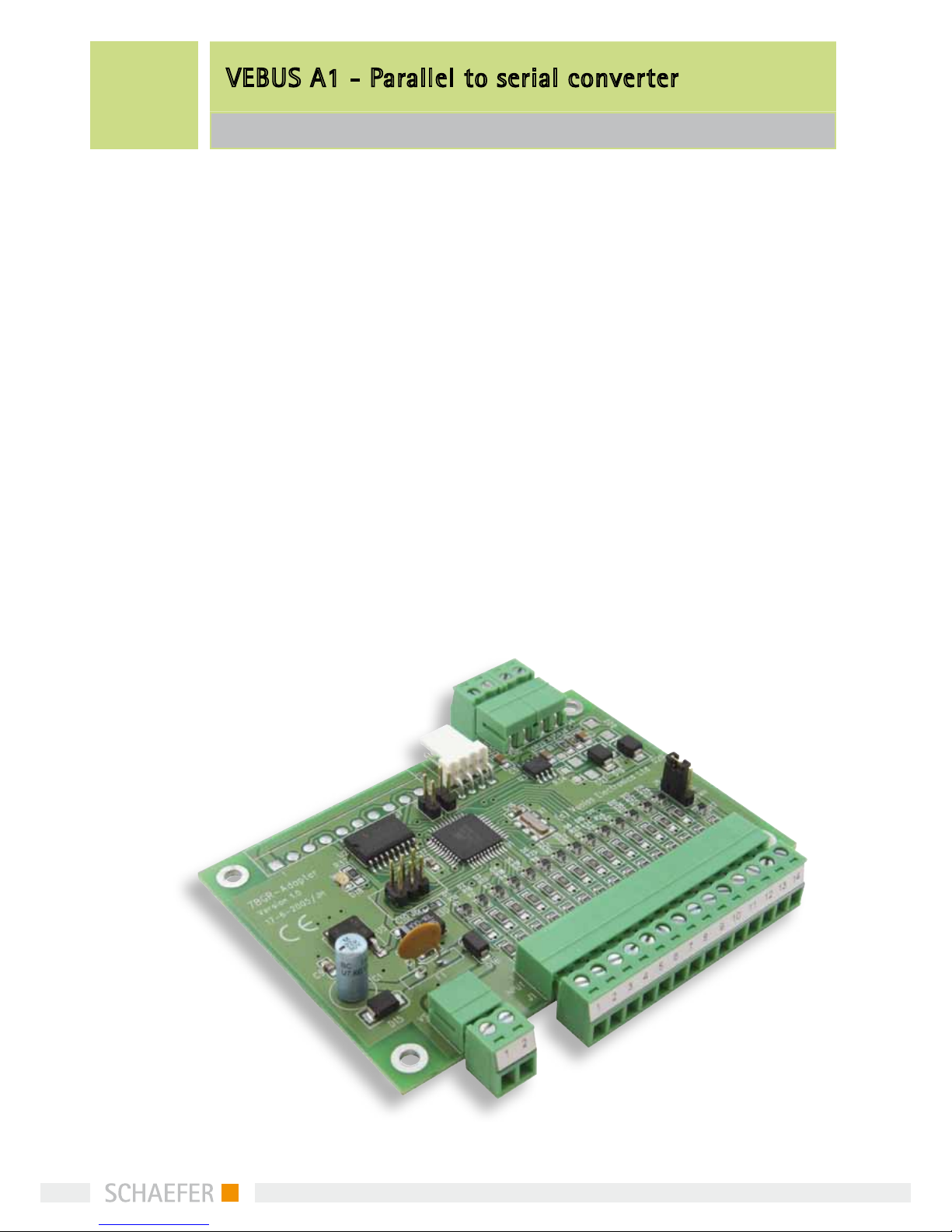
VEBUS A1 - Parallel to serial converter
11 VEBUS A1 -
Parallel to serial converter
11.1 Description
VEBUS A1 is a general purpose converter card for
different bus interfaces. It is intended for lift appli-
cations. It converts typical binary parallel control to
RS-485 compatible serial control.
10.2 Features
Intended for lift applications Maximum number of
floors is 32 Converts parallel input to serial output
(VEBUS) VEBUS is a RS-485 compatible serial interface
designed for lift applications

15
11.3 System block diagram
VEBUS A1 – Parallel to serial converter
11.3 System block diagram
LCD 240
4
Aufzugssteuerung
Dual/Gray
Spannungsversorgung
Schacht
I 3^
I 3^
I 3^
^I 3
I 3^
Kabine
Spannungsversorgung / BUS
LCD 240
/ 4
VEBUS A1
I 3
^
I 3
^
I 3
^
I 3
^
I 3
^
I 3
^
Kabine
Schacht
Spannungsversorgung / BUS
Dual/Gray
Spannungsversorgung
VEBUS A1
Aufzugssteuerung
16
VEBUS A1 - Parallel zu serial converter
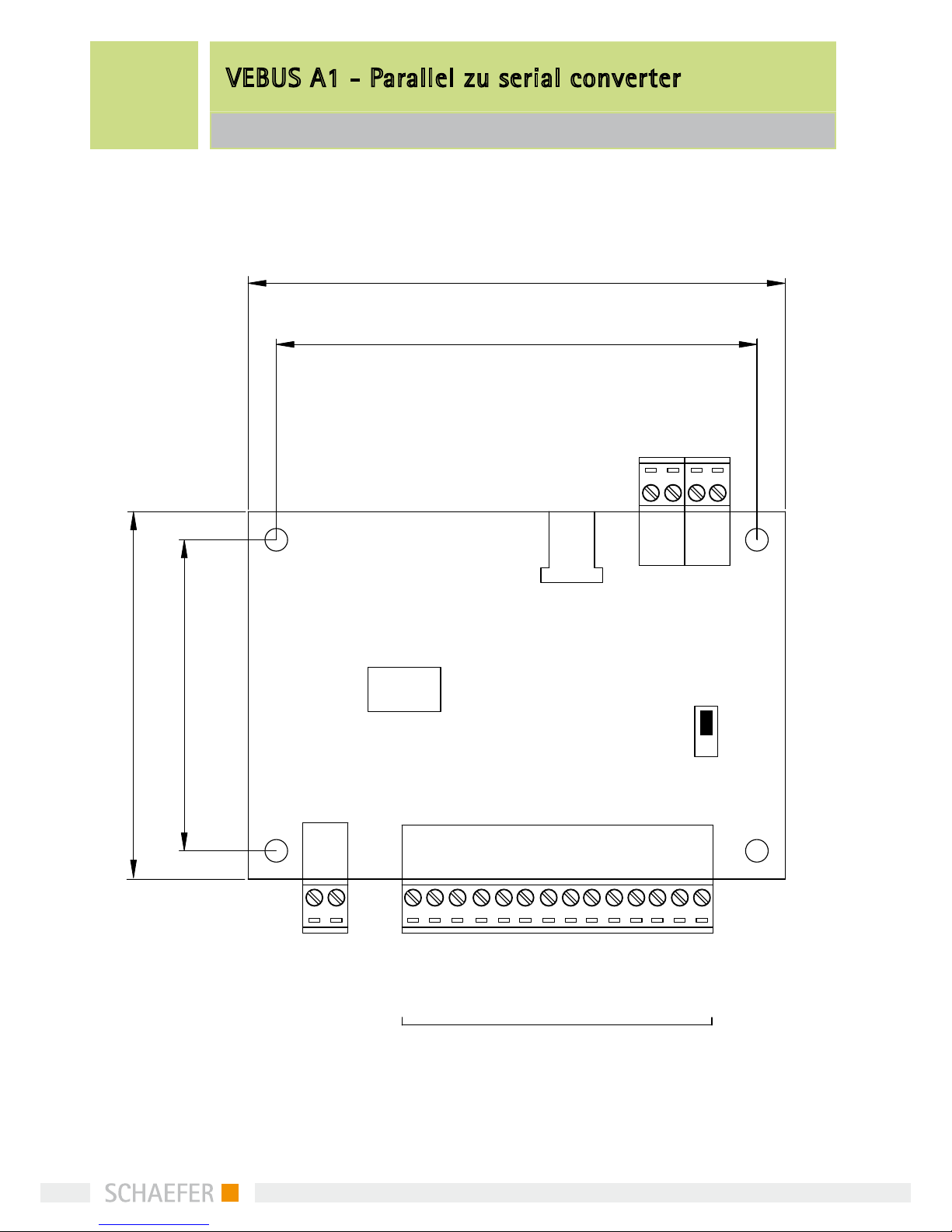
11.4 connection
11.4 connection
95 mm
85 mm
65 mm
55 mm
J7
OUTPUT (DUAL/GRAY) OUTPUT
J3 J4
J9
J6
Prog.
J2 J1
Adr.0
V in
Gnd
UP
PULL
DOWN
J5
Adr.1
Adr.2
Adr.3
Adr.4
Adr.5/Fahrt
Sondertext 1
Sondertext 2
Sondertext 3
Sondertext 4
Pfeil auf
Pfeil ab
V out
Gnd
V out
B
A
GND
Adr.1
Adr.2
Adr.3
Adr.4
Adr.5
InD1
InD2
Adr.0
PARALLEL INPUT
INPUT 12-30 V DC
OUTPUT
55
65
85
95
Gnd
V out
B
A
Adr.0
V in
Gnd
Adr.1
Adr.2
Adr.3
Adr.4
Adr.5/Fahrt
Sondertext 1
Sondertext 2
Sondertext 3
Sondertext 4
Gong auf
Gong ab
Pfeil auf
Pfeil ab
PARALLEL INPUT
INPUT 12 ... 30 V DC
UP
PULL
DOWN
Prog.
17
VEBUS A1 – Parallel to serial converter
11.4 connection
11.4.1 Electrical adjustment
Power supply input
Operating voltage range, 12…30 VDC
(max. 5% ripple voltage)
Current consumption, 33 mA @ 24 VDC
(no load)
Parallel control interface (J1)
Internal pull-down or pull-up resistors
depending on jumper setting
• Jumperissettomatchcontrolsignalpolarity
(optional)
• Pull-down/-upresistance:10k
• Inputvoltagerange:0–30VDC
- Power supply input:
- Logic 0:0-1 VDC
- Logic 1:10-30 VDC
Symbol control inputs:
• 4inputsforthesymbolindicationscontrol
• 2inputsforarrowdirectioncontrol
(ARR-UP, ARR-DOWN)
• 1inputfortravellingsignal
VEBUS serial communication interface (optional)
RS-485 compatible bus connections
Protocol is develop and optimized for lift
applications
Speed: 38400 bps
Feed through connector for supply voltage (J3),
Max. load 3A

18
11.5 Function | 11.6 Electrical adjustment | 11.7 Size a. environment
VEBUS A1 – Parallel to serial converter
11.5 Function
Device reads its parallel input every 100 ms. If there
is a change in the parallel input, device immediately
sends the serial control packet to V EBUS interface.
Device also sends the serial control packet every 500
ms, if there are no changes in the parallel input.
10.6 Electrical adjustment
Jumper J5 should be set tomatch the input signal
polarity. When changing jumper position, first dis-
connect the device frompower supply, then change
the jumper position and after that connect the de-
vice back to power supply. This is because the device
automatically adapts to different input polarities by
reading the jumper position tomemory when power
is switched on.
10.7 Size and environment
Size (+additional space for connectors)
Physical dimensions: 95 mm x 65 mm x 18 mm
Tolerances: ± 0,3 mm
Operation environment
Temperature: 0–70° C
Dry environment, RH: < 85% (no condensation)
Not to be used in wet, moist or dusty
environment

19
Memo
This manual suits for next models
6
Table of contents


