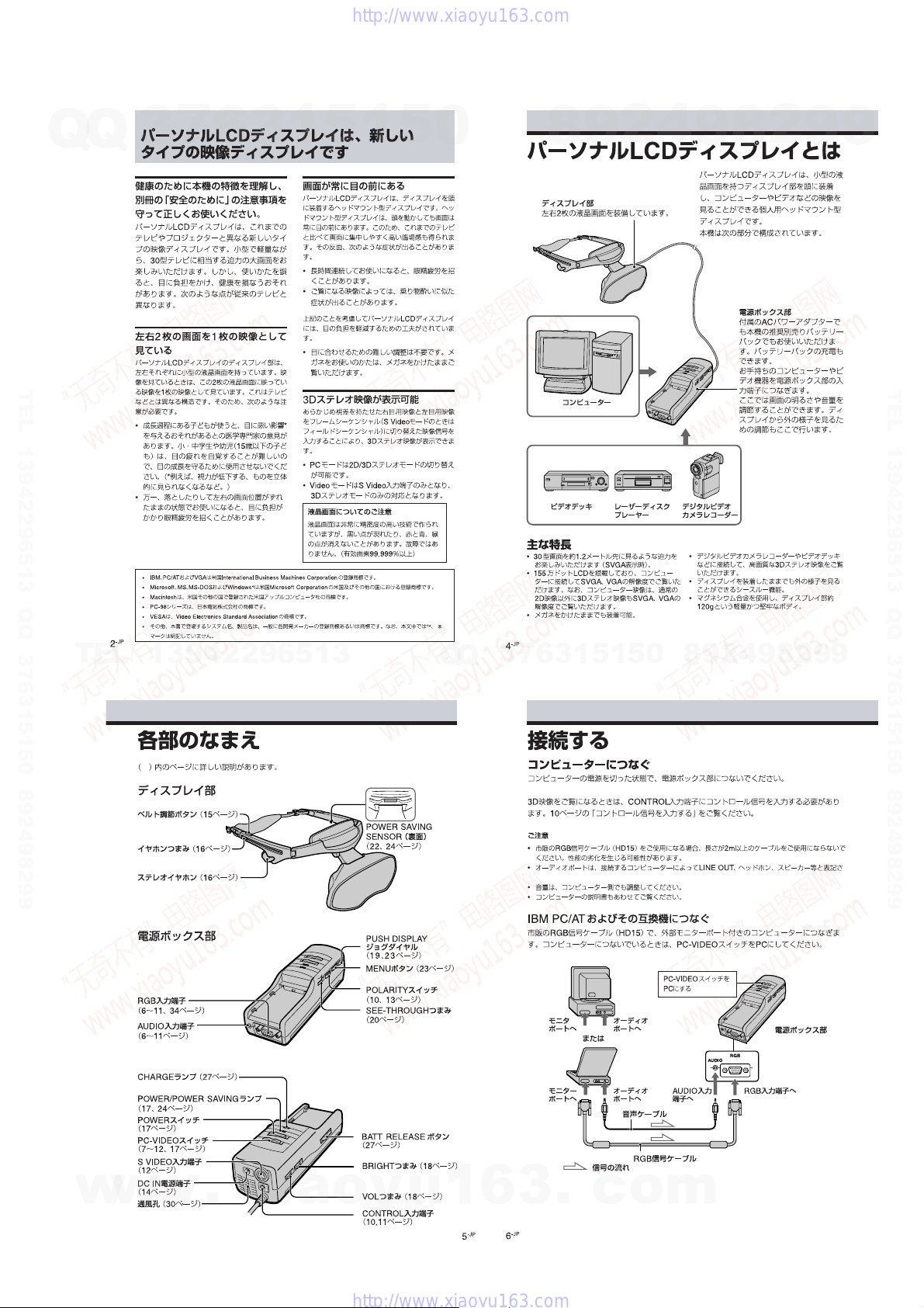
Sony LDI-D100B User manual

SERVICE MANUAL
SPECIFICATIONS
パーソナルLCDディスプレイ
PERSONAL LCD DISPLAY
LDI-D100B
9-928-133-01
– Continued on next page –
NTSC Model
Powersupply
AC poweradapter: AC-PLM3
100-240 V AC, 50/60 Hz, 16 W
Output voltage 8.4 V, 1.6 A
Battery pack: NP-F550/F750/F950
(not supplied)
Powerconsumption
10 W (approx., PC mode)
12 W (approx., VIDEO mode)
Operating temperature
41°F to 95°F (5°C to 35°C)
Storage temperature
14°F to 140°F (–10°C to 60°C)
Dimensions
Displayunit:
Approx.5
7
/
8
×1
15
/
16
×3
1
/
2
inches
(Approx.149 ×48 ×86 mm)
(w/h/d folded)
Power supplybox:
Approx.2
1
/
4
×1
7
/
8
×6
3
/
8
inches
(Approx.54 ×47 ×160 mm)
(w/h/d)
not including projecting parts and
controls
Mass
Displayunit:Approx.4.2 oz. (120 g)
Power supply box: Approx.9.2 oz. (260 g)
Videosignal
NTSC color, CCIR standards
VIDEO Input
PC mode
RGB signal: HD15
PinAssignment
5 4 3 2 1
876
15 14 13 12 11
10 9
PinNo. Signal
1 R (Red)
2 G (Green)
3 B (Blue)
4
5 GND
6 R (Red) GND
7 G (Green) GND
8 B (Blue) GND
9
10 GND
11 GND
12 –
–
–
13 SYNC (Horizontal)
14 SYNC (Vertical)
15 –
注:“4.ブロックダイヤクラム”は,別冊(9-928-133-31)
に記載されています。
NOTE :“SECTION 4 DIAGRAMS” is provided in the
separate manual (9-928-133-31).
w
w
w
.
x
i
a
o
y
u
1
6
3
.
c
o
m
Q
Q
3
7
6
3
1
5
1
5
0
9
9
2
8
9
4
2
9
8
T
E
L
1
3
9
4
2
2
9
6
5
1
3
9
9
2
8
9
4
2
9
8
0
5
1
5
1
3
6
7
3
Q
Q
TEL 13942296513 QQ 376315150 892498299
http://www.xiaoyu163.com

– 2 –
1. 注意事項をお守りください。
サービスのとき特に注意を要する個所については,キャ
ビネット,シャーシ,部品などにラベルや捺印で注意事
項を表示しています。これらの注意書き及び取扱説明書
等の注意事項を必ずお守り下さい。
2. 指定部品のご使用を
セットの部品は難燃性や耐電圧など安全上の特性を持っ
たものとなっています。従って交換部品は,使用されて
いたものと同じ特性の部品を使用して下さい。特に回路
図,部品表に0印で指定されている安全上重要な部品は
必ず指定のものをご使用下さい。
3. 部品の取付けや配線の引きまわしはもとどおりに
安全上,チューブやテープなどの絶縁材料を使用した
り,プリント基板から浮かして取付けた部品がありま
す。また内部配線は引きまわしやクランパによって発熱
部品や高圧部品に接近しないよう配慮されていますの
で,これらは必ずもとどおりにして下さい。
4. サービス後は安全点検を
サービスのために取外したネジ,部品,配線がもとどお
りになっているか,またサービスした個所の周辺を劣化
させてしまったところがないかなどを点検し,安全性が
確保されていることを確認して下さい。
5. チップ部品交換時の注意
•取外した部品は再使用しないで下さい。
•タンタルコンデンサのマイナス側は熱に弱いため交換
時は注意して下さい。
6. フレキシブルプリント基板の取扱いについて
•コテ先温度を270℃前後にして行なって下さい。
•同一パターンに何度もコテ先を当てないで下さい。
(3回以内)
•パターンに力が加わらないよう注意して下さい。
7. 多層プリント基板の取扱いについて
できるだけプリント基板はねじれ,たわみのないように
取扱いして下さい。フラットパッケージIC等のハンダ
付けが取れることがあります。
サービス,点検時には次のことにご注意下さい。
Notes on chip component replacement
• Never reuse a disconnected chip component.
• Notice that the minus side of a tantalum capacitor may be dam-
aged by heat.
Flexible Circuit Board Repairing
• Keep the temperature of the soldering iron around 270 ˚C dur-
ing repairing.
• Do not touch the soldering iron on the same conductor of the
circuit board (within 3 times).
• Be careful not to apply force on theconductorwhensoldering
orunsoldering.
SAFETY-RELATED COMPONENT WARNING!!
COMPONENTS IDENTIFIED BY MARK 0OR DOTTED
LINE WITH MARK 0ON THE SCHEMATIC DIAGRAMS
AND IN THE PARTS LIST ARE CRITICAL TO SAFE
OPERATION. REPLACE THESE COMPONENTS WITH
SONY PARTS WHOSE PART NUMBERS APPEAR AS
SHOWN IN THIS MANUAL OR IN SUPPLEMENTS PUB-
LISHED BY SONY.
ATTENTION AU COMPOSANT AYANT RAPPORT
À LA SÉCURITÉ!
LES COMPOSANTS IDENTIFIÉS PAR UNE MARQUE 0
SUR LES DIAGRAMMES SCHÉMATIQUES ET LA LISTE
DES PIÈCES SONT CRITIQUES POUR LA SÉCURITÉ
DE FONCTIONNEMENT. NE REMPLACER CES COM-
POSANTS QUE PAR DES PIÈCES SONY DONT LES
NUMÉROS SONT DONNÉS DANS CE MANUEL OU
DANS LES SUPPLÉMENTS PUBLIÉS PAR SONY.
VIDEO mode
S VIDEO input:4-pin miniDIN
Y: 1 Vp-p, 75 ohms, unbalanced, sync
negative
C: 0.286 Vp-p,75 ohms, unbalanced,
sync negative
AUDIO input
Stereo miniplug
CONTROL input connector(used in PC
mode only)
Special type stereo miniplug
Screen resolution
Horizontal:832 dots (max.)
Vertical: 624 lines (max.)
Supplied accessory
AC poweradapter: AC-PLM3(1)
Power cords (2)
Design and specifications are subject to
change without notice.
w
w
w
.
x
i
a
o
y
u
1
6
3
.
c
o
m
Q
Q
3
7
6
3
1
5
1
5
0
9
9
2
8
9
4
2
9
8
T
E
L
1
3
9
4
2
2
9
6
5
1
3
9
9
2
8
9
4
2
9
8
0
5
1
5
1
3
6
7
3
Q
Q
TEL 13942296513 QQ 376315150 892498299
http://www.xiaoyu163.com

– 3 –
1. 概要
GENERAL
パーソナルLCDディスプレイは,
新しいタイプの映像ディスプレイです ................. 1-1
パーソナルLCD ディスプレイとは........................ 1-1
各部のなまえ.............................................................. 1-1
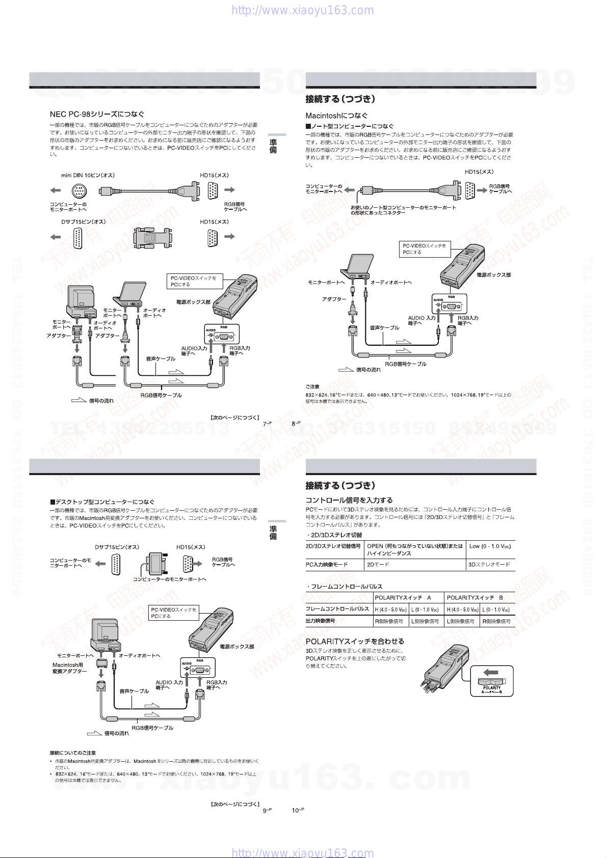
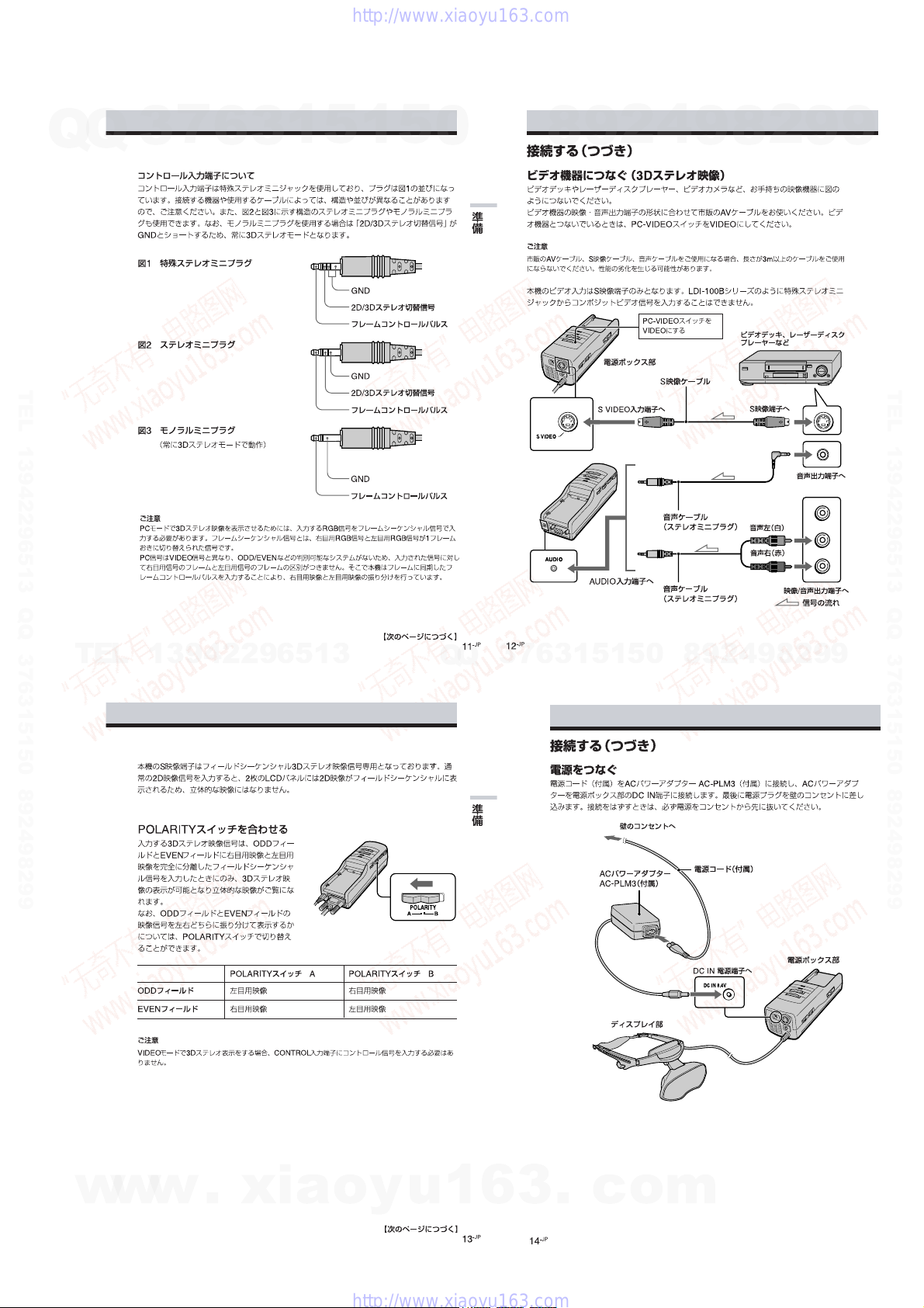
接続する...................................................................... 1-1
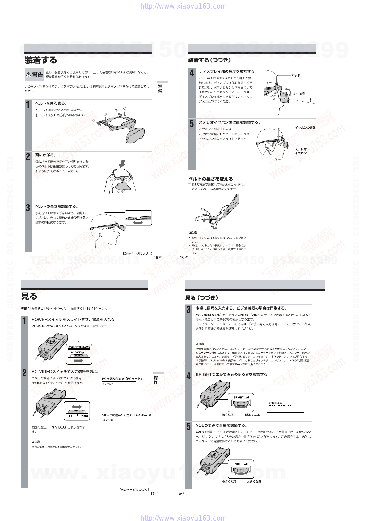
装着する...................................................................... 1-4
見る .............................................................................. 1-4
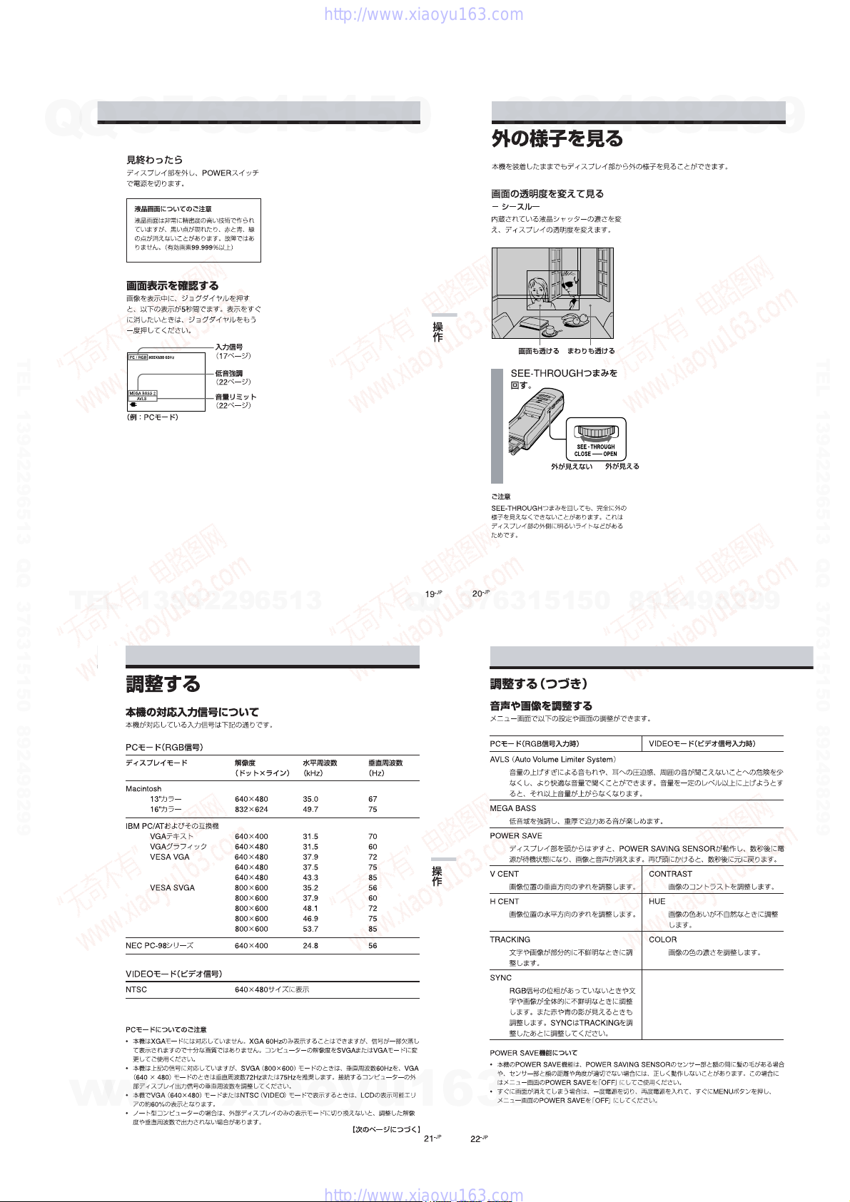
外の様子を見る.......................................................... 1-5
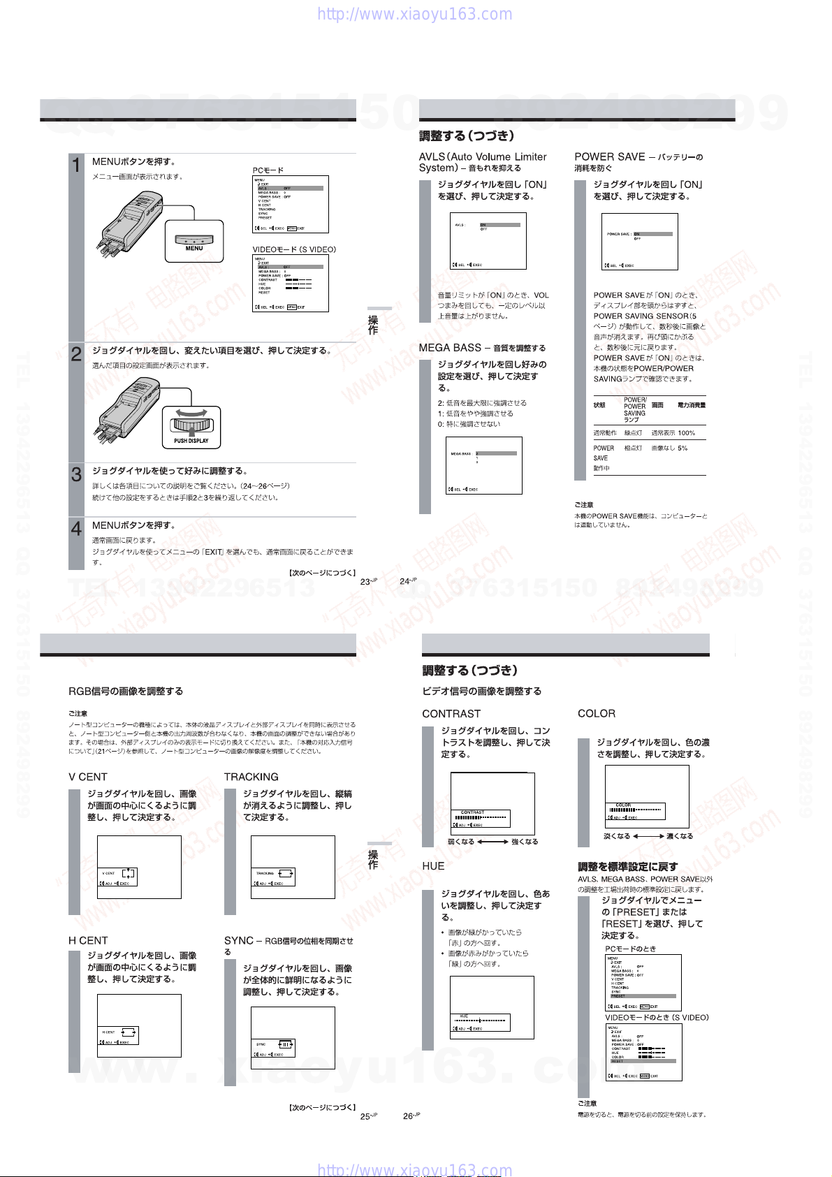
調整する...................................................................... 1-5
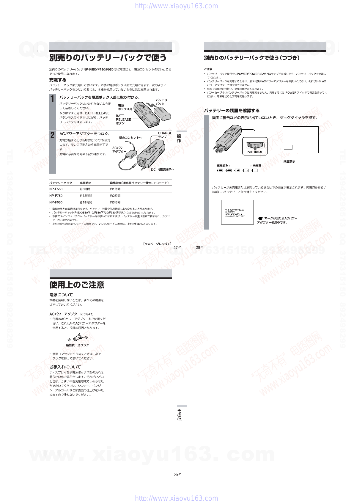
別売りのバッテリーパックで使う.......................... 1-7
使用上のご注意.......................................................... 1-7
The Personal LCD Display is
a Brand-new Concept in Visual Display ..................... 1-8
About the Personal LCD Display ................................ 1-8
Locating the Parts and Controls .................................. 1-8
Connecting the Personal LCD Display ....................... 1-9
Wearing the Personal LCD Display ............................ 1-11
Using the Personal LCD Display ................................ 1-11
Viewing the Surrounding Environment ...................... 1-12
Adjusting the Sound and Picture ................................. 1-12
Using the Optional Battery Pack ................................. 1-14
Precautions ................................................................... 1-14
2. 外し方
DISASSEMBLY ...................................................... 2-1
3. 電気調整 .................................................................... 3-1
ELECTRICAL ADJUSTMENTS...................... 3-16
4. ダイヤグラム(別冊:9-928-133-31)
DIAGRAMS (Separete Volume: 9-928-133-31)
4-1. Block Diagram – AUDIO/VIDEO Section –............. 4-1
4-2. Block Diagram
– A/D, D/A, OSD, SYNC Section –............................ 4-5
4-3. Block Diagram
– GAMMA CONTROL/LCD DRIVE Section – ........ 4-7
4-4. Block Diagram
– MODE CONTROL/SENSOR/LCS Section – ......... 4-9
4-5. Block Diagram – POWER SUPPLY Section – ......... 4-11
4-6 プリント図,回路図共通ノート
Note for Printed Wiring Boards and
Schematic Diagrams .................................................... 4-14
4-7. Printed Wiring Board – JK-136 (H) Board – ............. 4-15
4-8. Schematic Diagram – JK-136 (H) Board – ................. 4-16
4-9. Schematic Diagram – YC-148 (H) Board (1/3) – ....... 4-17
4-10. Schematic Diagram – YC-148 (H) Board (2/3) – ....... 4-19
4-11. Schematic Diagram – YC-148 (H) Board (3/3) – ....... 4-24
4-12. Printed Wiring Board – YC-148 (H) Board – ............ 4-27
4-13. Printed Wiring Board – MA-324 (H) Board – ........... 4-30
4-14. Schematic Diagram – MA-324 (H) Board (1/7) – ...... 4-33
4-15. Schematic Diagram – MA-324 (H) Board (2/7) – ...... 4-37
4-16. Schematic Diagram – MA-324 (H) Board (3/7) – ...... 4-41
4-17. Schematic Diagram – MA-324 (H) Board (4/7) – ...... 4-44
4-18. Schematic Diagram – MA-324 (H) Board (5/7) – ...... 4-47
4-19. Schematic Diagram – MA-324 (H) Board (6/7) – ...... 4-51
4-20. Schematic Diagram – MA-324 (H) Board (7/7) – ...... 4-53
4-21. Printed Wiring Board – LC-61 (F) Board – ............... 4-55
4-22. Schematic Diagram – LC-61 (F) Board – ................... 4-57
4-23. Printed Wiring Board – SW-306 (H) Board – ........... 4-60
4-24. Schematic Diagram – SW-306 (H) Board – ............... 4-63
4-25. Printed Wiring Board – DD-107 (H) Board –............ 4-65
4-26. Schematic Diagram – DD-107 (H) Board –................ 4-67
5. ICダイヤグラム
IC DIAGRAMS
5-1. IC Block Diagrams ...................................................... 5-1
5-2. IC Pin Function Description ........................................ 5-11
6. 分解図
EXPLODED VIEWS............................................. 6-1
7. 電気部品表
ELECTRICAL PARTS LIST ............................ 7-1
TABLE OF CONTENTS
w
w
w
.
x
i
a
o
y
u
1
6
3
.
c
o
m
Q
Q
3
7
6
3
1
5
1
5
0
9
9
2
8
9
4
2
9
8
T
E
L
1
3
9
4
2
2
9
6
5
1
3
9
9
2
8
9
4
2
9
8
0
5
1
5
1
3
6
7
3
Q
Q
TEL 13942296513 QQ 376315150 892498299
http://www.xiaoyu163.com

1-8
4
-US
The Personal LCD Display isa brand-new
concept in visual display
Noteon theLCD (Liquid Crystal
Display)
The LCD screen is made withhigh-
precision technology. However, black
points or bright points of light (red, blue,
or green) may appear constantly on the
LCD screen. This is not a malfunction.
(Effective dots: more than 99.999%)
Congratulations on your purchase of the
Sony Personal LCD Display. The Personal
LCD Displayusing current technology in
small, lightweight visual displays, provides
a television viewing experience similarto
watching a 30-inch television from a
distance of approximately4 feet in SVGA
mode. (Viewing experience may differ
according to individual perception.)
The Personal LCD Display creates an image
through two separate liquid crystal
displays, in close proximity to your eyes.
To insure your safe use of the Personal LCD
Display, please become familiar with its
basic operations, including proper fitting
instructions,and be aware of any symptoms
of eye fatigue or other discomfort you may
experience.
3D Stereoscopic pictures
You can enjoy 3D (3-dimensional)
stereoscopic pictures by using video signals
that are already processed to compensate
for parallax. The Personal LCD Display
switches these optimizedpictures for each
eye using a frame sequential method (field
sequential in the S-Video input) to display
the 3D stereoscopic pictures.
• In PC mode, you can select the display
mode between 2D (normal pictures) and
3D stereoscopic.
• In Video mode, only the signal inputto
the S-Video connector is available, and
the displaymode is fixedto 3D
stereoscopic mode.
•IBM PC/ATand VGAare registered trademarks of IBM Corporationof the U.S.A.
•Microsoft, MS, MS-DOS and Windows
are registered trademarks of MicrosoftCorporationin the
UnitedStates and other countries.
•Macintosh is a trademark licensed to Apple Computer, Inc., registered in the U.S.A. and other
countries.
•VESA is a trademark of Video Electronics Standard Association.
•Allother productnames mentioned herein may be the trademarks or registered trademarks of
their respective companies. Furthermore, “”and “” are not mentioned in each case in this
manual.
WARNING
YOUR FAILURE TO FOLLOW THESE
OPERATING INSTRUCTIONS ANDTHE
SUPPLIED IMPORTANTSAFEGUARDS
MAY RESULT IN EYE FATIGUE, EYE
IMPAIRMENT,OR OTHER EYE INJURY,
PROPERTY DAMAGE,OR DEATH.
WARNING
THIS PRODUCT SHOULD NOT BE USED
BY CHILDRENAGE 15 OR YOUNGER.
THE EYES OF CHILDRENARE STILL
DEVELOPING ANDMAY BE ADVERSELY
AFFECTED FROM USE OF THISPRODUCT.
SECTION 1
GENERAL
6
-US
Features
• A powerful,big screen experience comparable to
watchinga 30-inch screen fromapproximately4
feet (1.2 m) away (SVGA mode).
• You can connect the Personal LCD Display,
which is equipped with two 1.55 million dot
LCDs, to your PC to see the screen of the PC in
SVGA or VGA screen mode.You can also enjoy
3D stereoscopic pictures, aswellas 2D pictures,
in SVGA or VGA screen mode.
About thePersonal LCD Display
Caution:The screen is always right in front of you.
The Personal LCD Display is a head-mounted display. With this type of display, the screen is
always in front of you even when you move your head. Because of this feature, you can
concentrate on the screen more easily compared with ordinary TVs, and you have a sense of
being in the action.
• It is easy to adjust the Personal LCD Displayto yourface and eyes. You can use the display
unit even while wearing glasses.
The Personal LCD Display consists of the following items:
The display unit is equipped with two small (left and right) LCDs.
PersonalComputer
VCR Laser disc player Camcorder
Powersupplybox
You can supplypower using the
suppliedAC power adapter or the
optionalSony rechargeable battery
pack.
When using withthe Personal LCD
Display, connect yourvideo
equipment or PC to the connector
on the power supplybox.
You can adjust the sound volume.
You can also use the SEE-
THROUGHcontrol in order to see
the surrounding environment.
• You can enjoy high quality 3D stereoscopic
pictures by connecting to video equipment such
as a digital camera recorder or a VCR.
• The see-through function allowsyou to see the
surrounding environment while wearing the
Personal LCD Display.
• You can use the Personal LCD Display while
wearing glasses.
• Solid and lightweight components made of
magnesium alloy, with the display unit
weighing about 5.3 oz. (120 g).
Display unit
7-US
Getting Started
Locatingthe parts and controls
Refer to the pages indicated in parentheses ( ) for details.
POWER SAVING SENSOR
(innerside)(24, 26)
Strap release button (17)
Earphoneslide button
(18)
Stereo earphone (18)
Display unit
continued
8-US
Powersupplybox
MENU button (25)
CONTROL connector (12, 13)
BRIGHT control(20)
VOL control (20)
PUSH DISPLAY jogdial(21, 25)
POLARITYswitch (12, 15)
SEE-THROUGH control(22)
RGB connector
(9 to11, 36)
POWER/POWER SAVING
lamp(19, 26)
POWER switch(19)
PC-VIDEO switch
(9 to14, 19)
S VIDEO connector
(14)
DC IN connector
(16)
Ventilation openings(33)
BATT RELEASE button (29)
CHARGE lamp(29)
Locatingthe partsand controls(continued)
AUDIO connector
(9 to11)
w
w
w
.
x
i
a
o
y
u
1
6
3
.
c
o
m
Q
Q
3
7
6
3
1
5
1
5
0
9
9
2
8
9
4
2
9
8
T
E
L
1
3
9
4
2
2
9
6
5
1
3
9
9
2
8
9
4
2
9
8
0
5
1
5
1
3
6
7
3
Q
Q
TEL 13942296513 QQ 376315150 892498299
http://www.xiaoyu163.com

1-9
9
-US
Getting Started
AUDIO RGB
Connecting thePersonal LCD Display
Connecting aPC
Be sure toturn off your PC before connecting the power supply box.
To enjoy 3D stereoscopic pictures, the control signal mustbe supplied to the CONTROL
connector. See “Supplying the control signal”in page 12.
Notes
•Do not use an RGB signal cable (HD15) whichis 6.5 feet (2 m) or longer. The performance may be
reduced.
•Refer to the instruction manual supplied with your PC as well.
•Depending on your computer, the audio port may be indicated as LINE OUT, headphone, speaker,
etc.
•Adjustsound volume on the computer.
Connecting other IBM compatible PCs
Connect the Personal LCD Display to your PC using a commercially available RGB signal
(HD15) cable. When youconnect the Personal LCD Display to your PC, set the PC-VIDEO
switch on the power supply box to “PC.”
to monitor port to audio port
or
tomonitor port to audio port
: Signal flow
Audio cable
RGB signal cable
toAUDIO
connector to RGB connector
Powersupply box
Set the PC-VIDEO switch
to“PC.”
continued
10
-US
AUDIO RGB
Connecting the Personal LCD Display(continued)
Connecting a Macintosh Powerbook
Depending on the model, you may need to use a commercially available adapter to connect a
commercially available RGB signal cable as shown below. When you connect the Personal LCD
Display to your Powerbook, set the PC-VIDEO switch on the power supply box to “PC.”
VGA type connector
(HD15, female)
Connector should match themonitor
port of your Powerbook model.
tomonitor
port of
Powerbook
toRGB
signalcable
<
Set the PC-VIDEO switch
to“PC.”
to monitor port to audio port
: Signal flow
RGB signal cable
toAUDIO
connector to RGB connector
Audio cable
Adapter
Power supply box
Noteonconnection
Set the displaysetting to 16-inch display mode (832 ×624) or 13-inch display mode (640×480).
The Personal LCD Display cannot display images with the 19-inch display mode (1024 ×768) setting or
more.
,
11-US
Getting Started
AUDIO RGB
Connectinga Macintosh (desktop models)
Depending on the model, youmay need to use a commercially available Macintosh adapter to
connect a commercially available RGB signal cable as shown below. When you connect the
Personal LCDDisplay to yourMacintosh,set the PC-VIDEO switchon the power supply box to
“PC.”
Set the PC-VIDEO switch
to“PC.”
to monitor port to audio port
: Signal flow RGB signal cable
toAUDIO
connector to RGB connector
Audio cable
VGA typeconnector
(HD15, female)
tomonitor
port
Powersupply box
to monitor port
ofMacintosh to RGB signalcable
Macintosh
adapter
Noteson connection
• Usea commerciallyavailable Macintosh adapter whichsuppors the models after the Macintosh II
series.
• Set the display setting to 16-inch display mode (832 ×624) or 13-inch displaymode (640×480). The
Personal LCD Displaycannot displayimages withthe 19-inch display mode (1024 ×768) setting or
more.
<,
(D-Sub15-pin,
male)
continued
12-US
Connecting thePersonal LCD Display(continued)
Supplyingthecontrolsignal
To enjoy 3D stereoscopic pictures in PC mode, the controlsignal must be suppliedto the
CONTROLconnector. There are twosignals; “2D/3D stereoscopic control signal”and “frame
controlpulse.”
• 2D/3D stereoscopic control signal
2D/3D stereoscopic OPEN (No connection)or high impedance Low(0 - 1.0 V DC)
control signal
PC mode 2D mode 3D stereoscopic mode
• Framecontrolpulse
POLARITY switch A POLARITY switch B
Frame control pulse H (4.0 - 5.0 V DC) L (0 - 1.0 V DC) H (4.0 - 5.0 VDC) L (0 - 1.0 VDC)
Output video signal
Right side video signal Left side video signal Left side video signal Right side video signal
Setting the POLARITY switch
To display the 3D stereoscopic pictures
correctly, set the POLARITYswitch
according to the table above.
AB
POLARITY
w
w
w
.
x
i
a
o
y
u
1
6
3
.
c
o
m
Q
Q
3
7
6
3
1
5
1
5
0
9
9
2
8
9
4
2
9
8
T
E
L
1
3
9
4
2
2
9
6
5
1
3
9
9
2
8
9
4
2
9
8
0
5
1
5
1
3
6
7
3
Q
Q
TEL 13942296513 QQ 376315150 892498299
http://www.xiaoyu163.com

1-10
13
GettingStarted
Notes on CONTROL connector
The CONTROL connector uses the special type of the stereo miniplug shown in Figure 1 below.
Note that the connector of the video equipment or video cables may differ from the CONTROL
terminal.
Inaddition to the special miniplug,you can also use a stereo miniplug or monaural miniplug
shown in Figures 2 and 3. If you use the monaural miniplug,note that the display mode will be
fixed to 3D stereoscopic mode because the GND and 2D/3D stereoscopic control signals are not
separated.
Figure1 Special type stereo miniplug
Figure2 Stereo miniplug
Figure3 Monaural miniplug
(Fixed to 3D stereoscopic mode)
Note
When you want to display3D stereoscopic pictures in PC mode, the RGB signal in the frame sequential
format must be supplied to the Personal LCD Display. The frame sequential signal switches the frame
pictures for the rightand left eyes alternately for each frame.
Since the RGB signal output fromthe PC does not include frame identification information such as the
ODD/EVEN information of the video signal, the system cannot distinguish which frame is processed
for the right eye and for the left eye. To distinguish frames, the Personal LCD Display uses a frame
control pulse synchronized with the frame transition.
continued
GND
2D/3D stereoscopiccontrol
signal
Framecontrol pulse
GND
2D/3D stereoscopiccontrol
signal
Framecontrolpulse
GND
Frame control pulse
14
-US
SVIDEO
AUDIO
VCR, Laser disc player,etc.
S-video cable
Audio cable
(stereominiplug)
Power supply box
Audio R (red)
AudioL (white)
to audio/video outputs
toS VIDEO connector toS-video output
to audio output
Set the PC-VIDEO switch
to“VIDEO.”
Audio cable
(stereo miniplug) : Signal flow
Connecting video equipment (3D stereoscopicpicture)
Connect a VCR, laser disc player, orcamcorder to the power supply box using a commercially
available audio/video cable as shown below. When you connect the Personal LCD Display to
the video equipment, set the PC-VIDEO switch on the power supply box to “VIDEO.”
Note
Do not use audio, audio/video, or S-video connecting cables, which are 9.8 feet (3 m) or longer. The
performance may be reduced.
You can use only the S-Video connector to enjoy the 3D stereoscopic picture from the video
equipment.You cannot input the composite video signal to the Personal LCD Display by using
the special type stereo miniplug, likewise with the LDI-100B series.
Connecting the Personal LCD Display(continued)
toAUDIO connector
The S-Video connector of the Personal LCD Display is designed only for supplying the field
sequential 3D stereoscopic picture signal. If a normal 2D video signal is supplied,the Personal
LCD Display simply displays normal 2D pictures on each LCD panel in the field sequential
method, but 3D stereoscopic pictures will not appear.
15
-US
Getting Started
Setting the POLARITY switch
You can enjoy 3D stereoscopic pictures only
when the following signal is supplied: field
sequential signals that completely separate
the pictures for the right and left eyes using
the ODDand EVEN sequential fields.
You can also set which field is for right (or
left)eye by setting the POLARITY switch.
POLARITY switch A POLARITY switch B
ODD field For the left eye For the right eye
EVEN field For the right eye For the left eye
Note
To enjoy 3D stereoscopic pictures in VIDEO mode, you do not have to supply the control signal to the
CONTROL connector.
continued
AB
POLARITY
16-US
DC IN 8.4V
Connecting the power source
Connect the AC power adapter AC-PLM3 (supplied) to the DC IN connector on the power
supply box. Then, connect the AC power cord (supplied) to the AC power adapter and to a wall
outlet. Do not connect the power source until all other connections are complete.
Displayunit
AC power adapter
AC-PLM3 (supplied)
towalloutlet
Power supply box
toDC IN connector
AC power cord(supplied)
Connecting the Personal LCD Display(continued)
w
w
w
.
x
i
a
o
y
u
1
6
3
.
c
o
m
Q
Q
3
7
6
3
1
5
1
5
0
9
9
2
8
9
4
2
9
8
T
E
L
1
3
9
4
2
2
9
6
5
1
3
9
9
2
8
9
4
2
9
8
0
5
1
5
1
3
6
7
3
Q
Q
TEL 13942296513 QQ 376315150 892498299
http://www.xiaoyu163.com

1-11
17
-US
Getting Started
1Loosen the back strap.
1Press and hold the strap release
buttons.
2Then, loosen the back strap in the
direction of the arrows.
2Put on the Personal LCD Display.
Hold the front pad against your
forehead and place the rear strap so itis
fixed firmly around the back of your
head.
3Adjust the strap.
Adjust the strap after putting on the
Personal LCD Display.
Make sure the strap is snug but
comfortable.
2
2
1
1
Wearing thePersonal LCD Display
WARNING
• Failure to properly fit the product each time may result in eye fatigue, eye damage, or loss
of visual functions and may result in accident or injury.
• This product should not be used by children age 15 or younger.
The eyes of children are still developing and may be adversely affected by use of this
product, and it may cause eye fatigue, eye damage, or loss of visual functions.
In addition, this product may not be adjusted to fit a child’s head.
If you normally wear glasses while watching TV, you can use the Personal LCD Display while
wearing glasses.
continued
18
-US
4Adjust the angle of the displayunit.
While holding the front pad against
your forehead, adjust the angle of the
display unit using the two hinges. Move
the display unit close to your eyes at a
slight downward angle. If you wear
glasses, move the display unit as close to
the lenses as possible.
5Adjust the stereo earphones.
Pull the earphones out.
To adjust the slack, reel in the earphone
cord by pressing the slide button in the
direction of the arrow.
Front pad
Stereo
earphones
5 – 10°
Adjusting the back strap
If the strap does not fit properly in step 3,
adjust the strap by changing the belt length.
Earphones
slide button
Wearing the Personal LCD Display(continued)
20-US
Using the Personal LCD Display (continued)
3Input the signal from the connected equipment.
When you connect the PC:
Adjust the screen resolution. For details, see “Signal compatibility”on page 23.
When you display VGA pictures (640 ×480), the picture appears about 60% of the entire
screen.
Notes
• If no picture appears, check the default setting of your PC to output the external RGB signal
from the monitor connector.
• Some PCs do not output external display signal when they turn on, or switch to external
display mode. Change the display mode of your PC, referring to the instruction manual
supplied with your PC.
When you connect the video equipment:
Start playbackon the video equipment connected to the Personal LCD Display.
When you display NTSC video picture, the picture appears about 60% of the entire
screen. For PAL video picture, the picture appears about 84% of the entire screen.
4Adjust the brightness by turningthe BRIGHT control.
5Adjust the sound volume byturning theVOL control.
When you set AVLS (AutoVolume Limiter System) inthe menu to on, you cannot turn
up the volume beyond the defined limit (see page 24 ). If the audio input level is too high,
the sound may be distorted. Turn the volume down using the VOL control.
darker ybrighter
lower ylouder
BRIGHT
BRIGHTNESS
VOL
19-US
Operations
When you select PC (PC mode)
Whenyou select VIDEO
(Video mode)
Using the Personal LCD Display
Before you start…
Be sure to follow the procedures in “Connecting the Personal LCD Display”(pages 9 to 16) and
“Wearing the Personal LCD Display”(pages 17 and 18).
1Turn on thePersonalLCD Display using thePOWER switch.
The POWER/POWER SAVING lamp lights up green.
2Selecttheinput signal using the PC-VIDEO switch.
Select PC (RGB signal) or VIDEO (video
signal) depending on the connected
equipment.
“S VIDEO” appears on the screen.
Note
Onlythe S-Video connector is available to
input the video signal to the Personal LCD
Display.
ON / OFF
POWER / POWER SAVING
PC VIDEO
PC / RGB
continued
S VIDEO
w
w
w
.
x
i
a
o
y
u
1
6
3
.
c
o
m
Q
Q
3
7
6
3
1
5
1
5
0
9
9
2
8
9
4
2
9
8
T
E
L
1
3
9
4
2
2
9
6
5
1
3
9
9
2
8
9
4
2
9
8
0
5
1
5
1
3
6
7
3
Q
Q
TEL 13942296513 QQ 376315150 892498299
http://www.xiaoyu163.com

1-12
21
-US
Operations
After you finish using the
Personal LCD Display
Take off the Personal LCD Display, and
turn off the power.
Checking thedisplay
indications
Press the PUSH DISPLAY jog dialwhile the
picture is displayed. The display indication
appears on the screen for five seconds.
To turn off the indication sooner, press the
jog dial again.
MEGA BASS
(page26)
AVLS
(page26)
NoteontheLCDs
The LCD screen is made with high-
precision technology. However, black
points or bright pointsof light(red, blue, or
green) may appear constantly on the LCD
screen. This is not a malfunction.
(Effective dots: more than 99.999%)
Input signal
(page19)
PC / RGB 800X600 60Hz
MEGA BASS 2
AVLS
22
-US
Viewingthe surrounding environment
While you are wearing the Personal LCD Display, you can view the surrounding environment
through the screen:
Viewing the surrounding
environment by adjusting the
transparencyof the entire
screen(See-throughmode)
You can adjust the level of transparency of
the entirescreen with the LCDshutterdial.
Turn the SEE-THROUGH dial.
Note
If there is a bright light near the display unit,
you may not be able to completely black out
the surrounding environment by adjusting the
SEE-THROUGH dial.
The picture becomes
transparent.
The area surrounding
thepicture also becomes
transparent.
SEE -THROUGH
CLOSE OPEN
y
23-US
Operations
Adjustingthe sound andpicture
Signal compatibility
The signal specifications that this unit supports are as follows:
PC mode(RGB signal)
Display mode Screen resolution Horizontal Vertical
(dot ×line) frequency(kHz) frequency(Hz)
Macintosh
13”color 640 ×480 35.0 67
16”color 832 ×624 49.7 75
IBM PC compatibles
VGA text 640 ×400 31.5 70
VGA graphics 640 ×480 31.5 60
VESA VGA 640 ×480 37.9 72
640 ×480 37.5 75
640 ×480 43.3 85
VESA SVGA 800 ×600 35.2 56
800 ×600 37.9 60
800 ×600 48.1 72
800 ×600 46.9 75
800 ×600 53.7 85
Video mode (video signal)
NTSC color system Displayedin640 ×480 area
NotesonthePC mode
• This unit does not support XGA mode (1,024 ×768) and above. If you set the vertical frequency to 60
Hz in XGA mode, the picture is displayed but the picture quality is poor due to the signal loss.
Change the screen resolution on your PC to SVGA or VGA.
•Though the Personal LCD Display supports the signals listed above, set the vertical frequency to 60
Hz when using with SVGA (800 ×600), or to 72 Hz or 75 Hz with VGA(640 ×480) mode. Also adjust
the vertical frequency of the external display output signal of the connected computer.
•Whenyou displayVGA pictures (640 ×480) or NTSC video pictures (videomode), the pictures are
not displayedacross the entire screen. About60% of the screen area is utilized.
•Some notebook type PCs do not output the RGB signal in the adjusted screen resolution and the
vertical frequency from the external monitor port until you set the PC to external display mode.
continued
24-US
Adjusting the sound andpicture(continued)
Adjusting the sound/picture
You can adjust the following items using the menu display.
PC mode(RGB signal) Video mode (video signal)
AVLS (Auto Volume Limiter System):
Keeps the maximum volume down to protect your ear. You cannot turn up the volume
beyon d the defined limit even if you try to turn the VOL control.
MEGABASS:
Creates a deep, powerful sound by emphasizing the bass sound.
POWER SAVE:
The POWER SAVING SENSOR detects the removalof the Personal LCD Display from your
head. The unit enters standby mode in a few seconds, automatically stopping the sound and
picture in order to save the battery power. The sound and picture resume after a few seconds
when you put on the Personal LCD Display again.
VCENT:
Adjusts the vertical position of the
picture.
HCENT:
Adjusts the horizontal position of
the picture.
TRACKING:
Adjusts the tracking of the picture
(e.g., if the picture is not displayed
clearly).
SYNC:
Adjusts the picture with the RGB
signal synchronization (e.g., if the
picture is blurred,or if red or blue
shadows appear in the picture).
Perform this adjustment after
TRACKING adjustment is finished.
CONTRAST:
Adjusts the picture contrast.
HUE:
Adjusts the hue, if the picture looks
too red or green.
COLOR:
Adjusts the color intensity.
Notes on power saving function
•The power saving function may not work correctly in the following cases:
– your hair is between your forehead and the POWER SAVING SENSOR.
– the space or angle between your forehead and the POWER SAVING SENSOR is not correct.
In these cases, set POWER SAVE to OFF.
•When the picture disappears suddenly, do the following procedures:
1Turn off the power sliding the POWER switch.
2Turn on the power again.
3Press MENUto displaythe menu options.
4Set POWER SAVE to OFF.
w
w
w
.
x
i
a
o
y
u
1
6
3
.
c
o
m
Q
Q
3
7
6
3
1
5
1
5
0
9
9
2
8
9
4
2
9
8
T
E
L
1
3
9
4
2
2
9
6
5
1
3
9
9
2
8
9
4
2
9
8
0
5
1
5
1
3
6
7
3
Q
Q
TEL 13942296513 QQ 376315150 892498299
http://www.xiaoyu163.com

1-13
25
-US
Operations
1PressMENU.
The menu display appears on the screen.
2Turn the PUSH DISPLAY jog dialto select the desired item,then
pressthejogdial.
The setting screen of the selected itemappears.
3Adjust the setting using the jog dial.
For details on each item, see pages 26 to 28.
To set other items, repeat steps 2 and3.
4PressMENU.
The menudisplay goes off.
You can also turn off the menu display by selecting EXIT in the menu using the jog dial.
PC mode
VIDEO mode(S VIDEO)
MENU
MENU
EXIT
AVLS :
MEGA BASS :
POWER SAVE :
V CENT
H CENT
TRACKING
SYNC
PRESET
EXEC
SEL EXIT
MENU
0
OFF
OFF
MENU
EXIT
AVLS :
MEGA BASS :
POWER SAVE :
CONTRAST
HUE
COLOR
RESET
EXEC
SEL EXIT
MENU
OFF
0
OFF
PUSH DISPLAY
continued
26
-US
Adjustingthe sound and picture (continued)
AVLS (AutoVolumeLimiter
System)
Turn the jogdialto setto
ON, then press the jog dial.
When AVLS is on, the volume does
not become louder than the levelyou
set even if you turn the VOL control.
MEGA BASS
Turn the jogdialto select
thedesired value,then
press the jog dial.
2: Maximizethe bass sound.
1: Boost the bass sound.
0: Normal bass sound.
POWER SAVE
Turn the jogdialto setto
ON, then press the jog dial.
When you take off the display unit
while the POWER SAVE is set to ON,
the POWER SAVING SENSOR (page
7) is activated and automatically
turns off the picture and sound. The
picture and sound resume a few
seconds after putting the display unit
back on.
When POWER SAVE is set to ON,
you can monitor the status of the
Personal LCD Display by checking
the POWER/POWER SAVING
indicator.
Status
Normal
Power
save
mode
Note
The power saving function of the Personal
LCD Display works independently from the
power management function of your PC.
POWER/
POWER
SAVING
indicator
Litin
green
Litin
orange
Picture
Normal
No
picture
Power
consumption
100%
5%
ON
OFF
EXEC
SEL
AVLS :
POWER SAVE :
EXEC
SEL
ON
OFF
MEGA BASS :
EXEC
SEL
2
1
0
27
Operations
Adjusting theRGB signal
Note
When you display the picture on both the LCD display of the notebook PC and on the Personal LCD
Display, depending on the notebook PC, you may not be able to adjust the picture on the Personal LCD
Display due to the mismatch of the output signal frequencies. In this case, change the display mode on
your PC to the external monitor only. Then, change the screen resolution according to the list on
“Signalcompatibility”(page 23).
V CENT
Turn the jogdialto adjust
thecenterofthepicture,
thenpressthe jog dial.
SYNC
Turn the jogdialto adjust
the clearanceof the picture,
then pressthe jog dial.
H CENT
Turn the jogdialto adjust
the centerof the picture,
then pressthe jog dial.
TRACKING
Turn the jog dial until the
stripesonthe picture
disappear,then pressthe
jogdial.
V CENT
EXECADJ
H CENT
EXECADJ
TRACKING
EXECADJ
SYNC
EXECADJ
continued
28
-US
Note
The settings are retained even when you turn
off the power.
Resetting the
adjustments tothe
factory preset level
All settings except AVLS, MEGA BASS, and
POWER SAVE settings are reset to the
factory preset level.
Turn the jog dial to select
PRESET orRESET inthe
menu,then press the jog
dial.
CONTRAST
Turn the jogdialto adjust
thecontrast,thenpressthe
jog dial.
COLOR
Turn the jog dial to adjust
thecolorintensity, then
pressthe jog dial.
Adjusting the video signal
less more
less more
PC mode
HUE
Turn the jog dial to adjust the
hue,then press the jog dial.
reddish greenish
CONTRAST
EXECADJ
HUE
EXECADJ
COLOR
EXECADJ
MENU
EXIT
AVLS :
MEGA BASS :
POWER SAVE :
V CENT
H CENT
TRACKING
SYNC
PRESET
EXEC
SEL EXIT
MENU
0
OFF
OFF
MENU
EXIT
AVLS :
MEGA BASS :
POWER SAVE :
CONTRAST
HUE
COLOR
RESET
EXEC
SEL EXIT
MENU
OFF
0
OFF
Adjustingthe sound and picture (continued)
VIDEO mode(S VIDEO)
w
w
w
.
x
i
a
o
y
u
1
6
3
.
c
o
m
Q
Q
3
7
6
3
1
5
1
5
0
9
9
2
8
9
4
2
9
8
T
E
L
1
3
9
4
2
2
9
6
5
1
3
9
9
2
8
9
4
2
9
8
0
5
1
5
1
3
6
7
3
Q
Q
TEL 13942296513 QQ 376315150 892498299
http://www.xiaoyu163.com

1-141-14 E
29
-US
Operations
Using the optional battery pack
DISPOSAL OF LITHIUM ION BATTERY.
LITHIUM ION BATTERY.
DISPOSE OF PROPERLY.
You can return your unwanted lithium ion batteries to your nearest Sony Service Center or
Factory Service Center.
NOTE: Insome areas the disposal of lithium ion batteries in household or business trash may be
prohibited.
For the Sony Service Center nearest youcall 1-800-222-SONY (UnitedStates only)
For the Sony Factory Service Center nearest youcall 416-499-SONY (Canada only)
Caution: Do nothandle damaged or leaking lithium ion batteries.
Ifyouuse a battery pack such as the NP-F550/F750/F950, you can use the Personal LCD Display
without connecting to a wall outlet.
Charging thebattery pack
Charge the battery pack before use. You can charge the battery pack using the power supply box.
If you attach the battery pack as described below, the battery pack charges while youare not
usingthe Personal LCD Display.
1Attachthe battery pack to the powersupply box.
Installthe battery pack properly making
sure itis not crooked against the power
supply box.
To remove the batterypack, while sliding
BATT RELEASE, pull out the battery
pack.
2Connect the AC power adapter to theDC IN connectoronthe
powersupply box. Then, connect the AC power cord to the AC
power adapter and to a wall outlet.
Charge the batterypack on a flat place
without vibration. The CHARGE lamp
lights up.Whenthe battery pack is fully
charged, the CHARGE lamp goes out.
Battery life and charging time are shown
in the table below.
Batterypack
to wall outlet
AC power
adapter
BATTRELEASE
button
to DC IN
Power supply
box
CHARGE lamp
continued
30
-US
Checking theremaining battery life
When no indication or caution appears on the screen, press the jog dial.
When the battery pack is weak, the following message appears on the screen. Replace the
battery pack with a charged one.
Remaining battery life
When usingthe AC poweradapter,
the “ ” mark appears on the
screen.
•The battery life and charging time may change depending on the conditions of use.
•You can also use a battery pack such as the NP-500/510/710/F530/F730/F930(not supplied)with
the Personal LCD Display.
•You can use an InfoLITHIUM™ battery pack withthe Personal LCD Display. When using such a
battery pack, the estimated remaining battery life is displayed not with the time counter, but with the
indicator.
•The battery life listed above is for PC mode. When you use the Personal LCD Display in video mode,
the battery life is reduced to 80% of the PC mode.
“InfoLITHIUM” is a trademarkof Sony Corporation.
Notes
•If the POWER/POWER SAVING lamp flashes while using the battery pack, charge the battery pack.
•Use the suppliedAC power adapter only when charging a battery pack.
•Battery life may be shorter in a cold environment. This is a typical battery characteristic.
•You cannot charge the battery pack in powersave mode. Turn off the Personal LCD Display, then it
starts charging the battery pack.
Battery pack Charging time Battery life (fully charged battery,PC mode)
NP-F550 Approx.6 hours Approx.1 hour
NP-F750 Approx.12 hours Approx.2 hours
NP-F950 Approx.18 hours Approx.3 hours
dead
Fully
charged
b
b
PUSH DISPLAY
THE BATTERY PACK
IS EMPTY.
REPLACE WITH A
CHARGED BATTERY.
Using the optional battery pack(continued)
31
-US
Additional Information
Precautions
Use
• Operate the product only with the
supplied AC power adapter. If you use a
differentAC power adapter, it may cause
a malfunction.
Unifiedpolarityplug
• Should any liquidor solid object fall into
the cabinet, unplug the product and have
it checked by qualifiedpersonnel before
operating it further.
• Alwaysturnthe product off when you do
not use it.
Unplugthe product from the walloutlet if
you are not going to use it for several days
or more. To disconnect the cord, pull it
out by the plug. Never pullthe cord itself.
• Do not overload walloutlet, extension
cords, or convenience receptacles beyond
their capacity, since this can result in fire
or electric shock.
• Do not use attachments not recommended
by the manufacturer, as they may cause
hazards.
• Avoidusing earphones at high volume.
Hearing experts advise against
continuous, loud, and extended play. If
you experience a ringing in your ears,
reduce volume or discontinue use.
• Do not touch the AC power adapter or
power supply box with wet hands. If you
fail to observe this, it may cause electric
shock.
• Do not drop or give a mechanical shock to
the product.
Installation
• To prevent internalheat build-up,do not
block the ventilation openings.
• Avoidoperating the productat
temperatures below 41˚F (5˚C).
• Do not subject the productto high
temperature or direct sunlight. If youdo
not observe the above instructions,the
product may become deformed and the
screens may become impossible to align.
If you keep watching misaligned screens,
you may develop eye fatigue. If you find
the screens misaligned, have the product
repaired at an authorized service center.
• Do not place the product in locations
where it is wet, humid, dusty, smoky, or
steamy. Do not use this product near or
around water. It may cause fire or
electric shock. Especially, do not use the
product in the bathroom.
• If the productis transported directly from
a cold to a warmlocation, or ifthe room
temperature has changed suddenly, the
picture may be blurredor show poor
color. This is because moisture has
condensed on the mirroror lenses inside.
If this happens, let the moisture
evaporate before using the product.
• Do not place the producton an unstable
cart, stand, table, or shelf. The product
may fall, causing serious injury to a child
or an adult,and serious damage to the
product.
• Do not allowanythingto rest on or roll
over the powercord, and do not place the
product where the power cord is subject
to wear or abuse.
continued
w
w
w
.
x
i
a
o
y
u
1
6
3
.
c
o
m
Q
Q
3
7
6
3
1
5
1
5
0
9
9
2
8
9
4
2
9
8
T
E
L
1
3
9
4
2
2
9
6
5
1
3
9
9
2
8
9
4
2
9
8
0
5
1
5
1
3
6
7
3
Q
Q
TEL 13942296513 QQ 376315150 892498299
http://www.xiaoyu163.com

2-1
2. 外し方
SECTION 2 DISASSEMBLY
•図中に1など番号のあるものは,その番号順に外す。
Note: Follow the disassembly procedure in the numerial order given.
LOADING BLOCK ASSY
LC-61 (F) BOARD
1
screw
(M1.4
×
3.0)
3
screw
(M1.4
×
3.0)
1
screw
(M1.4
×
3.0)
1
screw
(M1.4
×
3.0)
1
three screws
(M1.4
×
3.0)
5
rear cabinet assy
2
loading block assy
6
FP661 flexible
board (CN803)
4
two claws
4
two claws
4
two screws
(M1.7
×
5)
5
connection cable
6
LC-61 (F) board
2
connector
(back light unit)
1
front panel
7
flexible board
(CN805)
3
flexible board
(CN802)
3
flexible board
(CN801)
7
flexible board
(CN804)
w
w
w
.
x
i
a
o
y
u
1
6
3
.
c
o
m
Q
Q
3
7
6
3
1
5
1
5
0
9
9
2
8
9
4
2
9
8
T
E
L
1
3
9
4
2
2
9
6
5
1
3
9
9
2
8
9
4
2
9
8
0
5
1
5
1
3
6
7
3
Q
Q
TEL 13942296513 QQ 376315150 892498299
http://www.xiaoyu163.com

2-2
BACK LIGHT UNIT
OPTICS BLOCK ASSY, FILM (PANEL) LIQUID CRYSTAL
1
screw
(M1.7
×
5)
3
back light unit
2
claw
1
screw
(P1.7
×
4.0)
3
optics block assy
2
lens fixed plate
4
shutter holder (C)
5
two film (panel) liquid crystals (C)
2-2 E
w
w
w
.
x
i
a
o
y
u
1
6
3
.
c
o
m
Q
Q
3
7
6
3
1
5
1
5
0
9
9
2
8
9
4
2
9
8
T
E
L
1
3
9
4
2
2
9
6
5
1
3
9
9
2
8
9
4
2
9
8
0
5
1
5
1
3
6
7
3
Q
Q
TEL 13942296513 QQ 376315150 892498299
http://www.xiaoyu163.com

3-1
3. 電気調整
【調整時の注意】
1. 調整は掲載順に行う。
2. 電源電圧:DC8.4V
3. 使用機器
電気調整には下記に示す測定器類を使用します。
(1) オシロスコープ2現象,帯域30MHz以上,ディレイモー
ド付(特に指定のない限り10:1のプローブを使用する
こと)
(2) パターンジェネレータ
(3) 安定化電源
(4) デジタルボルトメータ
(5) 周波数カウンタ
(6) 調整用コネクタ
(7) ケント紙(装着センサレベル調整で使用)
4. 調整のための測定点は,YM-148(H)基板のCN1003と
MA-324(H)基板のCN206にそれぞれ集中しています。下
表にCN1003およびCN206の端子番号と信号名称を記しま
す。
•YC-148(H)基板 CN1003
•MA-324(H)基板 CN206
【準備】
下図のように,電気構成ブロックを接続する。
端子番号 信号名称
1 GND
2 GND
3 GND
4 4FSC
5 GND
端子番号 信号名称
6GND
7 YOUT
8 VIDEOG
9 N.C
10 GND
端子番号 信号名称
1 SIGR1
2A
3 SIGG1
4 POWERSW
5 SIGB1
6 ENTER
7 INTH
8 VIDEO/XPCIN
端子番号 信号名称
9 GND
10 GND
11 B
12 COMR
13 C
14 COML
15 SIGCEN
16 PSIGB
5. 入力信号のセットアップ
(1) ビデオ確認
本機の調整にはパターンジェネレータから得られるビデ
オ信号を調整信号として用いますので,このビデオ出力
信号が規格内に入っていることが必要です。
映像入力端子にオシロスコープを接続し,ビデオ信号の
同期信号振幅が約286mV,映像部分の振幅が約714mV,
バースト信号の振幅が約286mVで平坦になっているこ
と,バースト信号と「赤」信号のレベル比が0.30:0.705で
あることを確認して下さい。
図3-1. パターンジェネレータのカラーバー信号
(2) PC信号(RGB信号)
•カラーバー信号入力時
Signalmode H V HDISP VDISP
(kHz) (Hz) (ドット)(ドット)
PC98 24.82 56.41 640 400
VGA-TEXT 31.47 70.08 640 362
VGA-GRAP 31.47 59.94 640 480
VGA72 37.86 72.82 640 480
VGA75 37.50 74.99 640 480
MAC13 35.00 66.67 640 480
VGA85 43.27 85.01 640 480
SVGA56 35.16 56.26 800 600
SVGA60 37.88 60.32 800 600
SVGA72 48.08 72.19 800 600
SVGA75 46.88 75.01 800 600
SVGA85 53.68 85.07 800 600
MAC16 49.73 74.55 832 624
XGA60 48.36 59.99 1024 768
パターン
ジェネレータ
セット PC
DC8.4V
DCIN8.4Vジャック
DD-107(H)基板
(J701)
S-VIDEOジャック
JK-136(H)基板
(J1401)
RGB端子
MA-324(H)基板
(J101)
MA-324(H)基板
CN501
延長ケーブル
(J-6082-291-A)
調整リモコン
RM-95
(J-6082-053-B)
535±3mV 714±3mV
286±3mV
赤
672±3mV
黒
286±3mV
白(75%) 白(100%)
バースト信号
(平坦なこと)
水平同期信号
ペディスタル
w
w
w
.
x
i
a
o
y
u
1
6
3
.
c
o
m
Q
Q
3
7
6
3
1
5
1
5
0
9
9
2
8
9
4
2
9
8
T
E
L
1
3
9
4
2
2
9
6
5
1
3
9
9
2
8
9
4
2
9
8
0
5
1
5
1
3
6
7
3
Q
Q
TEL 13942296513 QQ 376315150 892498299
http://www.xiaoyu163.com
Table of contents
Other Sony Monitor manuals

Sony
Sony KL-X9200J User manual

Sony
Sony BRAVIA KLV-40U100M User manual

Sony
Sony Multiscan CPD-L150 User manual

Sony
Sony PFM-42B1 Owner's manual

Sony
Sony Trinitron CPD-E200 User manual

Sony
Sony PFM-32C1 User manual

Sony
Sony BVM-D9H1j User manual

Sony
Sony Trinitron SSM-14N5U User manual

Sony
Sony GDM-F520 Trinitron User manual

Sony
Sony XVM-H65 - Monitor User manual

Sony
Sony Trinitron PVM-2130QM User manual

Sony
Sony PVM-2030 User manual

Sony
Sony TRINITRON PVM-9045PM User manual

Sony
Sony PFM-500A1WU User manual

Sony
Sony Trinitron PVM-14L2MD User manual

Sony
Sony SSM-721AMR User manual

Sony
Sony Multiscan CPD-L150 User manual

Sony
Sony LMD-941W User manual

Sony
Sony KLH-W26 User manual

Sony
Sony SDM-S95DB User manual