3
1. Features
• ATXcase
• 2x5.25"drivebays(external)
• 6x3.5"HDDbays(internal)
• 2x2.5"/3.5"HDDbays(internal)
• FrontI/Owith2xUSB3.0(internal19-pinmainboardconnector),2xUSB2.0,2xaudio
• Acrylicsidepanel
• 7slotsforadd-oncards
• Meshfrontpanel
• Quickfastenersforopticaldrives,mainboardmountingpanelwithinstallationopening
for coolers
• 2openingsforwatercooling
• Cablemanagementsystem
• Dimensions:475x200x440mm(LxWxH)
• Weight:6.6kg
• Fanconguration:
Case front 2x120mmLEDfans
Rear panel 1x120mmLEDfan
2. Package contents
• T28(3x120mmpre-installedLEDfans)
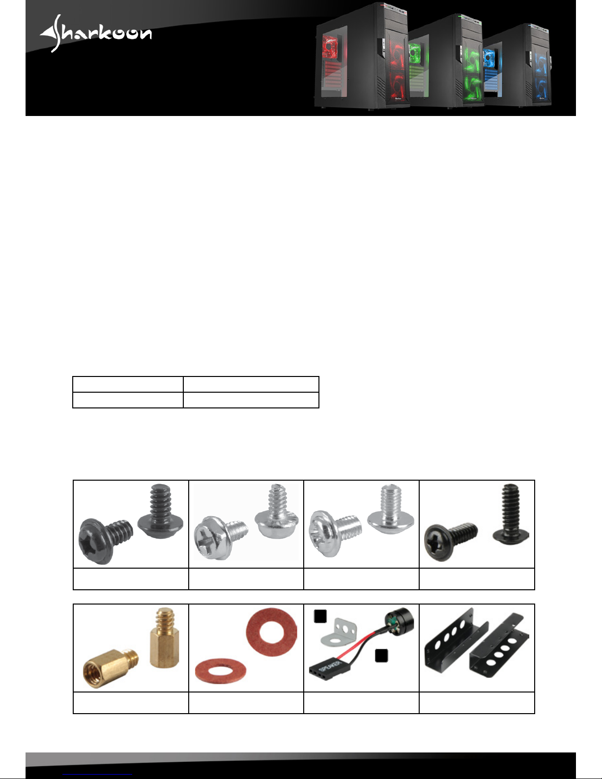
• Accessoryset:
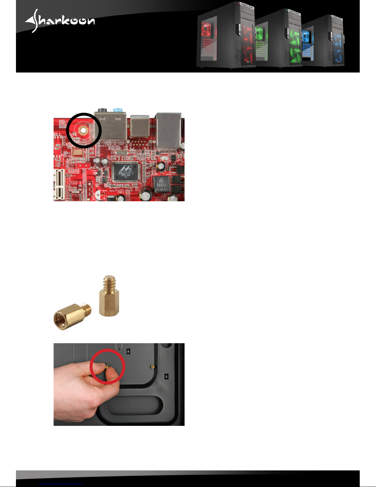
Screwsformainboard
mounting
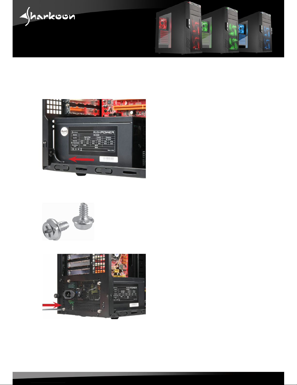
ScrewsforPSUmounting Screws for drive mounting Screws for HDD mounting
Stand-offsformainboard Washers Lockattachment(A)and
speaker(B)
Mountinganglesfor3.5"
devices
A
B