Sharkoon USB LANPORT 100 User manual

USB LANPORT 100 / 400
ENGLISH
USB LANPORT 100 / 400
Manual
english

USB LANPORT 100 / 400
ENGLISH
Content
1. Features
2. Parts and accessories
3.The device at a glance
4. Getting started
4.1 Hardware installation
4.2 Software installation (Windows for example)
5.The user interface
5.1The user interface’s menu bar
5.1.1The File menu
5.1.1.1The Setting submenu
5.1.1.2 Exiting the program (Quit entry)
5.1.2The View menu
5.1.3The Help menu
5.2The context menus
5.2.1The USB server context menu
5.2.1.1 Backup Firmware
5.2.1.2 Update Firmware
5.2.1.3 Change Password
5.2.1.4 Restart Server
5.2.2The USB devices context menu
6. Configuration via web interface
6.1 Device Status
6.2 Network
6.3 Reset device
6.4 Factory Default
6.5 Firmware Update
6.6 Password Change
7. Important notes
8. Example of use (Windows XP)

USB LANPORT 100 / 400
ENGLISH
Dear customer!
Congratulations for purchasing one premium quality SHARKOON
product.
For a long life time and to take full advantage of this product we
recommend that you read this manual completely.
Have a good time with our product!
SHARKOONTechnologies GmbH
1. Features
• 1-port(USBLANPort100)or4-port(USBLANPort400)USB
server
• AllowsconnectinganyUSBdevicetoaLAN
• SuitableforanyUSBdevices(e.g.USBsticks,USBprinters,
external hard disk drives etc.)
• Externalinterfaces(USBLANPort100):1xUSB2.0,1xLAN
(RJ-45)
• Externalinterfaces(USBLANPort400):4xUSB2.0,1xLAN
(RJ-45)
• Compactdesign
• PowerLEDandresetbutton

USB LANPORT 100 / 400
ENGLISH
2. Parts and accessories
• USBLANPort(A)
• Poweradapter(B)
• Patchcable(C)
• ToolsCDincl.softwareandextensivemanual(PDF/D)
A
B C
D

USB LANPORT 100 / 400
ENGLISH
3.The device at a glance
A
AA
A
B
B
BB
C
C
C
D
D
D
D
E
E
E
E
A – Networkconnector(RJ-45)
B – Powerconnector(5V/DC)
C – Reset button
D – PowerLED
E – USB connector(s)
USBLANPort100 USBLANPort400

USB LANPORT 100 / 400
ENGLISH
4. Getting started
4.1 Hardware installation
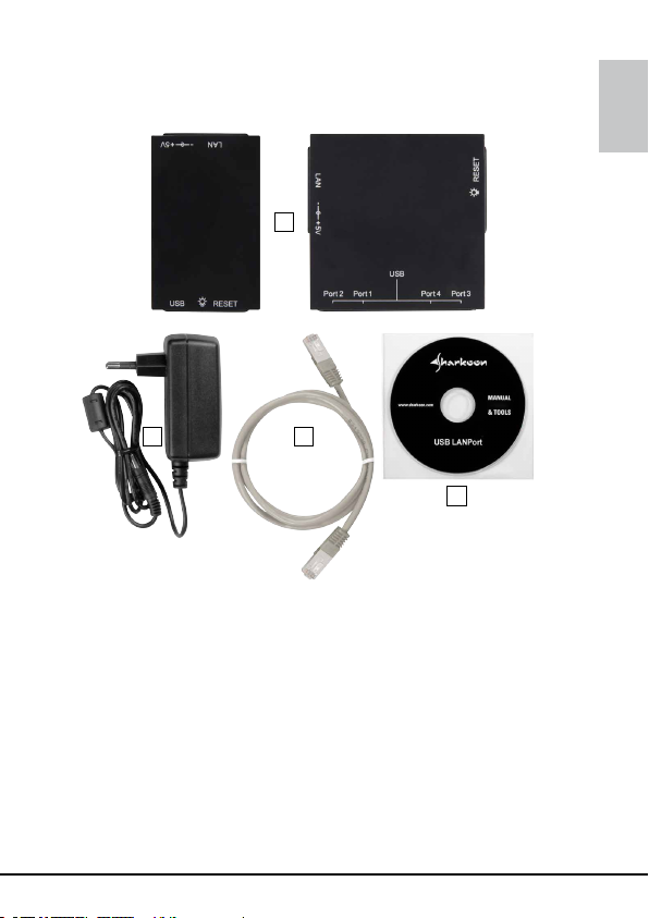
1. Connect the included patch cable to the USB LANPort’s
network connector and an available network connector of
yourswitch/hub/router/PCorsimilar.
2. ConnecttheincludedpoweradaptertotheUSBLANPortand
a wall outlet.The device will boot automatically.
4.2 Software installation (Windows for example)
1. InserttheincludedToolsCDintoyourCD/DVDdrive.
2. Use the Windows Explorer to open the directory of the
insertedTools CD.
3. Double click (left mouse button) “Setup.exe”. The installation
will start.
Follow the installation wizard’s instructions.
4. To complete the installation you will be prompted to reboot
your PC. Confirm this indication.
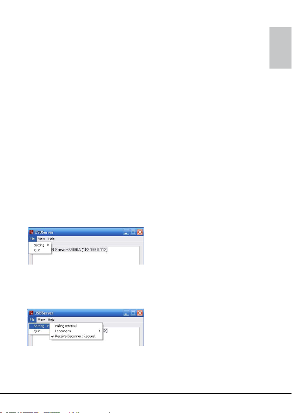
5. Aftersuccessfullyrebootingyoursystem,thefollowingicon
willappearonyourdesktop:
Double-click(leftmousebutton)thisicontolaunchthe
software.
Note:
You need to install this server software on every PC from
which you want to access the USB LANPort.
6. Connect the USB device(s) to the USB port(s) of the
USBLANPort.

USB LANPORT 100 / 400
ENGLISH
5.The user interface
Firstsetthedesiredlanguagefortheuserinterface:
File>Setting>Languages:
A – Menubarcontainingtheentries“File“,“View“and“Help“
B – USB server with appropriate IP address
C – USB device attached to the USB server (for example a
USBstick).Greenicon=deviceavailable,redicon=
device not available
D – “Search“button:byclicking(leftmousebutton)this
button the search for devices connected to the USB
server will be started
E – “Config“ (configuration) button (only shown when the
AB
D E
C
F

USB LANPORT 100 / 400
ENGLISH
USBserverhasbeenselected):left-clickthisbuttonto
open the USB server’s web interface
F – “Connect“ button (only shown when an attached USB
devicehasbeenselected):left-clickthisbuttontoselect
the according USB device and to lock it for other users
Note:
The software will detect the connected USB server and asso-
ciated devices automatically. Furthermore the USB server sup-
ports automatic and manual IP address assignment; automatic
address assignment via DHCP is selected by default.
In case your firewall prompts you during the installation process
allow the USB server to access the respective network resour-
ces.
5.1 The user interface’s menu bar
5.1.1 The File menu
The File menu offers the submenu “Setting“ and the entry “Quit“.
5.1.1.1 The Setting submenu
The Setting submenu contains the entries “Polling Interval“ and
„ReceiveDisconnectRequest“aswellasthesubmenu“Langu-
ages“

USB LANPORT 100 / 400
ENGLISH
1. The“Languagessubmenu”:
Fromtheip-outmenuselectthedesiredlanguageforthe
user interface.
2. The“PollingInterval”entry:
This entry lets you define whether and – if yes – in which
interval the USB server will poll the status of the connected
USB device(s).
After selecting this menu entry the following window will
openup:
Enter“0”todeactivatethisfunction.
Enteranyvalue>20secondstoactivatethisfunctionandto
set the interval.
3. The“ReceiveDisconnectRequest”entry:
In case a device is already in use by user A and user B wants
toaccessthisdevicesimultaneouslyhecansendthefollow-
ingrequesttoB:

USB LANPORT 100 / 400
ENGLISH
Thereceiptofthisautomatedrequestmaybeturnedon/offhere.
5.1.1.2 Exiting the program (Quit entry)
Select this menu entry to quit the program.
5.1.2 The View menu
The view menu offers the alternatively selectable entries “Ser-
vers And Devices“ and “Devices Only“.
1. The“ServersandDevices”entry:
Select this option to display both the USB Server and
connected USB devices in the user interface.
2. The“DevicesOnly”entry:
Ifthisoptionhasbeenselected,theuserinterfacewillonly
show the attached USB devices.

USB LANPORT 100 / 400
ENGLISH
5.1.3 The help menu
Via the “About“ entry you can access some program informa-
tion.
5.2 The context menus
Byright-clickingtheUSBserverentryorthedevicesentryinthe
user interface you can access the according context menus.
The devices context menu differs depending on whether the de-
vice is available (green icon) or blocked (red icon).

USB LANPORT 100 / 400
ENGLISH
5.2.1 The USB server context menu
A
B
C
E
D
A – Enter a name for the USB server here
B – DHCPon(manualIPaddressoff)/DHCPoff(manualIP
address on)
C – Define which port(s) shall be connected during program
start-upautomatically
D – “Set“savesyourchanges,“Cancel“discardsthem
E – Theentries“BackupFirmware“,“UpdateFirmware“,
“Change Password“ and “Restart Server“

USB LANPORT 100 / 400
ENGLISH
5.2.1.1 Backup Firmware
The USB server offers the possibility to backup the firmware.
Thepop-upwindow(seebelow)alreadyoffersatargetpathfor
the backup file. Via “Browse” you can change this default path.
“Submit”startsthebackup,“Cancel”willterminatetheaction.
5.2.1.2 Update Firmware
In case you have a more actual version of the USB server’s firm-
ware available you may update the current firmware version via
this entry. With “Browse” you select the locally saved update
version. “Submit” starts,“Cancel” terminates the update pro-
cedure.
A current firmware version can be found at www.sharkoon.com.
5.2.1.3 Change Password
In this input window (see below) you may assign a new pass-
word. This password is required to configure different settings
of the USB server.

USB LANPORT 100 / 400
ENGLISH
5.2.1.4 Restart Server
Select this entry to restart the USB server. A restart may be ne-
cessary when the server does not react or other problems have
occurred.
You may also force a restart by pressing the reset button on the
device.
5.2.2 The USB devices context menu
1. The details entry displays some information regarding the
attached devices.

USB LANPORT 100 / 400
ENGLISH
2. The “Request Disconnect“ entry is used to send a message
to the current user of a blocked device to ask him to unblock
thedevice:
This entry only appears when the device is blocked (red icon).
6. Configuration via web interface
1. StarttheUSBserversoftwarebydouble-clicking(leftmouse
button) the program icon.
2. Start your browser.
3. Enter the USB server’s IP address (without “http://” or
“www” put in front) into the browser’s address line. The IP
address assigned to the USB server can be found from the
userinterfaceoftheUSBserverprogram:
orfromtheUSBserver’scontextmenu:

USB LANPORT 100 / 400
ENGLISH
Alternatively select the USB server’s entry from the user
interfaceandclick“Cong“:
4. The browser will display the USB server’s web interface
afterwards.

USB LANPORT 100 / 400
ENGLISH
6.1 Device Status
A – Left-clickthelinktoselecttherespectiveentry.
B – This area displays various USB server information:
Server Name, Manufacturer, Model, Firmware Version
andServerUp-Time(timeelapsedsinceserverhasbeen
started).
C – This area displays various information regarding the
connected device: Device Name, Link Status, Device
Status and Current User.
A
B
C

USB LANPORT 100 / 400
ENGLISH
6.2 Network
A – Left-clickthelinktoselecttherespectiveentry.
B – Thisareadisplaysthecurrentnetworkstatus:IPSetting
(automaticormanualIPaddressassignment),IPAddress
(IPaddressassignedtotheserver),SubnetMask,MAC
Address (the server’s MAC address).
C – This area allows configuring the network settings.
With “DHCP Setting” you define whether the network
address shall be assigned automatically (Enable) or
manually (Disable).
The respective manual settings you enter into the areas
“IP Address” and “Subnet Mask”.
With “Server Name” you may define your own server
name.
To protect the server settings from unwanted changes
you need to assign a “Password”.
D – “Submit” saves your changes while “Clear” will discard
them.
A
B
C
D

USB LANPORT 100 / 400
ENGLISH
6.3 Reset device
A – Left-clickthelinktoselecttherespectiveentry.
B – Perform a reset after entering the assigned password
into the “Password” area and confirm by clicking the
“Submit” button.
6.4 Factory Default
A
A
B
B
A – Left-clickthelinktoselecttherespectiveentry.
B – To recover the factory default settings enter the pass-
word into the “Password” area and conrm by left-
clicking the “Factory Default” button.

USB LANPORT 100 / 400
ENGLISH
6.5 Firmware Update
B
C
A – Left-clickthelinktoselecttherespectiveentry.
B – Toperformarmwareupdate,downloadtherespective
software from our website and save it locally.Then enter
the according password (see above) into the “Password”
area and select the source path of the local update file
with “Search”.
C – “Submit” will confirm and start the update procedure.
“Clear” cancels the action.
6.6 Password Change
A
B
Other manuals for USB LANPORT 100
1
This manual suits for next models
1
Table of contents