Sharp AY-XPC12PU User manual

PLASMACLUSTER UNIT
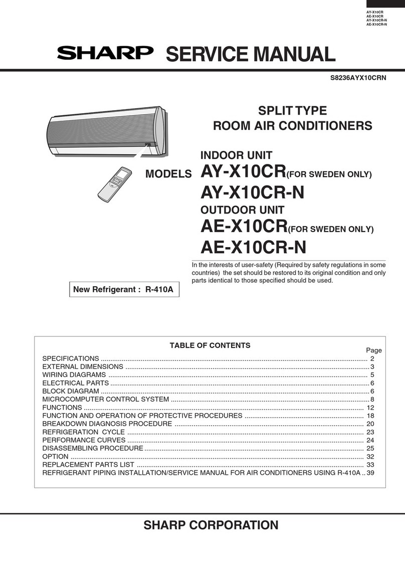
SERVICE MANUAL
AY-XPC12PU
SB211AYXPC2PU/T
Parts marked with " " are important for maintaining the safety of the set. Be sure to replace these parts with specified ones for maintaining the
safety and performance of the set.
This document has been published to be used for
after sales service only.
The contents are subject to change without notice.
CHAPTER 1. PRODUCT SPECIFICATIONS
[1] SPECIFICATION............................................ 1-1
[2] EXTERNAL DIMENTIONS............................. 1-2
[3] ELECTRICAL PARTS .................................... 1-3
[4] WIRING DIAGRAMS...................................... 1-3
CHAPTER 2. EXPLANATION OF CIRCUIT AND
OPERATION
[1] BLOCK DIAGRAMS....................................... 2-1
[2]
MICROCOMPUTER CONTROL SYSTEM
........... 2-2
[3] FUNCTION..................................................... 2-3
[4] OPERATION MANUAL .................................. 2-6
CHAPTER 3. TROUBLE SHOOTING GUIDE
[1] SELF-DIAGNOSIS FUNCTION.....................3-1
[2] THERMISTOR TEMPERATURE CHAR-
ACTERISTICS...............................................3-8
.................................
....
3-8
3-9
CHAPTER 4. DISASSEM
BLINGPROCEDURE
[1] INDOOR UNIT
INDOOR UNIT
...............................................4-1
CHAPTER 5. INSTALLATION INSTRUCTION
[1] .............................................5-1
[2] ..............................4-4
Parts Guide
TopPage
CONTENTS
MODEL
In the interests of user-safety (Required by safety regulations in some countries) the set should
be restored to its original condition and only parts identical to those specified should be used.
AY-XPC07PU
AY-XPC09PU
AY-XPC12PU
[3] AIR CONDITIONER OPERATION IN
THERMISTOR ERROR
[4] GENERAL TROUBLESHOOTING CHART
SPLIT TYPE
ROOM AIR CONDITIONER
(INDOOR UNIT)

1 – 1
AHXPC12LV Service Manual
CHAPTER 1. SPECIFICATION
[1] SPECIFICATION
AY-XPC12PU
Electrical data
High dB(A)
Low dB(A)
Silent dB(A)
High dB(A)
Low dB(A)
Silent dB(A)
Width inch (mm)
Height inch (mm)
Depth inch (mm)
Fan system
High CFM (m3/min)
Low CFM (m3/min)
Silent CFM (m3/min)
High CFM (m3/min)
Low CFM (m3/min)
Silent CFM (m3/min)
High rpm
Low rpm
Silent rpm
High rpm
Low rpm
Silent rpm
Connections
inch (mm)
inch (mm)
Drain hose inch (mm)
Others
V
Hz
Evaporator
Refrigerant
lb (kg)
PFILMA283JBEA
CKITTA159AKKZ
Flare type
A: 3/8" (Flared connection 3/8") (9.52)
B: 1/4" (Flared connection 1/4") (6.35)
Refrigerant coupling
Insulation O.D. Φ1.14 (29), Connected part O.D.
Φ0.63 (16)
Rated frequency
Reted voltage
Net weight
CRMC-A868JBEZ
Air flow quantity
(Heating)
Fan speed
(Cooling)
ITEMS
Phase
INDOOR MODEL
Cluster generator
Rmote controller
Refrigerant system
Sound Presure Level
(Cooling)
Sound Presure Level
(Heating)
Net dimensions
Fan motor
Air flow quantity
(Cooling)
Refrigerant tube size
(A:Gas line,B:Liquid line)
Fan speed
(Heating)
Fan
Air filters
38
26
28
36 7/32 (920)
11 13/32 (290)
22 (10)
CMOT-A562JBKZ
8poles, 30W
Cross-flow fan Φ110
9 7/16 (240)
AY-XPC07PU
Single
208/230
60
Louver fin and Grooved tube type
R410A
-
-
332 ( 9.4 )
198 ( 5.6 )
-
332 ( 9.4 )
230 ( 6.5 )
-
1000
660
-
1000
740
-
39
Louver fin and Grooved tube type
28
25
26
R410A
40
229 (6.5)
342 (9.7)
198 (5.6)
167 (4.7)
22
60
1030
660
580
1030
740
630
Cross-flow fan Φ110
186 (5.3)
9 7/16 (240)
22 (10)
342 (9.7)
AY-XPC09PU
Single
36 7/32 (920)
11 13/32 (290)
39
208/230
CMOT-A562JBKZ
8poles, 30W
AY-XPC12PU
R410A
60
Single
208/230
44
27
23
43
29
25
36 7/32 (920)
11 13/32 (290)
22 (10)
CMOT-A562JBKZ
8poles, 30W
381 (10.8)
214 (6.1)
175 (5.0)
408 (11.6)
244 (6.9)
186 (5.3)
1130
1200
700
630
Cross-flow fan Φ110
780
600
Louver fin and Grooved tube type
9 7/16 (240)

1 – 2
[2] EXTERNAL DIMENSION
Indoor unit
AY-XPC12PU
skrameRledoMemaNtraP
Fan motor
Louver motor
-1uF
'&02725&027$-%.=6+$&9-)
'&95027$-%==%<-
[3] ELECTRICAL PARTS
[4] WIRING DIAGRM
36.2 (920) 9.4 (240)
11.4 (290)
Remote controller
0.7 (18)
8.0 (204)
2.2 (57)
4)6*$-%==$9

Heat exchanger (PIPE) detect circuit Heat exchanger temp. thermistor
Liquid pipe VALVE detect circuit Liquid pipe temp. thermistor
2 – 1
AHXPC12LV 5GTXKEG/CPWCN
CHAPTER 2. EXPLAMATION OF CIRCUIT AND OPERATION
[1] BLOCK DIAGRAMS
AY-XPC12PU
Switching transformer

2 – 2
[2] MICROCOMPUTER CONTROL SYSTEM
1. Electronic control circuit diagram
AY-XPC12PU
:
0
5
0
:
5
S)
9
&
S)
9&
5
N5
N
5
,&
4
4
4
X)
9
&
N
5
&
9
X)
&
9
X)
N9
S)
&
9
X)
&
'
9
&
X)
4
51
4
51
5 :
:
5 N
9
&
X)
5
.¡
5
.¡
5
.¡
9
&
X) 9
&
X)
:
5 ¡
'%
*%/-)/
$&
$&
75
9
&
X)
17&
¡
5
N
9
S)
&
S)
9
&
9
S)
&
X)
&
9
5
N
5
:
.
5
15
9
&
9$&
X) 5
0¡
S)
9
&
S)
9
&
S)
9
&
S)
&
9
7+
52207(03.¡ć
7+
9$/9(7(03.¡ć
N
5
/289(5
0257(5
3&,
&1
5
:
.
9
&
X)
5
N
5
N
5
N
&
X)
9
235
/('
7,0(5
/('
/('
)XOO3RZHU
3&,
/('
51
4
N
5
& 9
X)
5
.)
.
5
)
5 .)
5 )
5
N)
5
N)
:
5
.)
'
X)
9
&
,&
N
5
N
5
N
5
X)
9
&
N
5
;3&
N
5
9
X)
&
.¡
:
5
&1
3*
9
9P
9V
9FF
&
9
X)
X)
9
&
N
5
-3
9
&
X
'
'1
$XWRRII
/('
4
%&1
1)
$
P+
3&
&
X)
9
='
(=$
='
+=01%
9
&
X)
3& ;
9
)8
$
,&
3
37,72
37,72
3722/
5(6(7
3;7(;&/.6
3;7
3,173
3;(;&/.
3;
5(*&
966
(966
9''
(9''
3
,173
37,72
37,72
3.56&.6&/
3.56,6'$
3.562
3.562
3.5,173
3.5,173
3.5,173
3.5,173
37,72,173
3
3
36'$$
36&/$
3,173
3,173
3
3
3
3
37,72
37,72,173
36&.6&/
35['
37['62
3627['
36,5['
36&.6&/
3
3
3$1,
3$1,
3$1,
3$1,
3$1,
3$1,
3$1,$95()0
3$1,$95()3
3
36&.6&/
36,5['6'$
3627['$1,
372
37,
3,173
3,173
-33
-3:
-3
/
/
&
9
S)
&
9
X)
N
5
N
5 N
5
9
X)
&
'
9
$
N
5
&1
,& %$%
%=
:
5
N¡
&1
5
N¡
:
5
N
:
.¡
5
5
N
N
5
N
5
5
.¡
5 :
5 :
¡
5
)
N
5
:
N¡
5
6 7+
3,3(7(03.¡ć
%52:1
%/8(
5('
/
/
N
5
&1
N
5
5
6:
$
9
'
'
+$-3
,&
0,3.
)%
&/
'
6
6
9''
9&&
3&
3&
3&
'
9
$
'1
'
'
'1
N
5
5
N)
5
N
,&
7/$
4
51
5
N &
9
X)
5
N
'
' ' '
3&
5
5
5
S)
9
&
S)
9
&
9
S)
&
&1
9''
7;'
5;'
722/
5(6(7
)/0'
*1'
:
5 N
:
5
5
N
5
N
9
9
9
9
9
9
99
9
9
9
9
9
9
9
9
9
9
9
9
9
1&
1&
1&
1&
1&
1&
1&
1&
1&
1&
$8;7(67581
:
+25,=217$/
1&
'&)$1
02725
$33/,&$7,2102'(/
*1'IRU
9/,1(
*1'IRU
9/,1(
*1'IRU
9/,1(
*1'IRU
9/,1(
*1'IRU
9/,1(
*1'IRU
9/,1(
*1'IRU
9/,1(
*1'IRU
9/,1(
*1'IRU
9/,1(
*1'IRU
9/,1(
*1'IRU
9/,1(
*1'IRU
9/,1(
(
51
1&
1&
*1'IRU
9/,1(
Ć3RZHUUDWLQJRIUHVLVWRUVQRW
LQGLFDWHGLQWKHGUDZLQJLV:
Ƹ7HVW3RLQW
287
35(+($7
*1'IRU
9/,1(
:,5(/(66
$872
5(67$57
$$<;3&38
$$<;3&38
$$<;3&38
*1'IRU
9/,1(
*1'IRU
9/,1(
1&
1&
1&
,1
9
9/,1(
*1'IRU
*1'IRU
9/,1(
72237,21
+($7(5
9
9
9/,1(
*1'IRU
*1'IRU
*1'IRU
9/,1(
*1'IRU
9/,1(
*1'IRU
9/,1(
9/,1(
*1'IRU
*1'
%&1
9/,1(
:LUH:LUHOHVV
7HPS5DQJH
6:,QSXW
6LJQDO2XWSXW

2 – 3
2. Printed wiring board
[3] FUNCTION
1. Restart control
Once the compressor stops operating, it will not restart for 180 sec-
onds to protect the compressor.
Therefore, if the operating compressor is shut down from the remote
control and then turned back on immediately after, the compressor will
restart after a preset delay time.
(The indoor unit will restart operation immediately after the ON switch
is operated on the remote control.)
2. Startup control
When the air conditioner starts in the cooling mode, if the room tem-
perature is 2℃higher than the set temperature the air conditioner
operates with the operating frequency at maximum.Then, when the set
temperature is reached, the air conditioner operates at the operating
frequency determined by fuzzy logic calculation, then enters the nor-
mal control mode after a while.
3. ON timer
The ON timer can be activated by pressing the ON timer button. When
the ON timer is activated, the operation start time is adjusted based on
fuzzy logic calculations 1 hour before the set time so that the room
temperature reaches the set temperature at the set time.
AY-XPC12PU
4. OFF Timer (Sleep Operation)
The OFF timer can be activated by pressing the OFF timer button.
When the OFF timer is set, the operation stops after the set time.
When this timer is set, the compressor operating frequency lowers for
quieter operation, and the room temperature is gradually varied after
one hour (reduced 1°C three times (max. 3°C) in heating, or increased
0.3°C three times (max. 1°C) in cooling or dehumidifying operation) so
that the room temperature remains suitable for comfortable sleeping.
Heating operation
Set temperature
Activation of
OFF timer
1 hour
later
Max.
1.5 hours
later
Max.
2 hours
later
Timer setting
reached
1 hour
later
Max.
1.5 hours
later
Max.
2 hours
later
Timer setting
reached
Activation of
OFF timer
Set temperature
-1
O
C
-1
O
C
-1
O
C
0.3
O
C0.3
O
C0.3
O
C
Cooling/dehumidifying operation
terminal board (green/yellow)
terminal board "L1"(blue)
terminal board "L2"(brown)
terminal board "2"(red)
CN1:fan motor
CN4:louver motor
CN6:plasmacluster generator
CN2:thermistor
BCN7:display board unit

2 – 4
5. Power ON start
6. Self-diagnostic malfunction code display
1) When a malfunction is confirmed, all relays turn off and a flashing
operation LED,timer LED,Plasamacluter LED is displayed to indi-
cate the type of malfunction.
When the air conditioner is in non-operating condition, holding
down AUX button for more than 5 seconds activates the malfunc-
tion code display function.
The operation continues only in the case of a serial open-circuit,
and the main relay turns off after 30 seconds if the open-circuit con-
dition remains.
In the case of a serial short-circuit, the air conditioner continues
operating without a malfunction code display, and the main relay
turns off after 30 seconds if the short-circuit condition remains.
The malfunction information is stored in memory, and can be
recalled later and shown on display.
2) The self-diagnostic memory can be recalled and shown on the dis-
play by stopping the operation and holding down AUX button for
more than 5 seconds.
(For details, refer to the troubleshooting section.)
7. AUTOMATIC AIR CONDITIONING
8. Airflow control
1) Press the SWING button on the remote control once.
The vertical adjustment louver will swing continuously.
2) Press the SWING button again when the vertical adjustment louver
is at the desired position.
The adjusted position will be memoried and will be automatically
set to the same position when operated the next time.
CAUTION: Never attempt to adjust the louvers manually.
Manual adjustment on the louvers can cause the unit to malfunc-
tion.
When the vertical adjustment louver is positioned at the lowest pos-
ition in the COOL or DRY mode for an extended period of time, con-
densation may result.
9. Difference of operation in Auto and Manual
modes
In the Auto mode, the temperature setting is automatically determined
based on the outside air temperature. In addition, the air conditioner
operation differs from the operation in the Manual mode as explained
below.
9.1. Difference relating to set temperature
10. Dehumidifying operation control
In the Dehumidifying mode, the temperature setting is automatically
determined based on the outside air temperature. In addition, the air
conditioner operation differs from the operation in the Manual mode as
explained below.
11. Full Power Operation
27ºC
+0
+0.5
-1.0
-1.5
25ºC
25ºC 28ºC
22ºC
22ºC
Room Temperature
Preset temperature
-
In the AUTO mode, the unit will automatically select COOL or HEAT
mode by comparing the room temperature and your desired tempera-
ture.
The unit will automatically switch between HEAT and COOL mode to
keep the desired temperature.
COANDA and MULTI SPACE button will be inactivated during AUTO
mode.
If the connecting wire “POWER ON” (POJP) is put on the PWB assem-
bly, when the power is supplied by turning on a circuit breaker, the air
conditioner automatically starts of operation in “AUTO”.
(Refer to Printed Wiring Board.).
AY-XPC12PU
8.1. VERTICAL AIR FLOW DIRECTION
8.2. HORIZONTAL AIR FLOW DIRECTION
Hold the horizontal airflow louver link and adjust the air flow direction.
In this operation, the air/air heat pump works at the maximum power
optimum louver direction to make the room cool or warm rapidly.
During operation, press the FULL POWER button.
and
TO CANCEL
Press the FULL POWER button again.
The FULL POWER operation will also be cancelled when the opera-
tion mode is changed, or when the unit is turned off.
NOTE:
The air/air heat pump will operate at “Extra HIGH” fan speed for 15
The remote control will display” “
The temperature display will go off.
The green FULL POWER lamp on the unit will light up.
The geen FULL POWER lamp on the unit will turn off
minutes, and then shift to “HIGH” fan speed. The vertical adjustment
louvre will be set obliquely downward.
You can not set the temperature or fan speed during the FULL
POWER operation.
To turn off the FULL POWER lamp, press the DISPLAY button.
+HDW
&RROLQJ
+HDW
&RROLQJ
+HDW
&RROLQJ
'HKXPLGLI\LQJ $XWRPDWLFVHWWLQJ&DQEHFKDQJHG
ZLWKLQsഘsഒXVLQJUHPRWHFRQWURO
$XWRPDWLFWHPSHUDWXUHVHWWLQJEDVHG
RQRXWVLGHDLUWHPSHUDWXUH
$XWRPRGH
E\SUHVVLQJ$8;EXWWRQ
$XWRPRGH
VHWE\UHPRWHFRQWURO
&DQEHFKDQJHGEHWZHHQᨺഘ
ᨺഒXVLQJUHPRWHFRQWURO
0DQXDOPRGH
&DQEHFKDQJHGEHWZHHQᨺഘ
ᨺഒXVLQJUHPRWHFRQWURO
Temperature setting method
2 – 5
12. Self Clean operation
13. Plasmacluster Ion function
Operating the Plasmacluster Ion button while the air conditioner is in
operation or in non-operation allows the switching of the operation
mode in the following sequence: “Air Clean operation” →“Stop”.
“
Plasmacluster operation” generates about equal amounts of (+)ions
and (-)ions from the cluster unit to provide clean air.
If the Plasmacluster Ion generation function is operated together with
the air conditioner operation, the indoor unit fan speed and louver
direction are in accordance with the air conditioner settings.
If the Plasmacluster Ion generation function is used without operating
the air conditioning function, the indoor unit fan operates at a very low
speed and the upper louver is angled upward and the lower louver
remains horizontal. (The airflow volume and direction can be changed
by using the remote control.)
14. Auto restart
When power failure occures, after power is recovered, the unit will
automatically restart in the same setting which were active before the
power failure.
14.1. Operating mode (Heat, Cool, Dry)
Temperature adjustment
(
within 3℉[2℃]range)automaticoperation
Temperature setting
Fan setting
Air flow direction
Power ON/OFF
Automatic operation mode setting
Swing louver
Plasmacluster mode
14.2. Setting not memorized
Timer setting
Full power setting
Self cleaning
14.3. Disabling auto restart function
By removing (cutting) jumper {(JP{)on the printed circuit board
(PCB), the auto restart function can be disabled.
15. Explanation of cluster circuit
The cluster unit generates cluster ions, which are circulated through-
out the room by the air flow created by the blower fan (indoor unit fan
motor) in the air conditioner unit.
1) When microcomputer output turns "H," the Q11 output changes to
"Lo," turning ON the SSR2 and applying 100 V to the cluster unit for
the generation of cluster ions (positive and negative ions).
AY-XPC12PU
Heating or Fan operation and Cluster operation are performed simulta-
neously.
The judgment of whether Heating or Fan operation is used is based on
the outside air temperature at 3 minutes after the start of internal
cleaning.
The operation stops after 40 minutes.
During this operation the horizontal louver moves and stays two posi-
tions.
It turns to the lower direction and stays for 30 minutes.
Next moves upward and stays for 10 minutes.
Heating operation Fan operation
24
O
C
Outside air temperature
2
3
12V
Q11 1
3
CN6
output
Microcomputer
Cluster unit

[2] Operation Manual
2 – 6
AY-XPC12PU
1
Press the HEAT, COOL , AUTO or DRY
button .
: HEAT : COOL
: AUTO : DRY
e green OPERATION lamp ( ) will t up.
TO TURN OFF
Press e STOP button.
e green OPERATION lamp ( ) will turn off.
2
Press the TEMPERATURE button to set
the desired temperature.
(HEAT/COOL/AUTO mode)
e temperature setting range:
61-86 °F (16-30 °C).
(DRY mode)
can be adjusted up to an addi-
tional ±3 °F (±2 °C) from e desired temperature
automatically by pressing e TEMPERATURE
button.
(Example: 1 °F / 1 °C )
(Example: 3 °F / 2 °C lower)
3
Press the FAN button to set the desired
fan speed.
In e DRY mode, e fan speed is preset to
AUTO and cannot be .
1
2
3
1
BASIC OPERATION
AUTO SOFT LOW
TURN OFF
NOTE:
TIPS ABOUT AUTO MODE
n e AUTO mode, e unit will automatically select COOL or HEAT mode by comparing e room
temperature and your desired temperature.
e unit will automatically switc between HEAT and COOL mode to keep e desired temperature.
COANDA and MULTI SPACE button will be inactivated during AUTO mode.
VERTICAL AIR FLOW DIRECTION
1
Press the SWING button ( ).
e vertical louver will swing.
2
Press the SWING button ( ) again
to stop at the desired position.
CAUTION:
Nevrs manually.
Manual adjustment of e louvers can cause
.
n e vertical adjustment louver is posi-
tioned at e lowest position in e COOL or
DRY mode for an extended period of time,
condensation may result.
NOTE:
e adjustment range is narrower n e
SWING range in order to prevent condensa-
tion from dripping.
HORIZONTAL AIR FLOW DIRECTION
ADJUSTING THE AIR FLOW
DIRECTION
1
2
HIGH
Louver link
Louver link

2 – 7
AY-XPC12PU
PLASMACLUSTER OPERATION
The Plasmacluster ion generator inside
the air conditioner will release positive and
negative Plasmacluster ions into the room
to reduce airborne mold.
1
During operation, press the PLAS-
MACLUSTER button.
The remote control will display “ ”.
The blue PLASMACLUSTER lamp will
light up.
TO CANCEL
Press the PLASMACLUSTER button again.
The blue PLASMACLUSTER lamp will turn off.
NOTE:
Use of the PLASMACLUSTER operation will
be memorized, and it will be activated the next
time you turn on the unit.
To perform Plasmacluster operation in FAN
only mode, press the PLASMACLUSTER but-
ton when the unit is not operating.
The mode symbol of the remote control will go
off and the fan speed cannot be set to AUTO.
Plasmacluster is Sharp’s original technology.
For more information, please visit:
http://www.sharp-pci.com/en/
1
By using this function, the louver will be
automatically adjusted to deliver comfort-
able air gently and quickly across the ceil-
ing or without cold/warm air blows
directly on you as much as possible.
In heat mode, vertical louver is set
downward to deliver the warm air down to
the In cool or dry mode, vertical air-
louver is set obliquely upward to de-
liver cool air to the ceiling in order to avoid
direct
1
During operation, press the COAN-
DA AIFLOW button.
(HEAT mode)
The remote control will display “ ”.
(COOL / DRY mode)
The remote control will display “ ”.
TO CANCEL
Press the COANDA AIFLOW button
again.
NOTE:
If you want COANDA AIRFLOW operation in
FULL POWER mode, press COANDA AIR-
FLOW button during FULL POWER operation.
The COANDA AIRFLOW setting and the
MULTI SPACE setting can not be used to-
gether.
1
COANDA (GENTLE COOL / HEAT)
AIRFLOW
1
NOTE:
The unit will operate at “Extra HIGH” fan
speed for 15 minutes for long distance deliv-
ery of conditioned air, and then shift to “HIGH”
fan speed after 15 minutes.
SILENT, COANDA, and FAN SPEED button
will be disabled during this operation.
Effectiveness of this function may differ de-
pending on the room layout, installation po-
sition of the unit, and insulation level of the
space concerned.
The unit will operate to cool or warm
multiple rooms in well insulated house by
pressing this button.
1
During cooling or heating operation,
press MULTI SPACE button.
The remote controller will display “ ”.
and fan speed icon will be changed to “ ”.
Louver angle will be changed to the position
for long distance delivery of cool or warm
air.
(HEAT mode)
The remote control will display “ ”.
(COOL / DRY mode)
The remote control will display “ ”.
TO CANCEL
Press MULTI SPACE button again.
MULTI SPACE

2 – 8
AY-XPC12PU
The air conditioner works at the maximum
power to makes the room cool or warm
quicker.
1
During operation, press the FULL
POWER button.
The remote control will display “ ” and
AIR FLOW symbol will get longer.
The temperature display will go off.
The green FULL POWER lamp ( )will
light up.
TO CANCEL
Press the FULL POWER button again.
The green FULL POWER lamp ( )will
turn off.
NOTE:
The air conditioner will operate at “Extra
HIGH” fan speed for 15 minutes, and then
shift to “HIGH” fan speed.
You can not set the temperature or fan speed
during the FULL POWER operation.
The unit will operate at “Extra LOW” fan
speed for comfort and in need of quieter
operation.
1During COOL, HEAT, and AUTO op-
eration, press the SILENT button.
The speed icon on the remote control will
display “SILENT”.
TO CANCEL
Press the SILENT button again.
1
FULL POWER OPERATION
SILENT OPERATION
1
When the 1.2.3.5h OFF TIMER is set, the
unit will automatically turn off after the set-
ting hours.
1
Press the 1.2.3.5h OFF TIMER but-
ton to set the desired time.
The orange TIMER lamp ( ) will light up.
The remaining time will be indicated on
the remote control in 1-hour increments.
TO CANCEL
Press the SET/C button.
Alternatively, press the 1.2.3.5h OFF
TIMER button.
The orange TIMER lamp ( ) will turn off.
NOTE:
The 1.2.3.5h OFF TIMER has priority over
TIMER ON and TIMER OFF.
If the 1.2.3.5h OFF TIMER is set while the unit
is not operating, the unit will operate at the
formerly set condition.
If TIMER ON and/or TIMER OFF are set,
TIMER CANCEL button cancels every setting.
1
CANCEL
1.2.3.5h OFF TIMER
CANCEL

2 – 9
AY-XPC12PU
TIMER OFF
1
Press the TIMER OFF button.
The TIMER OFF indicator will blink.
2
Press the TIME ADVANCE or RE-
VERSE button to set the desired
time.
The time can be set in 10-minute incre-
ments.
3
Press the SET/C button.
The orange TIMER lamp ( ) will light
up.
3
2
1
NOTE:
When the TIMER OFF is set, the temperature
setting is automatically adjusted to prevent
the room from becoming excessively cold
or warm, for example while you sleep. (Auto
Sleep function)
HEAT mode: One hour after the timer is set,
the temperature setting drops by 5 °F (3 °C).
COOL mode: One hour after the timer is set,
the temperature setting rises by 2 °F (1 °C).
TIMER OPERATION
TO CANCEL
Press the SET/C button.
The orange TIMER lamp ( ) will turn off.
The current time will be displayed on the re-
mote control.
TIMER ON
1
Press the TIMER ON button.
The TIMER ON indicator will blink.
2
Press the TIME ADVANCE or RE-
VERSE button to set the desired
time.
The time can be set in 10-minute incre-
ments.
3
Press the SET/C button.
The orange TIMER lamp ( ) will light
up.
4
Select the mode, temperature, and
fan speed as desired.
Press below buttons to select mode;.
: HEAT : COOL
: AUTO : DRY
Press the TEMPERATURE button ( or
) to set the desired temperature.
Press the FAN button to set the desired
fan speed.
CANCEL
TO CHANGE TIME SETTING
Cancel the TIMER setting, then set it
again
TO COMBINE TIMER ON AND
TIMER OFF
Timer on and timer off can be set up at
the same time
Set the TIMER OFF and TIMER ON. The
settings will be automatically com-
bined.
Example
(
Current time: 9:00 p.m.)
OFF TIMER at 11:00 p.m.
ON TIMER at 7:00 a.m.
The arrow ( or ) between the TIMER ON
indicator and the TIMER OFF indicator shows
which timer will activate
NOTE:
You cannot program the ON-TIMER and OFF-
TIMER to operate the unit at different tem-
peratures or other settings.
Either timer can be programmed to activate
prior to the other.
NOTE:
The unit will turn on prior to the set time to
allow the room to reach the desired tempera-
ture. (Awaking function)
1
3
2
AUTO SOFT LOW
HIGH

SELF CLEAN operation will reduce the
growth of mold fungus with Plasmacluster
ions and dry inside of the unit. Utilize the
operation at seasonal change over terms.
1
Press the SELF CLEAN button when
the unit is not operating.
The remote control will display “ ”.
(The “ ” will disappear automatically in
1 minute.)
The blue PLASMACLUSTER lamp ( )
will light up.
The unit will stop operation after 40 min-
utes.
TO CANCEL
Press the SELF CLEAN button.
The blue PLASMACLUSTER lamp will
turn off.
NOTE:
You cannot set the temperature, fan speed, air
direction or timer setting during the SELF
CLEAN operation.
Mold fungus already grown can not be
eliminated by this operation.
SELF CLEAN OPERATION
1
Press the DISPLAY button when the lamps
on the unit are too bright. (The green OP-
ERATION lamp and the orange TIMER
lamp cannot be turned off.)
1
During operation, press the DIS-
PLAY button.
The blue PLASMACLUSTER lamp ( ),
5°F/-15°C AUTO OFF lamp and/or the
green FULL POWER lamp ( ) will turn
off.
TO LIGHT UP
Press the DISPLAY button again.
DISPLAY BUTTON
1
Use this mode when the remote control is
not available.
TO TURN ON
Press the AUX button.
The green OPERATION lamp ( ) will light
up.
The mode and the temperature setting are
automatically selected according to the room
temperature and the outdoor temperature
when the unit is turned on. The fan speed is
set to AUTO.
TO TURN OFF
Press the AUX button again.
The green OPERATION lamp ( ) will turn
off.
AUXILIARY MODE
2 – 10
AY-XPC12PU
AUX

AY-XPC12PU
3 – 1
AHXPC12LV 5GTXKEG/CPWCN
CHAPTER 3. TROUBLESHOOTING GUIDE
[1] SELF-DIAGNOSIS FUNCTION
To display the self-diagnosis, hold down the AUX button for over 5 seconds on the indoor unit when the indoor unit is not operating.
The operation lamp (green), timer lamp (orange) and Plasmacluster lamp (blue) flash to indicate the information of malfunction.
If the power cord is unplugged or the circuit breaker is turned off, the self-diagnosis memory is lost.
<Display of self-diagnosis result>
The operation lamp (green) and the Plasmacluster lamp (blue) flash in synchronization with the timer lamp (orange).
Timer lamp (1 cycle)
ON
OFF
5-second OFF
1-second
OFF
1-second
OFF
1-second
OFF
1-second
OFF
1-second
ON
1-second
ON
1-second
ON
1-second
ON
1-second
ON
1st 2nd 3rd 4th 5th
1.DESCREPTION OF SELF-DIAGNOSIS FUNCTION
Remark
When reading the result of self-diagnosis, you shall combine it with outdoor unit indication in order to get a correct conclusion.
(LED1)
Maf
o
Normal
condition
Normal
blinking O O O O O Timer (Orange) 0 0 Normal
Operation (Green)
Plasmacluster (Blue)
Indoor and
outdoor units
do not oper-
ate.
1-time O O O O O Timer (Orange) 1 0 Outdoor unit
thermistor
short-circuit
Heat exchanger
thermistor short
circuit error
1) Measure the resistance
of the outdoor unit
thermistors.
2) Check the lead wire
of the outdoor unit
thermistor for torn
sheath and shortcircuit.
3) 1) 2):Normal
1) Replace the outdoor
unit thermistor
assembly.
2) Replace the outdoor
unit thermistor
assembly.
3) Replace the outdoor
unit control PCB
assembly.
O Operation (Green)
Plasmacluster (Blue)
O O O O O Timer (Orange) 1 Outdoor temperature
thermistor short
circuit error
O Operation (Green)
O Plasmacluster (Blue)
O O O O O Timer (Orange) 2 Suction thermistor
short circuit error
O Operation (Green)
O Plasmacluster (Blue)
O O O O O Timer (Orange) 3 Suction thermistor
(for unit A, B, C)
short circuit error
O Operation (Green)
O O Plasmacluster (Blue)
2.CHART FOR READING SELF-DIAGNOSIS RESULT
Operation lamp(Green)
Timer lamp(orange)
Plasmacluster lamp(Blue)
AUX

3-2
Mf
o
Indoor and
outdoor units
do not
operate.
2-time O O O O O Timer (Orange) 2 0 Cycle
temperature
Compressor high
temperature error
1) Check the outdoor unit
air outlet for blockage.
2) Check if the power
supply voltage is AC
230V at full power.
3) Check the pipe
connections for
refrigerant leaks.
4) Measure resistance
of the outdoor unit
compressor thermistor.
5) Check the expansion
valve for proper
operation.
1) Ensure unobstructed
outdoor unit air
outlet.
2) Connect power
supply of proper
voltage.
amount of refriger-
ant.
4) Replace the outdoor
unit compressor
thermistor assem-
bly.
5) Replace the expan-
sion valve coil,
expansion valve or
outdoor unit control
PCB assembly.
O Operation (Green)
Plasmacluster (Blue)
Indoor unit
operates.
Outdoor
unit does
not operate
temporarily
O O O O O Timer (Orange) 1 Compressor
discharge overheat.
(Temporary stop for cycle
protection)
-
O Operation (Green)
O Plasmacluster (Blue)
O O O O O Timer (Orange) 2 Outdoor unit heat
exchanger overheat.
(Temporary stop for cycle
protection)
-
O Operation (Green)
O Plasmacluster (Blue)
O O O O O Timer (Orange) 3 Indoor unit heat
exchanger overheat.
(Temporary stop for cycle
protection)
-
O Operation (Green)
O O Plasmacluster (Blue)
O O O O O Timer (Orange) 4 IPM high
temperature error
Measure resistance of the
heat-sink thermistor.
-
O Operation (Green)
O Plasmacluster (Blue)
Indoor and
outdoor
units do not
operate.
OOOOO
OOOOO
OO
Timer (Orange) 5 IPM high
temperature error
Replace the outdoor unit
control PCB assembly.
-
O Operation (Green)
O O Plasmacluster (Blue)
Plasmacluster (Blue)
AY-XPC12PU
Indoor unit
operates.
Outdoor
unit does
not operate
temporarily.
3-time Timer (Orange)
tion
Temporary stop
due to dehumidi-
fying operation
(Temporary stop for
cycle protection)
-
Operation (Green)
30Dry opera-
Heat
operation
5℉/-15℃
AUTO OFF
Measure the resistance
of outdoor temperature
thermister.
Replace the outdoor
unit thermister assem-
bly
Indoor and
outdoor
units do not
operate.
5-time O O O O O Timer (Orange) 5 0 Outdoor unit
thermistor
open-circuit
Heat exchanger
thermistor open
circuit error
1) Check connector of
outdoor unit thermistor
for secure installation.
2) Measure resistance of
outdoor thermistors
3) Check the lead wires
of thermistors on the
outdoor unit control
PCB for open-circuit.
4) 1) 2) 3):Normal
1) Correct the installa-
tion
2) Replace the outdoor
unit thermistor
assembly.
3) Replace the outdoor
unit thermistor
assembly.
4) Replace the outdoor
unit control PWB
assembly.
O O Operation (
Green
)
Plasmacluster (Blue)
O O O O O Timer (Orange) 1 Outdoor temperature
thermistor open
circuit error
O O Operation (
Green
)
O Plasmacluster (Blue)
O O O O O Timer (Orange) 2 Suction thermistor
open circuit error
O O Operation (
Green
)
O Plasmacluster (Blue)
O O O O O Timer (Orange) 3 Suction thermistor
open circuit error
O O Operation (
Green
)
O O Plasmacluster (Blue)
O O O O O Timer (Orange) 4 Discharge thermistor
open circuit error
O O Operation (
Green
)
O Plasmacluster (Blue)
O O O O O Timer (Orange) 5 Heat sink thermistor
open circuit error
O O Operation (
Green
)
O O Plasmacluster (Blue)

3 - 3
Problem
symptom
Outdoor
unit
indication
(LED1)
Indoor unit Malfunction
No.* Content of diagnosis Check point Action
oLamp Main Sub Main Sub
Indoor and
outdoor
units do not
operate.
6-time O O O O O Timer (Orange) 6 0 Outdoor unit
DC Current
DC over current
error
Go to “DC Over Current Error (6-0 error)”.
O O Operation (
Green
)
Plasmacluster (Blue)
O O O O O Timer (Orange) 1 IPM pin level error Check the IPM is attached
correctly to the outdoor unit
IPM PWB.
Replace the outdoor
unit IPM PWB
assembly.
O O Operation (
Green
)
O Plasmacluster (Blue)
Indoor and
outdoor
units do not
operate.
7-time O O O O O Timer (Orange) 7 0 Outdoor unit
AC Current
AC over current error 1) Ensure unobstructed air
unit air outlet.
2) Check the outdoor unit
fan motor.
1) Ensure unobstructed
outdoor unit air
outlet.
2) Check the outdoor
unit fan motor.
O O O Operation (
Green
)
Plasmacluster (Blue)
O O O O O Timer (Orange) 1 AC current error
when OFF
1) IPM continuity check 1) Replace the outdoor
IPM PWB
O O O Operation (
Green
)
O Plasmacluster (Blue)
O O O O O Timer (Orange) 2 AC maximum current
error
1) Ensure unobstructed air
unit air outlet.
2) Check the outdoor unit
fan motor.
1) Ensure unobstructed
outdoor unit air
outlet.
2) Check the outdoor
unit fan motor.
O O O Operation (
Green
)
O Plasmacluster (Blue)
O O O O O Timer (Orange) 3 AC current 1) Replace the outdoor unit
control PCB assembly.
amount of refrigerant.
3) Correct refrigerant clogs.
(Stop valve, pipe,
expansion valve)
1) Replace the outdoor
unit control PCB
assembly.
amount of refriger-
ant.
3) Correct refrigerant
clogs. (Stop valve,
pipe, expansion
valve)
O O O Operation (
Green
)
O O Plasmacluster (Blue)
Indoor and
outdoor
units do not
operate.
8-time O O O O O Timer (Orange) 8 0
0
Abnormal
wire check
Abnormal wire check
error
1) Check the expansion
valve.
2) Are four expansion
valves connected by
mistake.
3) Check the wiring
between units.
1) Replace the outdoor
control board
assembly.
2) Reattach
3) Check the wiring
between units.
O Operation (
Green
)
Plasmacluster (Blue)
OOOOO
O
Timer (Orange)
O Operation (
Green
)
Plasmacluster (Blue)
Indoor and
outdoor
units do not
operate.
9-time
O O O O O Timer (Orange)
9
4 Cycle
temperature
4 way valve error or
Gas leak error
1) Check the unit thermistor
TH2 (exchange) and
TH3 (pipe temperature)
are installed in correct
portions.
2) Check if the refrigerant
volume is abnormally
low.
3) Check the 4-way valve
for proper operation.
1) Correct the
installation.
2) Change the
refrigerant.
3) Replace the 4-way
valve.
O O Operation (
Green
)
O Plasmacluster (Blue)
AY-XPC12PU
Cycle
temperature
Thermistor
installation error
or 4-way valve
error.
1)Check the ther-
mistor (heat
exchanger) and (2-
way valve) are
installed in correct
positions.
1)Correct the instal-
lation.
2)Check resistance of
thermistors (heat
exchanger and 2-
way valve).
2)Change the
specified amount
of refrigerant.
3)Check the 4-way
valve for proper
operation.
3)Replace the 4-
way valve.
4)No abnormality
found in above
inspections (1), (2),
(3).
4)Replace the out-
door unit control
PWB assembly.
Indoor and
outdoor
units do not
operate.
10-time O O O O O Timer (Orange) 10 0 EEPROM
error
EEPROM (outdoor)
data error
-Replace the outdoor
unit control PWB
assembly.
O O Operation (Green)
Plasmacluster (Blue)
O O O O O Timer (Orange) 1 EEPROM (outdoor)
data error
O O Operation (Green)
O Plasmacluster (Blue)

AY-XPC12PU
3-4
Problem
symptom
Outdoor
unit
indication
(LED1)
Indoor unit Malfunction
No.* Content of diagnosis Check point Action
oLamp Main Sub Main Sub
Indoor and
outdoor
units do not
operate.
10-time O O O O O Timer (Orange) 10 2 EEPROM
error
EEPROM (outdoor)
data error
- Replace the outdoor
unit control PWB
assembly.
O O Operation (Green)
O Plasmacluster (Blue)
Indoor and
outdoor
units do not
operate.
11-time O O O O O Timer (Orange) 11 0 Outdoor unit
DC fan
Outdoor unit DC fan
rotation error
1) Check connector CN3
of the outdoor unit DC
fan motor for secure
installation.
2) Check the outdoor unit
fan motor for proper
rotation.
3) Check fuse FUSE5.
4) Outdoor unit control
PWB
1) Correct the installa-
tion.
2) Replace the outdoor
unit fan motor.
3) Replace the outdoor
unit control PWB
assembly.
4) Replace the outdoor
unit control PWB
assembly.
O O O Operation (Green)
Plasmacluster (Blue)
O O O O O Timer (Orange) 1 Outdoor unit DC fan
driver IC error
1) Check if the fan IPM
terminal resistance
values are uniform.
2) Outdoor unit fan motor
continuity check.
1) Replace the outdoor
unit control PWB
assembly.
2) Replace the outdoor
unit fan.
O O O Operation (Green)
O Plasmacluster (Blue)
O O O O O Timer (Orange) 2 Outdoor unit DC fan
lock error
1) Check the outdoor unit
fan motor for proper
rotation.
2) 1): Normal
1) Replace the outdoor
unit control PWB
assembly.
2) Replace the outdoor
unit fan.
O O O Operation (Green)
O Plasmacluster (Blue)
O O O O O Timer (Orange) 3 Detection error of DC
fan negative rotation
before compressor is
driven
(Temporary stop for DC
fan circuit protection)
-
O O O Operation (Green)
O O Plasmacluster (Blue)
O O O O O Timer (Orange) 4 Detection error of
inverter current for
DC fan
- Replace the outdoor
unit control PWB
assembly.
O O O Operation (Green)
O Plasmacluster (Blue)
O O O O O Timer (Orange) 5 Outdoor unit DC fan
open connector error
1) Check connector CN3
of the outdoor unit DC
fan motor for secure
installation.
2) No abnormality found in
above inspection 1).
1) Correct the installa-
tion.
2) Replace the outdoor
unit control PWB
assembly.
O O O Operation (Green)
O O Plasmacluster (Blue)
Indoor and
outdoor
units do not
operate.
12-time O O O O O Timer (Orange) 12 0 Thermal fuse
in terminal
board
Thermal fuse error
in terminal board (for
power supply)
1) Check the thermal fuse
in terminal board (for
Power supply)
2) Check connector CN5 of
the outdoor unit.
3) 1) 2): Normal
1) Replace terminal
board for Power
supply.
2) Correct the installa-
tion.
3) Replace the outdoor
unit control PCB
assembly.
O O Operation (Green)
Plasmacluster (Blue)
Indoor and
outdoor
units do not
operate.
13-time O O O O O Timer (Orange) 13 0 DC
compressor
Compressor startup
error
1) Check the colors (red,
white, orange) of the
compressor cords for
proper connection.
(PWB side, compressor
side)
2) Check if the IPM terminal
resistance values are
uniform.
3) Check if outdoor main
relay (MRY1) turns on
and voltage of both end
of the condenser (C10)
has become DC290-
330V.
4) 1) 2) 3) : Normal
1) Correct the installa-
tion.
(U: Red, V: White, W:
Orange)
2) Replace the outdoor
unit control PWB
assembly.
3) Replace the outdoor
unit control PWB
assembly.
4) Replace the com-
pressor.
O O O Operation (Green)
Plasmacluster (Blue)
O O O O O Timer (Orange) 1 Compressor rotation
error.
(at 120° energizing)
O O O Operation (Green)
O Plasmacluster (Blue)
O O O O O Timer (Orange) 2 Compressor rotation
error
(at 180° energizing)
O O O Operation (Green)
O Plasmacluster (Blue)
Indoor and
outdoor units
operate.
O O O O O Timer (Orange) 3 Detection error of
inverter current
Check the circuit of
detection of inverter
current.
Replace the outdoor
unit control PWB
assembly.
O O O Operation (Green)
O O Plasmacluster (Blue)

3-5
AY-XPC12PU
Problem
symptom
Outdoor
unit
indication
(LED1)
Indoor unit Malfunction
No.* Content of diagnosis Check point Action
oLamp Main Sub Main Sub
Indoor and
outdoor
units do not
operate.
14-time O O O O O Timer (Orange) 14 0 Outdor unit
PAM
PAM over voltage
error
1) Check the AC power
supply voltage for
2) No abnormality found in
above inspection.
1) Correct the installa-
tion.
2) Replace the PWB
assembly.
O O O Operation (
Green
)
Plasmacluster (Blue)
O O O O O Timer (Orange) 1 PAM clock error Check the PAM clock for
proper input.
Replace the outdoor
unit control PWB
assembly.
O O O Operation (
Green
)
O Plasmacluster (Blue)
O O O O O Timer (Orange) 2 PAM under voltage
error
1) Check the AC power
supply voltage for
2) No abnormality found in
above inspection.
1) Correct the installa-
tion.
2) Replace the PWB
assembly.
O O O Operation (
Green
)
O Plasmacluster (Blue)
Indoor unit
operates.
Outdoor unit
does not
operate.
Lighting or
OFF
O O O O O Timer (Orange) 17 0 Wiring
between
units
Serial opencircuit 1) Check the wires between
units.
2) Check voltage between
N and 1 the indoor/
outdoor unit terminal
boards.
3) Check the outdoor unit
fuse.
4) Check 15-V,13-V and
5-V voltages on the
PCB.
Check resistance between
IPM terminals.
5) Check pins No.5 and 8
of connector CN3 of the
outdoor unit fan motor
for shortcircuit.
6) Outdoor unit control
PCB.
1) Connect stable
power supply.
Correct the wiring.
2) Replace the outdoor
unit control PWB
assembly.
3) Replace the fuse/
outdoor unit control
PWB assembly.
4) Replace the outdoor
unit control PWB
assembly.
5) Replace the outdoor
unit fan motor.
6) Replace the outdoor
unit control PWB.
O O Operation (
Green
)
Plasmacluster (Blue)
Indoor unit
operates.
Outdoor unit
does not
operate.
Lighting or
OFF
O O O O O Timer (Orange) 18 0 Wiring
between
units
Serial short-circuit
Serial erroneous
wiring
Check the wiring between
units.
Correct the wiring.
O O Operation (
Green
)
Plasmacluster (Blue)
Indoor and
outdoor
units do not
operate.
O O O O O Timer (Orange) 1 Check the wiring between
units.
Correct the wiring.
O O Operation (
Green
)
O Plasmacluster (Blue)
Indoor and
outdoor
units do not
operate.
Normal
blinking or
OFF
O O O O O Timer (Orange) 19 0 Indoor unit
fan
Indoor unit fan error 1) Check the indoor fan
motor for proper rotat-
ing operation.
(Check fan lock.)
2) Check the lead wire of
the indoor fan motor for
open-circuit.
3) Check connector ofthe
indoor unit fanmotor for
secureinstallation.
4) 1) 2) 3): Normal
1) Replace the indoor
fan motor.
2) Replace the indoor
fan motor.
3) Correct the installa-
tion of the indoor
fan motor connec-
tor.
4) Replace the indoo-
runit control PCB.
O O O Operation (
Green
)
Plasmacluster (Blue)
Indoor and
outdoor
units do not
operate.
Normal
blinking or
OFF
O O O O O Timer (Orange) 20 0 Indoor unit
control PCB
EEPROM data error (EEPROM read data error) Replace the indoor unit
control PWB.
O O Operation (
Green
)
Plasmacluster (Blue)

AY-XPC12PU
3 – 6
Indoor and
outdoor
units oper-
ate.
Normal
blinking
or OFF
{{{{{Timer (Orange) 26 1 Indoor unit
room tem-
perature
thermistor
Indoor unit room
temperature
thermistor
(1) Check connector of
thermistor for
secure installation.
(1) Replace the ther-
mistor.
{{ { Operation (Green)
{Plasmacluster(Blue)
Operation (Green)
Plasmacluster(Blue)
Operation (Green)
Plasmacluster(Blue)
(2) Check the tempera-
ture properties of
the thermistor.
(2) Replace the ther-
mistor.
{{{{{Timer (Orange) 2 Indoor unit
pipe tem-
perature
thermistor
Indoor unit pipe
temperature
thermistor
(1) Check connector of
thermistor for
secure installation.
(1) Replace the ther-
mistor.
{{ {
{
(2) Check the tempera-
ture properties of
the thermistor.
(2) Replace the ther-
mistor.
{{{{{Timer (Orange) 3 Indoor unit
valve tem-
perature
thermistor
Indoor unit valve
temperature
thermistor
(1) Check connector of
thermistor for
secure installation.
(1) Replace the ther-
mistor.
{{ {
{{
(2) Check the tempera-
ture properties of
the thermistor.
(2) Replace the ther-
mistor.
Problem
symptom
Outdoor
unit indi-
cation
(LED1)
Indoor unit Malfunc-
tion No.
Content of diagnosis Check point Action
Lamp Main Sub Main Sub
o
*Remark
The malfunction No. is calculated using the following way.
Example)
Indoor unit lamp oLamp Calculation Main Sub
168421
Timer (orange) OOOOO
Operation (Green) O O 4+1=5 5
Plasmacluster (blue) O 2 2
IPM CHECK METHOD
1. Turn off the power.
2. Make sure that the electrolytic capacitor voltage is approx. 0 V.
3. Remove all connectors of the IPM PWB.
4. Measure the resistance between terminals using a tester.
Measuring points of terminals are shown in the figure below.
Analog tester Normal Resistance Analog tester Normal Resistance
--+-
TP
TN
∞
*(Few MΩ)
TU
TN ∞
(Few MΩ)
VTUT
WTVT
retsetlatigiDyb:eulav)(*WT
IPM printed wiring board
REMOVE
REMOVE
TN TP
TU
TV
TW
REMOVE

AY-XPC12PU
3 – 7
DC Over Current Error (6-0 error)
*1 Check the connection of compressor lead wire on IPM PWB.
TU : RED
TV : WHITE
TW : ORANGE
*2 Refer to "IPM CHECK METHOD".
*3 Check the connection of compressor terminal marking.
Refer to " DISASSEMBLING PROCEDURE OUTDOOR UNIT".
*4 Check to make sure thermistors are installed in correct portions.
Refer to "THERMISTOR TEMPERATURE CHARACTERISTICS".
Yes
No
Yes
*1 No
abnormal
normal abnormal
abnormal
abnormal
abnormal
abnormal
*2
abnormal
normal
normal
normal normal
normal
normal
*3 Yes
abnormal
No
normal
Cooling mode
Heating mode
*4
*4
START
Replace IPM PWB.
Modify compressor terminal
marking.
Clean indoor heat exchanger.
Fix IPM PWB with screws securely.
Modify or replace termistor.
Are stop valves
(liquid and gas) close?
Does compressor
rotate?
Check IPM
lead wire.
Check
short circuit.
Check compressor
terminal.
Does compressor rotate?
Does compressor rotate
more than 30 seconds?
Is IPM PWB floating
from the heat sink?
Check the AC power
supply voltage when
compressor rotate.
(rated voltage±10%)
Cooling mode?
Check indoor heat
exchanger termistor and
discharge thermistor.
Check outdoor heat
exchanger termistor and
discharge thermistor.
Check indoor
heat exchanger.
Check outdoor
heat exchanger.
6-0 error memory is recorded.
Check the refrigerant amount.
Check the discharge pressure.
Check the installation condition.
Replace control board PWB.
Replace Compressor.
Fully open stop valves.
Modify the connection of
compressor lead wire on IPM
Connect stable power supply.
Clean outdoor heat exchanger.
Modify or replace termistor.
This manual suits for next models
2
Table of contents
Other Sharp Air Conditioner manuals

Sharp
Sharp AY -A07BE User manual

Sharp
Sharp AH-A07CR User manual

Sharp
Sharp AY-AP9KR User manual

Sharp
Sharp AH-XPC9RV User manual

Sharp
Sharp AF-Q60PX User manual

Sharp
Sharp AE-X3M18JR User manual

Sharp
Sharp UHL Series User manual

Sharp
Sharp AY-X09NCJ User manual

Sharp
Sharp AY-XP18GR User manual

Sharp
Sharp CV-2P10SC User manual

Sharp
Sharp AH-A129E User manual

Sharp
Sharp CV-P10RC User manual

Sharp
Sharp AF-R80CX User manual

Sharp
Sharp Plasmacluster AE-X12FR User manual

Sharp
Sharp AY-X24MCJ User manual

Sharp
Sharp AF-R100CX User manual

Sharp
Sharp GX-X18JR User manual

Sharp
Sharp AY-AP9NR User manual

Sharp
Sharp AY-X10CR User manual

Sharp
Sharp AY-AP12FHR User manual