4
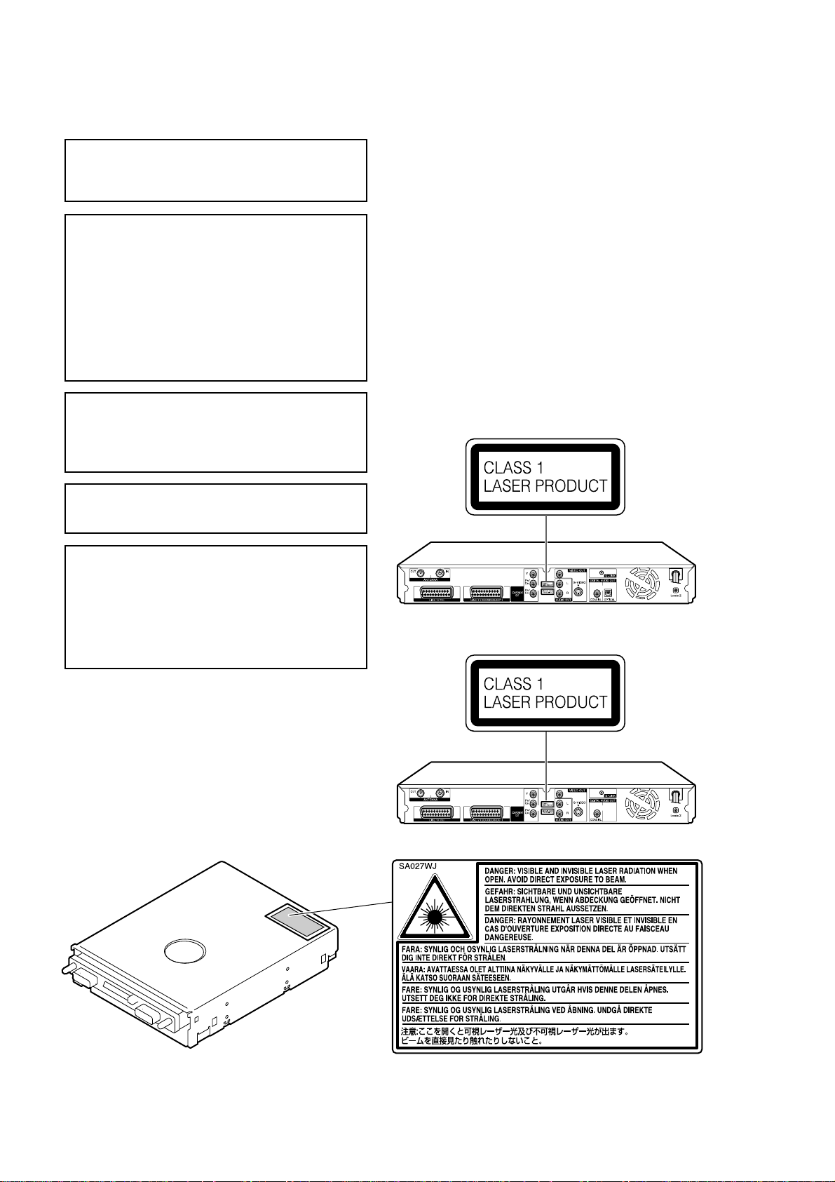
DV-HR400S/H
DV-HR450S/H
DV-HR480S/H
2. FEATURES
1
“DVD Multi-Play” can play 5 types
of recordable DVD discs
•Besides DVD-RW, DVD-R, DVD+RW *
1
and
DVD+R *
1
discs, it can also play DVD-RAM *
2
discs.
Even a DVD borrowed from a friend can be played
no matter what format it uses.
*1
Only the discs recorded in a video format and finalised
can be played.
*2
DVD-RAM Version 2 discs with a 4.7GB or 9.6GB
capacity which have been recorded using the VR system
of another DVD recorder. (To play a DVD-RAM disc,
remove the disc from its cartridge.)
2
Support for high-speed dubbing
*3
at up to 48x speed from the HDD
to DVD makes creating a video
library easy
High speed dubbing*
3
Enables high speed dubbing from hard disc to DVD
so you can enjoy creating your own video library.
Rate conversion dubbing
The mode can be selected from 32 levels just like
recording mode. This enables recording at the
optimal picture quality, given the remaining empty
space on the disc.
Exact dubbing
This automatically adjusts to the optimal record
mode so that the material is dubbed exactly into the
remaining area on the disc.
*3
To perform high-speed dubbing, you must use discs
conforming to Ver.1.1/2x, 1.2/2x or 1.2/4x for DVD-RW, or
Ver.2.0/4x or 2.0/8x for DVD-R. When using DVD-RW
Ver.1.1/2x and DVD-R Ver.2.0/4x, the maximum dubbing
speeds will be approximately 12x and 24x, respectively.
3
Progressive scanning playback
•Using Component Video Output, you can enjoy high
quality, high-density video with no jagged contours
and no flicker.
4
The GUIDE Plus+ system
•The GUIDE Plus+® *
4
system is an interactive on-
screen television programming guide integrated into
the Recorder. The system is available at no monthly
charge and offers programme listings for all major
channels received in your home, one-touch
recording, search by genre, recommendations
according to your profile and more. In this new era
of ever-increasing number of channels, the GUIDE
Plus+ system offers television viewers a convenient
way to find out what's on right now or in the next
week, by channel or by genre. The GUIDE Plus+
system also allows viewers to automatically set
their recording selections quickly and easily. The TV
listings information displayed in the GUIDE Plus+
system is obtained directly from sources in the
broadcasting industry. This information is received
and processed by Gemstar-TV Guide and “broad-
casted”via so called “Host Channels”directly to the
Recorder.
•You can also programme your Recorder for timer
recording simply by inputting the SHOWVIEW®*
4
programming number.
*
4
GUIDE Plus+, SHOWVIEW, VIDEO Plus+, G-LINK are (1)
registered trademarks or trademarks of, (2) manufactured
under license from and (3) subject of various international
patents and patent applications owned by, or licensed to,
Gemstar-TV Guide International, Inc. and/or its related
affiliates.
5
Built-in DV terminal for high
quality dubbing from digital video
camcorder (DV-HR480S/DV-
HR450S only)
•You can connect to a digital video camcorder with
i.LINK to perform high quality digital video dubbing.
You can also operate camcorder playback functions
such as rewind, fast forward, and stop from the
control panel.
6
High picture quality design (Used
in all hard disc and DVD modes)
Progressive scanning playback
High-quality, high-density video with no jagged
contours and no flicker.
VBR (Variable Bit Rate) recording
Constantly maintains optimal high picture quality by
varying the bit rate (amount of video data) for each
scene depending on the video content (e.g.
whether movement is fast or slow).
Improved play noise reduction
3-dimensional DIGITAL NOISE REDUCTION: This
eliminates the noise contained in the brightness
signals and colour signals, and minimizes the rough
textures of images.
BLOCK NOISE REDUCTION: This cuts the amount
of block noise seen in the fast-moving images in
sports programmes, for example.
MOSQUITO NOISE REDUCTION: This reduces the
flicker noise that occurs in areas such as the
outlines of images.
Linear PCM recording
Linear PCM recording with high sound quality is
supported *
5
to reproduce music programmes and
other such programmes with a clear sound quality.
*5
Supports only the XP mode.
The DV-HR480S/DV-HR450S/DV-HR400S DVD Recorder with Hard Disc
realises easy programming with the GUIDE Plus+ system, and up to 48x
high-speed dubbing.
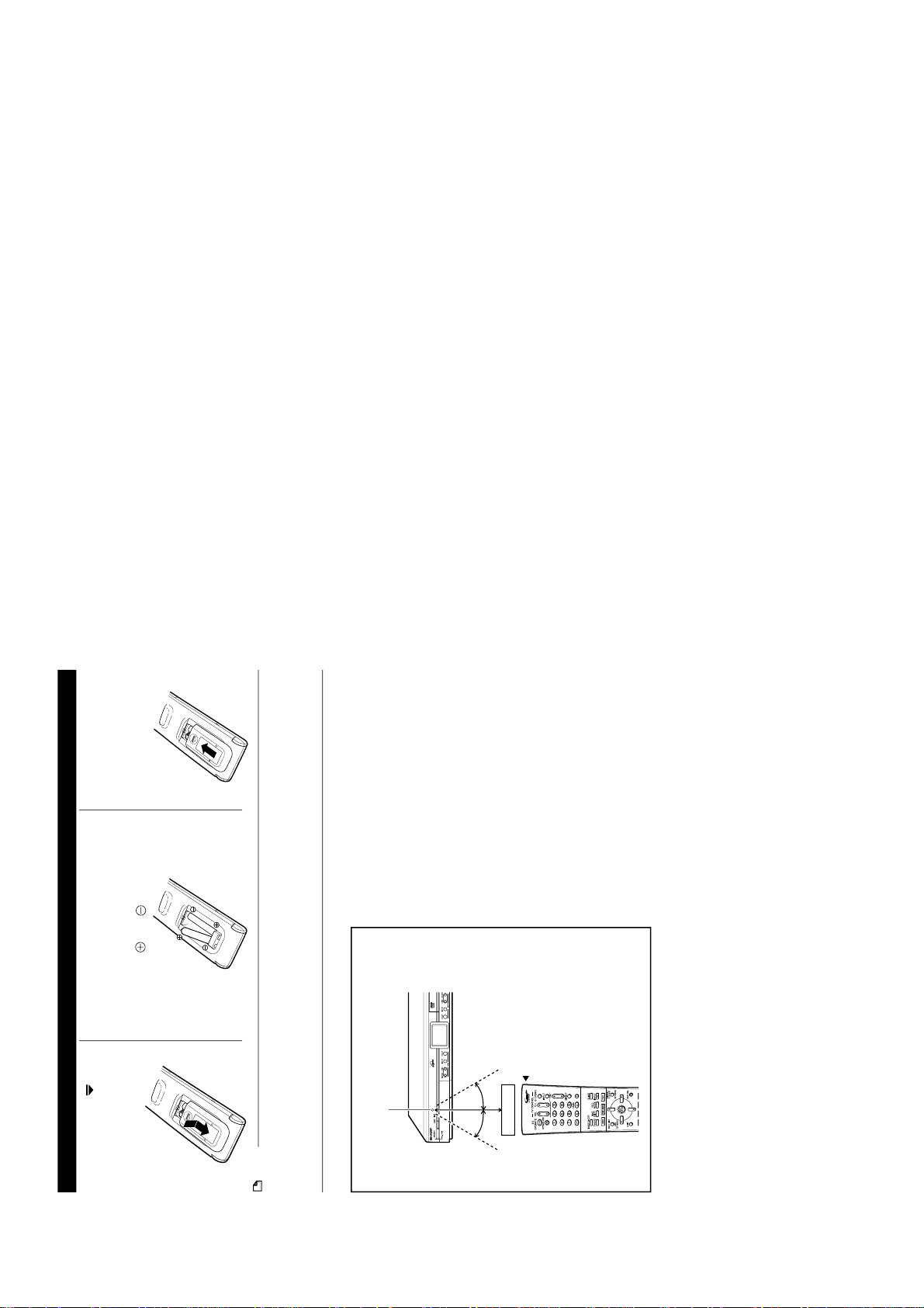
1
2
3
1
2
3
4


 User manual")


 User manual")
 User manual")