manuals.online logo
Brands
  1. Home
  2. •
  3. Brands
  4. •
  5. Sharp
  6. •
  7. Microwave Oven
  8. •
  9. Sharp Carousel RK-42S24 User manual

Sharp Carousel RK-42S24 User manual

This manual suits for next models

4

Other Sharp Microwave Oven manuals

Sharp Carousel SMC1169HS User manual

Sharp

Sharp Carousel SMC1169HS User manual

Sharp SMC1111AB User manual

Sharp

Sharp SMC1111AB User manual

Sharp R-220EW User manual

Sharp

Sharp R-220EW User manual

Sharp R-305CW User manual

Sharp

Sharp R-305CW User manual

Sharp R-92STM User manual

Sharp

Sharp R-92STM User manual

Sharp KB-6015KK User manual

Sharp

Sharp KB-6015KK User manual

Sharp R-860 User manual

Sharp

Sharp R-860 User manual

Sharp R-92A0V User manual

Sharp

Sharp R-92A0V User manual

Sharp R2398JA Use and care manual

Sharp

Sharp R2398JA Use and care manual

Sharp Carousel II R-1820 User manual

Sharp

Sharp Carousel II R-1820 User manual

Sharp KM-2002B User manual

Sharp

Sharp KM-2002B User manual

Sharp R-318BK User manual

Sharp

Sharp R-318BK User manual

Sharp SMO1854DS User manual

Sharp

Sharp SMO1854DS User manual

Sharp Carousel R-1520L Use and care manual

Sharp

Sharp Carousel R-1520L Use and care manual

Sharp R-1514F User manual

Sharp

Sharp R-1514F User manual

Sharp R-898M User manual

Sharp

Sharp R-898M User manual

Sharp R-G221VN User manual

Sharp

Sharp R-G221VN User manual

Sharp R-398K User manual

Sharp

Sharp R-398K User manual

Sharp R-890E W Installation manual

Sharp

Sharp R-890E W Installation manual

Sharp Microwave Drawer SMD2443JSC User manual

Sharp

Sharp Microwave Drawer SMD2443JSC User manual

Sharp R-8000G User manual

Sharp

Sharp R-8000G User manual

Sharp R-239 Instruction Manual

Sharp

Sharp R-239 Instruction Manual

Sharp R-754M Instruction Manual

Sharp

Sharp R-754M Instruction Manual

Sharp Carousel R-980E User manual

Sharp

Sharp Carousel R-980E User manual

Popular Microwave Oven manuals by other brands

PROFILO MD1000 instruction manual

PROFILO

PROFILO MD1000 instruction manual

Candy MIC 201 EX User instructions

Candy

Candy MIC 201 EX User instructions

PITSOS GMW3101B user manual

PITSOS

PITSOS GMW3101B user manual

Sears 5648744780 Use & care manual

Sears

Sears 5648744780 Use & care manual

BOMANN CB 1272 Instruction manual & guarantee

BOMANN

BOMANN CB 1272 Instruction manual & guarantee

Conrad Electronic 2372935 operating instructions

Conrad Electronic

Conrad Electronic 2372935 operating instructions

GE Spacemaker JVM1440BH datasheet

GE

GE Spacemaker JVM1440BH datasheet

DAEWOO ELECTRONICS KOR-6L8K5S83 Operating instructions & cook book

DAEWOO ELECTRONICS

DAEWOO ELECTRONICS KOR-6L8K5S83 Operating instructions & cook book

DAEWOO ELECTRONICS KOR-1N5A9S Operating instructions & cook book

DAEWOO ELECTRONICS

DAEWOO ELECTRONICS KOR-1N5A9S Operating instructions & cook book

Daewoo KQG-6617G Operating instructions & cook book

Daewoo

Daewoo KQG-6617G Operating instructions & cook book

Samsung M1779 Owner's instructions

Samsung

Samsung M1779 Owner's instructions

GE JES1143 Use and care & cooking guide

GE

GE JES1143 Use and care & cooking guide

Miele H6200BM(TB) Operating and installation instructions

Miele

Miele H6200BM(TB) Operating and installation instructions

Jocel JMO011480 instruction manual

Jocel

Jocel JMO011480 instruction manual

Electrolux EVL8E00X user manual

Electrolux

Electrolux EVL8E00X user manual

STOVES Q900GRF DO User, installation & servicing instructions

STOVES

STOVES Q900GRF DO User, installation & servicing instructions

Daewoo KOR-6L0B3S Operating instructions & cook book

Daewoo

Daewoo KOR-6L0B3S Operating instructions & cook book

KitchenAid KCMS1555 Use and care guide

KitchenAid

KitchenAid KCMS1555 Use and care guide

manuals.online logo
manuals.online logoBrands
  • About & Mission
  • Contact us
  • Privacy Policy
  • Terms and Conditions

Copyright 2025 Manuals.Online. All Rights Reserved.

1
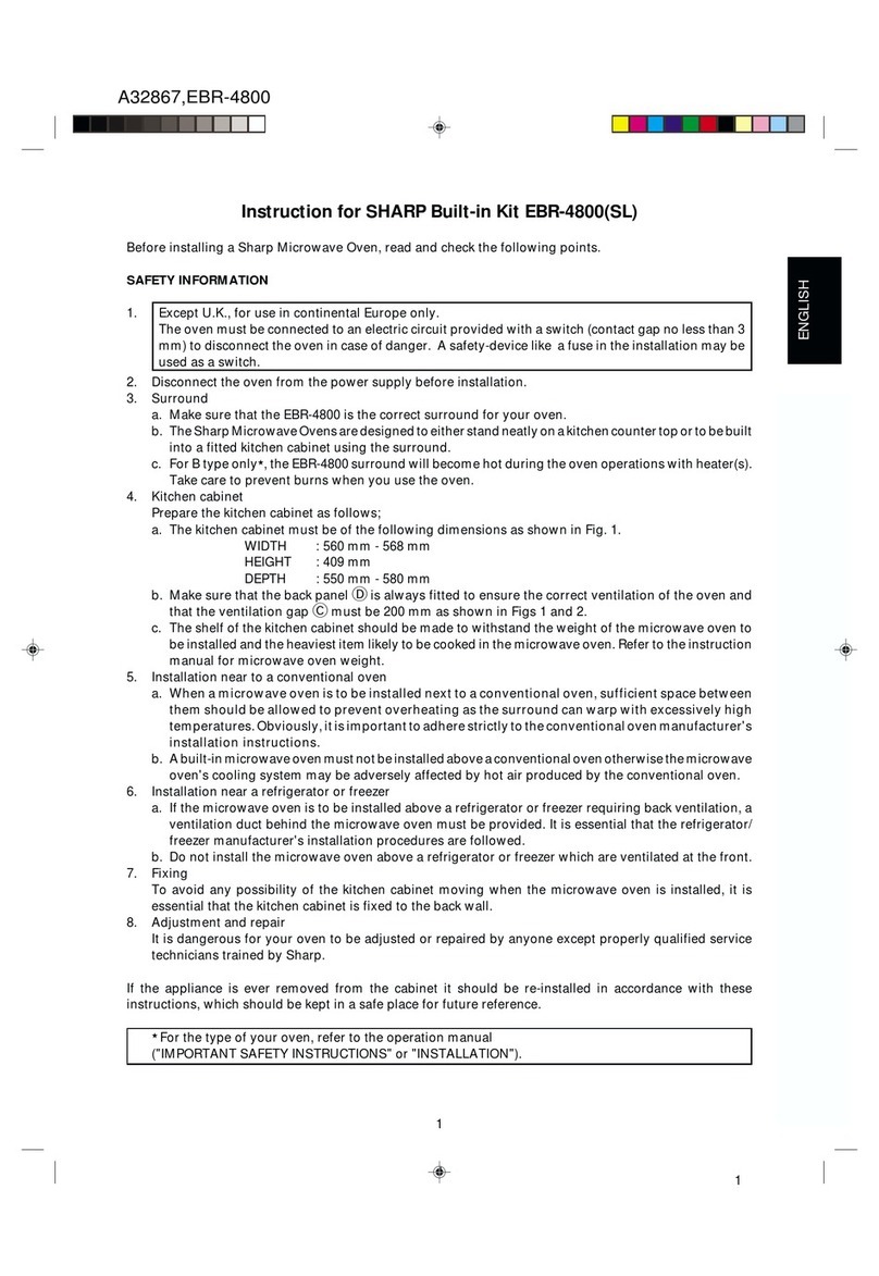
For Sharp Carousel®Built-in Kit
Models RK-42S24, RK-51S27,
RK-51K30, RK-51S30 or RK-51W30.
THIS KIT IS UL APPROVED TO ALLOW CERTAIN MICROWAVE OVENS
TO BE INSTALLED ABOVE CERTAIN CONVENTIONAL/CONVECTION
WALL OVENS. PLEASE SEE THE OPERATION MANUAL REGARDING
APPROVED BUILT-IN APPLICATIONS.
INSTALLATION INSTRUCTIONS
3
®
12
4567
NO. PART NAME QTY
PART CODE
1FRAME ASSEMBLY 1
S24 - FDECAB015MRY0
S27 - FDECAB008MRY0
S30 - FDECAB018MRY0
K30 - FDECAB019MRY0
W30 - FDECAB020MRY0
2EXHAUST DUCT ASSEMBLY 1
S24 - FDUC-B019MRK0
S27 - FDUC-B032MRK0
S30 - FDUC-B032MRK0
K30 - FDUC-B032MRK0
W30 - FDUC-B032MRK0
3POWER SUPPLY CORD 1
BOX ASSEMBLY
FCOVHB004MRK0
4REAR DUCT 1
PDUC-B072MRP0
5SCREW A 3
XCTSD40P10000
6SCREW B 2
XTTSD40P30000
7SCREW C 4
S24 - LX-CZB012MRE0
S27 - LX-CZB012MRE0
S30 - LX-CZB012MRE0
K30 - LX-CZB014MRE0
W30 - LX-CZB015MRE0
IMPORTANT:
This Built-in Kit is designed for and approved only for those Sharp
Microwave Ovens specifyingBuilt-InKitRK-42S24,RK-51S27, RK-51K30,
RK-51S30 or RK-51W30 on the rating label on the left side wall of the
oven cavity.
The cabinet or wall opening must be within the following dimensions:
RK-42S24 HEIGHT : 15 11/16" to 16"
WIDTH : 22 1/16" to 22 3/8"
DEPTH : minimum 19 1/4"
*RK-51S27, *RK-51K30, HEIGHT : 16 3/4" to 17"
*RK-51S30 & *RK-51W30 WIDTH : 24 3/8" to 24 11/16"
DEPTH : minimum 20"
*IFYOURLOWERCONVENTIONALOVENISNOT LISTEDINTHEOPERATIONMANUALOF
THE MICROWAVE OVEN AS AN APPROVED MAKE AND MODEL, THEN DO NOT INSTALL
THE MICROWAVE OVEN ABOVE IT OR IN ANY AREA WHERE HEAT AND STEAM ARE
GENERATED; FOR EXAMPLE, NEXT TO OR ABOVE A CONVENTIONAL RANGE.
S= Stainless, K=Black, W=White
PLEASE READ THESE INSTRUCTIONS THOROUGHLY BEFORE
BEGINNING INSTALLATION!
•Be sure to DISCONNECT THE PLUG of the microwave oven from the
electrical outlet before installing the Built-in Kit. Remove the Carousel
turntable from the oven cavity.
•Because the kit includes metal parts, due caution should be used in
handling and installation to avoid the possibility of injury.
2
C
4"
4" 6"
RK-42S24:
HEIGHT : 16 3/4" to 17"
WIDTH : 24 3/8" to 24 11/16"
DEPTH : minimum 20"
HEIGHT : 15 11/16" to 16"
WIDTH : 22 1/16" to 22 3/8"
DEPTH : minimum 19 1/4"
*RK-51S27,
*RK-51K30,
*RK-51S30&
*RK-51W30
1. Place the EXHAUST DUCT ASSEMBLY in the
opening. When the EXHAUST DUCT ASSEMBLY
is in the opening correctly, its flanges will be tightly
against the lower edge of the opening. See
Sketch 2.
2. Secure the EXHAUST DUCT ASSEMBLY with two
SCREWS B. See Sketch 2.
Sketch 1
Sketch 2
A
B
STEP 2 EXHAUST DUCT ASSEMBLY INSTALLATION
STEP 1 CABINET OR WALL OPENING
SCREW B
SCREW B
EXHAUST
DUCT ASSEMBLY
The opening in the wall or cabinet must be within the
following dimensions:
Outlet should NOT be in the shaded area as indicated
on Sketch 1.
NOTE 1: If the dimension of DEPTH (C) is more than
21", the outlet location may be any area on the
rear wall.
NOTE 2: Thefloor of the opening should be constructed
of plywood strong enough to support the
weight of the oven and floor load (about 100
pounds). The floor should be level for proper
operation of the oven. Be sure to check the
local building code as it may require that the
opening be enclosed with sides, ceiling and
rear partition. The proper functioning of the
oven does not require the enclosure.
3
STEP 3 POWER SUPPLY CORD BOX ASSEMBLY AND REAR DUCT INSTALLATION
1. Roll the power supply cord into the REAR DUCT.
2. Remove the screw ✪from left top of outer
cabinet. Secure the left flange of the REAR
DUCT with the screw ✪removed from the oven
and secure the right flange of the REAR DUCT
with SCREW A. See Sketch 3.
3. Plug the oven power supply cord into the
POWER SUPPLY CORD BOX ASSEMBLY
receptacle. See Sketch 4.
4. Slide the POWER SUPPLY CORD BOX
ASSEMBLY into the REAR DUCT and secure
the POWER SUPPLY CORD BOX ASSEMBLY
and REAR DUCT with two SCREWS A. See
Sketch 5. SCREW A
Sketch 3
REAR DUCT
✪
POWER SUPPLY
CORD BOX ASSEMBLY
Sketch 4
Sketch 5
REAR DUCT
SCREW A
POWER SUPPLY
CORD BOX ASSEMBLY
SCREW A
4
STEP 4 FRAME INSTALLATION
1. Placethe ovenadjacent tothewallorcabinet opening.Plugthe POWER
SUPPLY CORD BOX ASSEMBLY cord into the electrical outlet.
2. Carefully guide the assembled oven into the prepared opening. Slide
the oven on the EXHAUST DUCT ASSEMBLY. See Sketch 6. Avoid
pinching the cord between the oven and the wall.Adjust the position of
the oven so that the feet of the oven are fitted into the recesses of the
EXHAUST DUCT ASSEMBLY. See Sketch 7.
3. Position the FRAME ASSEMBLY to be square with the oven. Carefully
place the FRAME ASSEMBLY on the oven. Check that it is level and
then secure with two SCREWS C. See Sketch 8.
4. Secure the bottom portion of the FRAME ASSEMBLY with the two
remaining SCREWS C. See Sketch 8.
SHARP ELECTRONICS CORPORATION
Sharp Plaza, Mahwah, New Jersey 07430-2135 TINSEB279MRR0
Printed in U.S.A.
Sketch 6
FOOT
POWER SUPPLY CORD BOX
ASSEMBLY
RECESS
REAR DUCT ASSEMBLY
Sketch 7
EXHAUST DUCT ASSEMBLY
Sketch 8
For any other assistance or information about this kit, please call
Sharp’s Customer Assistance Center at
1-800-BE-SHARP (1-800-237-4277)
SCREW C
SCREW C
SCREW C
SCREW C
OVEN