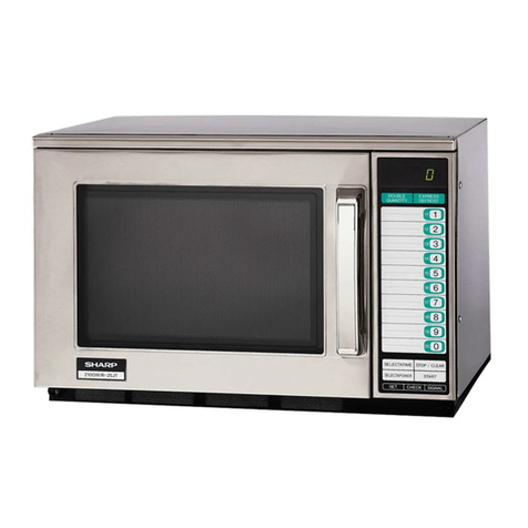
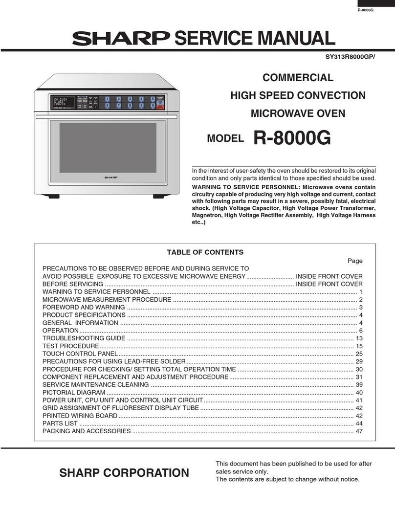
Sharp R-2380 User manual

SHARP SERVICE MANUAL
S5001 R2380J//
COMMERCIAL
MICROWAVE OVEN
MODEL R-2380
In interests of user-safety the oven should be restored to its original
condition and only manufacturer original spare parts must be used.
TABLE OF CONTENTS Page
CAUTION, MICROWAVE RADIATION .......................................................................................................... 1
GENERAL IMPORTANT INFORMATION ...................................................................................................... 1
WARNING .......................................................................................................................................................... 1
PRODUCT SPECIFICATIONS ......................................................... ................................................................ 2
APPEARANCE VIEW ........................................................................................................................................ 3
OPERATING SEQUENCE ................................................................................................................................. 4
FUNCTION OF IMPORTANT COMPONENTS .............................................................................................. 7
COUNTER CHECK ............................................................................................................................................ 9
RESETTING THE COUNTER MEMORIES .................................................................................................. IO
SERVICING ..................................................................................................................................................... 15
TEST PROCEDURE ........................................................................................................................................ 20
TOUCH CONTROL PANEL ........................................................................................................................... 28
COMPONENT REPLACEMENT AND ADJUSTMENT PROCEDURE ..................................................... 39
MICROWAVE MEASUREMENT ................................................................................................................... 46
TEST DATA AT A GLANCE ....................................................... ................................................................... 47
TEST POINT ON CONTROL UNIT ............................................................................................................... 47
WIRING DIAGRAM ....................................................................................................................................... 48
PICTORIAL DIAGRAM .................................................................................... -.............................................. 49
CONTROL PANEL CIRCUIT ......................................................................................................................... 50
PRINTED WIRING BOARD .......................................................................................................................... 51
SPARE PARTS LIST ...................................................................................................................................... 52
SHARP CORPORATION

R-2380

R-2380
SERVICE MANUAL
SHARP
COMMERCIAL
MICROWAVE OVEN
R-2380
FOREWORD
This Manual has been prepared to provide Sharp Corp. Service
Personnel with Operation and Service Information for the
SHARP MICROWAVE OVEN R-2380.
It is recommended that service personnel carefully study the
entire text of this manual so they will be qualified to render
satisfactory customer service.
Check interlock switches and door seal carefully. Special at-
tention should be given to avoid electrical shock and micro-
wave radiation hazard.
CAUTION
MICROWAVE RADIATION
Personnel should not be exposed to the microwave energy
which may radiate from the magnetron or other microwave
generating devices if it is improperly used or connected. All
input and output microwave connections, waveguides, flanges
and gaskets must be secured. Never operate the device without
a microwave energy absorbing load attached. Never look into
an open waveguide or antenna while the device is energized.
Note( Parts List) : The parts marked rr*rr are used in voltage
more than 250V.
SHARP CORPORATION
OSAKA, JAPAN
1
..(‘i’ ((
,’
_ \s,- ..‘<\.,~ _-
.(_ .,I,?. ., -> f ,..
\
). -. .., :, : 4 $
: PRODUCT SPECIFICATIONS
-rt
“-‘: OPERATING SEQUENCE
: .; FUNCTION OF IMPORTANT ’
-, i _ : , ,’
~.,COMPONENTS
: i “” :I
,;.,-..;;;__;r TROUBLESHOOTING CHART
_ .,=-
. ‘...T
,, ‘:‘ TEST PROCEDURE
.~*
; j:! ASSEMBLY ” .
/ _i
j. .c$ MICROWAVE MEASUREMENT
*l
i * .*
*w*-=>-* I I ‘?“~~~~~~~~i~.~~~~~~*~ a~~~~r$g~;*w
j -,- -.+vaz*~4h~&~* ~..,~~~~~~~~~~~~~~
‘; ” ~&,,&~,$;g ,-,* ,:.*:+ ,, -‘F :I: :.!
. - ,” I
.: >. _. I, * **.*q- * “‘“~~~~~,~~~~~~‘~~~~.
_ _~ .~&$&&&&,@ -,t~~~~~.~~~~~~~~~~~~~~~-~ :’
” _.,_ yp,‘.” i ,_* __ a_,_ 37,j,e.-* 1B, 5 cr*i,*r
;:$,,;.;.l$j TEST DATA TABLE AND
-* :%TEST POINTS ON CONTROL
I ..z
“<<*~.,qE‘*5*““: _i
g.:
:j:
4 :
,;I+ PRINTED WIRING BOARD
- PARTS LIST

PRODUCT DESCRIPTION
SPECIFICATION
ITEM
Power Requirements
--
Power Consumption
Power Output
Outside Dimensions
Cooking Cavity Dimensions
Control Complement
Set Weight
DESCRIPTION
240 Volts
50 Hertz
Single phase, 3 wire earthed
Microwave cooking 2.4 kW Approx. 10.0 A
1300 watts nominal of RF microwave energy (2 litter water load)
Operating frequency of 2450MHz
Width 510 mm
Height 335 mm including foot
Depth 415 mm
Width 330 mm
Height 210 mm
Depth 310 mm
Touch Control System
Microwave power level
100% 90% 80% 70% 60% 50%
40% 30% 20% 10% 0%
MANUAL TIME SET key
MICROWAVE POWER SETTING key
STOP/CLEAR key
START key
DOUBLE QUANTITY key
/ EXPRESS DEFROST key
SET key
CHECK key
VOLUME key
Approx. 30.0 kg
Your oven can be programmed a series of up to 2 cooking stages.
r The combination of microwave power and cooking time that can be input is as follows.
Cooking ‘Sequence
2 stage
cooking
2 stage
cooking
2 stage
cooking
1•j first stage
q second stage 1 30
2 stage q first stage 15
cooking q second stage 15
IThe combination of cookinq time & microwave power I
10 15 20’ 25 30 35 40 45 50 55 $0
n.
2

R -2380
GENERAL INFORMATION
WARNING
THIS APPLIANCE MUST BE EARTHED
IMPORTANT
THE WIRES IN THIS MAINS LEAD ARE COLOURED IN ACCORDANCE WITH THE FOLLOWING CODE:
GREEN-AND-YELLOW : EARTH
BLUE : NEUTRAL
BROWN : LIVE
APPEARANCE VIEW
L*+
YLECTATME enter 11”w
Fa “Ma lOox sELECTwowER
e&ynbn la wxnlws
I j 6 1
I I 7 1
I ! 9 I
I
/ iol
@j-j SELECTATIME11STOPKLEARpj$
@$-fGq,,,b
8--Ts;f7 CHECKpLGq-@
7
1. Door handle.
2. Access cover for oven lamp
replacement.
3. Oven lamp.
4. Ventilation openings.
5. Waveguide cover.
6. Touch control panel.
7. Safety door latches.
8. Air intake opening and filter.
9. Ceramic shelf.
IO. Hinges.
11. See-through door.
12. Power supply cord.
13. Mounting plate.
14. TIME display: Lighted digital display
up to 60 minutes.00 seconds.
15. Cooking indicator.
16. SELECTAPOWER display;
percentage of microwave power is
indicated.
17. DOUBLE QUANTITY pad.
18. EXPRESS DEFROST pad.
19. Ten NUMBER pads for time and
memory programming.
20. SELECTATIME pad.
21. SELECTAPOWER pad for setting
variable power level.
22. STOP/CLEAR pad; touch to stop
operation of oven and clear
remaining cooking time.
23. START pad. Touch to operate
oven afler door is closed and time
is set.
24. SET pad for setting memory.
25. CHECK pad for checking memory.
26. VOLUME pad for setting sound
level.
I
3

OPERATING SEQUENCE
OFF CONDITION 4.
Closing the door activates all door interlock switches
(Upper latch switch, lower latch switch and stop
switch)
IMPORTANT 5.
When the oven door is closed, the monitor switch
contacts COM-NC must be open.
When the microwave oven is pluged in a wall outlet
(240 volts, 50Hz), the line voltage is supplied to the
point A5+ A7 in the control panel.
Figure O-1 on page 48
The display shows 1-I.
NOTE: When the door is opened or after cooking,
oven lamp and blower motor operate for 1
minute.
MICROWAVE COOKING CONDITION
Touch SELECTATIME key and enter a desired cooking
time with the touching NUMBER key. And then touch
START key.
Function sequence Figure O-2 on page 48
CONNECTED COMPONENTS
Oven lamp / Blower motor
Power transformer Tl
Power transformer T2
RELAY
RYI
RY3
RY4
6.
s-l-en the oven door is opened during or after the
1. The line voltage is supplied to the primary winding
of the power transformer. The voltage is converted
to about 3.3 volts A.C. output on the filament
winding and high voltage of approximately 2000
volts A.C. on the secondary winding.
2. The filament winding voltage (3.3 volts) heats the
magnetron filament and the high voltage (2000
volts) is sent to the voltagedoubling circuit, where
it is doubled to negative voltage of approximately
4000 volts D.C..
6-2.
3. The 2450 MHz microwave energy produced in the
magnetron generates a wave length of 12.24 cm.
This energy is channeled through the waveguide
(transport channel) into the oven cavity, where the
food is placed to be cooked.
6-3.
4
When the cooking time is up, a signal tone is heard
and the relays RY3+ RY4 go back to their home
position. The circuits to the power transformers
Tl + T2 are cut off.
The relay RY1 remains and oven lamp and blower
motor operate for 1 minute.
When the door is opened during a cook cycle, the
switches come to the following condition,
CONDITION
DURING DOOR OPEN
SWITCH CONTACT COOKING (NO COOKING)
Upper latch switch COM-NO Closed ODen
Monitor switch COM-NC Open Closed
Lower latch switch COM-NO Closed Open
Stop switch COM-NO Closed Open
The circuits to the power transformers Tl + T2 are
cut off when the upper latch, lower latch and stop
switches SW1 + SW2+ SW4 are made open. The
blower motor .B& and oven lamp remain on even if
the oven door is opened after the cooking cycle has
been interrupted, because the relay RY1 stays
closed. Shown in the display is the remaining time,
but the program is cancelled if the oven is not
started within 3 minutes.
MONITOR SWITCH CIRCUIT
The monitor switch SW3 is mechanically controlled
by oven door, and monitors the operation of the
upper latch switch sw1 and lower latch switch
SW2
cycle of a cooking program, the upper latch, lower
latch and stop switches SW1 + SW2+ SW4 must
open their contacts first. After that the contacts
(COM- NC) of the monitor switch SW3 can be
closed.
When the oven door is closed, the contacts
(COM-NC) of the monitor switch SW3 must be
opened first. After that the contacts (COM -NO)of
the upper latch. lower latch and stop switches
SW1 + SW2+ SW4 must be closed.
When the oven door is opened and the contacts
of the upper latch switch SW/J and lower latch
switch SW2 remain closed, the fuse F3 BSF 13A
will blow, because the monitor switch is closed
and a short circuit is caused.
R-2380
TWO MAGNETRON OPERATION SYSTEM
Two magnetrons MGl + MG2 are equipped in order to get higher microwave power output.
The primary windings of the power transformers Tl + T2 are connected so that each magnetron can be oscillated
alternatively according to the frequency of the power supply. Refer to the Figure 1 and 2.
\
T2: POWER TRANSFORMER
r-----7
Tl: POWER TRANSFORMER
r---+J=f---
0: H. V. RECTIFIER C2: tZ~;P&ITOR
AC2:OO”
ASYMMETRIC
RECTIFIER
U
0: H.V. RECTIFIER Cl: CAPACITOR
0.87pf
AC2IOOV
.
Figure 1. High Voltage Circuit
COMMERCIAL
FREQUENCY
150Hz)
POWER OUTPUT
BY MAGNETRON 1 Y
A Ezl OPERATION OF
I MAGNETRON
POWER OUTPUT
BY MAGNETRON 2
Figure 2. Operation of Magnetron
5
-

MICROWAVE VARIABLE COOKING
When the microwave oven is preset for variable cooking power, the line voltage is supplied to the power transformers
Tl + T2 intermittently within a 32 second time base through the contacts of the relays RY3+ RY4.
The following levels of microwaves power are given.
Number key
Number key 9
Number key 8
Number key 7
Number key 6
Number key 5
Number key 4
Number key 3
Number key 2
Number key 1
Number key 0
30 set ON
26 set ON
24 set ON
22 set ON
18 set ON
16 set ON
12 set ON 1
8 set ON
6 set ON
0 set ON
NOTE: The ON/OFF time ratio does not exactly correspond to the percentage of microwave power, because
aoprox. 2 seconds are needed for heating up the magnetron filament.
6

FUNCTION OF IMPORTANT COMPONENTS
UPPER LATCH SWITCH SW1
LOWER LATCH SWITCH SW2
STOP SWITCH SW4
SW1 + SW2 + SW4
1. When the oven door is
COM-NO must be closed.
2. When the oven door is
COM-NO must be opened.
MONITOR SWITCH SW3
closed, the contacts
opened, the contacts
The monitor switch is activated (the contacts opened)
by the upper latch head and switch lever A while the
door is closed. The switch is intended to render the
oven inoperative by means of blowing the fuse B BSF
13A when the contacts of the upper latch switch sw1
and lower latch switch SW2 fail to open when the door
is opened.
Function
1. When the door is opened, the monitor switch SW/J
contacts close (to the ON condition) due to their
being normally closed. At this time the upper latch
switch $IV’J and lower latch switch SW2 are in the
OFF condition (contacts open) due to their being
normally open contact switches.
2. As the door goes to a closed position, the monitor
switch contacts are opened and upper latch switch
sw1 and lower latch switch SWJ contacts are
closed (On opening the door, each of these
switches operate inversely.)
3. If the door is opened and the upper latch switch
SW’J and lower latch switch SW2 contacts fail to
open, the fuse FJ BSF 13A blows simultaneously
with closing of the monitor switch contacts.
CAUTION: BEFORE REPLACING A BLOWN FUSE
FJ BSF 13A TEST THE UPPER LATCH
SWITCH, LOWER LATCH SWITCH,
MONITOR SWITCH AND MONITOR RE-
SISTOR FOR PROPER OPERATION.
(REFER TO CHAPTER “TEST PROCE-
DURE”).
MONITOR RESISTOR
The monitor resistor prevents the fuse FJ BSF 13A
bursting when the fuse FJ BSF 13A blows due to the
operation of the monitor switch.
ASYMMETRIC RECTIFIER
The asymmetric rectifier is solid state device that pre-
vents current flow is both directions. And it prevents
the temperature rise of the power transformer by
blowing the fuse M8A Fl or F2 when the high voltage
rectifier is shorted.
The rated peak reverse voltage of Dl of the asymmetric
rectifier is 6 KV The rated peak reverse voltage of D2
of the asymmetric rectifier is 1.7 KV. Dl and D2 of the
asymmetric rectifier or high voltage rectifier are shorted
when the each peak reverse voltage goes beyond the
each rated peak reverse voltage. (The process of the
blowing the fuse M8A Fl or F2)
1.
2.
3.
4.
5.
6.
7.
The high voltage rectifier is shorted by any causes
when microwave cooking.
The peak reverse voltage of D2 of the rectifier goes
beyond the rated peak reverse voltage 1.7 KV in the
voltage doubler circuit.
D2 of the rectifier is shorted.
The large electric currents flow through the high
voltage winding of the power transformer.
The large electric currents beyond 8A flow through
the primary widing of the power transformer.
The fuse Fl or F2 blows by the large electric cur-
rents.
The power supplying to the power transformer is
cut off. And the control panel will display
( EE-1 ), ( EE-2 ), ( EE-3 ).
FUSE BSF 13A 250V F3
1. If the wire harness or electrical components are
short-circuited, this fuse blows to prevent an elec-
tric shock or fire hazzard.
2. The fuse also blows when upper latch switch sw1
and lower latch switch SW2 remain closed with the
oven door open and when the monitor switch SW3
closes.
THERMISTOR
The thermistor is a negative temperature coefficient
type. The temperature in the exhaust duct is detected
through the resistance of the thermistor.
If the temperature rises about 12O”C, the control panel
will display ( EE - 7 ) and the oven will stop to avoid
overheating an catching fire.
7

:-2380
BLOWER MOTOR BM
The blower motor drives a blade which draws external
cool air. This cool air is directed through the air vanes
surrounding the magnetrons and cools the magnetrons.
This air is channeled through the oven cavity to remove
steam and vapors given off from the heating foods. It
is then exhausted through the exhausing air vents at
the oven cavity.
MG THERMAL CUT-OUTS 145°C TCI, TC2
These thermal cut-outs protect the magnetrons against
overheat. If their temperature go up higher than
145°C because the blower motor is interrupted, the
ventilation openings are blocked, the thermal cut-outs
TCl + TC2 will open and the line voltages to the
power transformer Tl + T2 will be cut off and the op-
erations of the magnetrons MGI + MG2 will be
stopped.
The thermal cut-outs TCl + TC2 will close their con-
tacts again when their temperatures go down lower
than - 20°C.
BLOWER MOTOR THERMAL CUT-OUT 115°C
TC3
This thermal cut-out protect the blower motor against
overheat. If its temperature goes up higher than
115°C because the blower motor is locked or the ven-
tilation openings are blocked, the contacts of the ther-
mal cut-out TC3 will open and the line voltage to the
control unit will be cut off and the operation of the
oven will be stopped.
The thermal cut-out TC3 will be close its contacts
again when its temperature goes down lower than
- 20°C.
OVEN TEMP. FUSE 150°C TF
This temp. fuse protects the oven against overheat. If
the temperature goes up higher than 150°C because
the food catches fire, the contacts of temp. fuse E will
open and the line voltage to the control unit will be cut
off and the operation of the oven will be stopped. The
defective temp. fuse must be replaced with a new rated
one.
8
DOOR OPEN MECHANISM
1. The door release lever is pulled.
2. The upper latch head is lifted up by the linked door
release lever.
3. The latch lever is lifted up by the door release lever.
4. The joint lever is lifted up by the latch lever.
5. The lower latch head is lifted up by the joint lever.
6. Now both latch heads are lifted up, so they can be
released from the latch hook.
7. Now the door can be opened.
Door release _
lever
..-..-
._
i
1 \
‘..
/
r’/ Latch head
-._
Latch lever
Monitor
switch
Latch
hook
Lower latch switch
Figure D-l .Door Open Mechanism

R-2380
Counter Check
;tep Procedure Order Display
Touch START pad for 2 seconds.
1 w
After 2 sec. an entry signal il
sounds.
Touch CHECK pad for 2 seconds. pi-j llyvllr*i.
(For 2 sec.)
2 After 2 seconds. m
(Total times used)
Touch NUMBER pad II. El p-y--q
(Times of using memory 1)
Touch SELECTATIME pad.
3
pizGq /I
(Times of manual cooking)
Touch EXPRESS DEFROST pad. l--EEq jl
(Times of EXPRESS DEF-
ROST cooking)
Although the owner can clear all memories (including total times used), the total times the oven has been used
since the last service are retained in the memory. To recall this information carry out the procedure as outlined
in the below.
Carry out steps 1 and 2 above. Then press
3 the SET, VOLUME and START pads.
Y
9’

Resetting the counter memory
When the counter memory is displayed on the readout (see page 9 Counter Check), the count can be reset
to zero by touching the SELECTAPOWER pad for 2 seconds
To reset memory 1 to zero.
itep Procedure Order
Touch START pad for 2 seconds. rxz---j
1 (For 2 sec.)
After 2 sec. an entry signal
sounds.
Touch CHECK pad for 2 seconds. ICHECK
(For 2 sec.)
Touch NUMBER pad II. I 1
Touch SELECTAPOWER pad for 2
seconds. pGq
(For 2 sec.)
4 (After 2 seconds.)
Display
I
WIJYRER CHECK
(Total times used)
(Times of using memory 1)
m 1. To cancel Counter Check modes, touch STOP/CLEAR pad.
2. To clear times of manual cooking, touch SELECTATIME pad at Step 3 instead of NUMBER pad.
To clear times of EXPRESS DEFROST cooking, touch EXPRESS DEFROST pad at Step 3 instead
of NUMBER pad.
3. To clear total using times, skip Step 3.
RESETTING SERVICE COUNT
Carry out steps 1 and 2 above. Then press El
CHECK
3 the SET, VOLUME and START pads. I
VOLUME
Touch SELECTATIME pad. jl
(For 2 sec.)
4 (After 2 seconds.)
10
1 986~ /
0
!-----v

One or two stage cooking can be programmed into any of the 10 programme positions.
To programme the time and power level into a memory
l Suppose you wish to enter 4 minutes at 60% for a single quantity in the memory 1
itep Procedure
Touch START pad for 2 seconds.
1
2 Touch NUMBER pad II.
3 Touch SELECTATIME pad.
4 gh NUMBER pads 141 , 101 and
5 Touch SELECTAPOWER pad.
Order Display
Ez I’
After 2 sec. an entry signal
sounds. I
6 Touch NUMBER pad 161. I6
NOTE: This machine would have been preset to suit the owner’s requirements. If you alter any memory set-
tings during the service please notify the owner when the oven is returned.
MEMORY CHECK
l Suppose you want to know the information programmed into the memory 1, programmed for 4 minutes at 60%
IStepI Procedure
Touch START pad for 2 seconds.
1
2 Touch CHECK pad.
I I
3 Touch NUMBER pad m
J
After 2 sec. an entry signal
11

To change the time constant for double quantity
The time constant for double quantity is preset 1.8 times the single quantity cooking time, but you can alter
this constant to suit your needs.
l Suppose you wish to alter the time constant to 1.67 in memory 1.
-
;tep Order Display
Touch START pad for 2 seconds. 1 START 1
(For 2 sec.)
After 2 sec., an entry signal
sounds.
1
2
-
3
4
5
6
Touch DOUBLE QUANTITY pad for 2
seconds.
1 NUMBER I
(For 2 sec.)
After 2 sec. an entry signal
sounds.
El
1
Touch NUMBER pad II.
Touch SELECTATIME pad. !
‘“‘r::j
I I
J
NUMBER pads /1 , 161 and mm171
Touch SET pad. El
SET
L
DOUBLE QUANTITY CONSTANT CHECK
Suppose you wish to know the double quantity constant entered into programme 1.
Order Display
tep Procedure
I
START
Touch START pad for 2 seconds.
1 (For 2 sec.)
After 2 sec., an entry signal
sounds.
NUMBER CHECK
Touch CHECK pad.
3
I”“‘y,‘“‘”
I’“‘::1
Touch DOUBLE QUANTITY pad.
3
/ 1
4 Touch NUMBER pad )1
12

R-2330
EXPRESS DEFROST
To set te constants of Express Defrost to factory setting:
1st sequence: 20% of total time at 40% power.
2nd sequence: 30% of total time at 30% power.
3rd sequence: 50% of total time at 20% power.
itep Procedure Order Display
Touch START pad for 2 seconds.
1 !izz i
After 2 sec. an entry signal
sounds.
2 Touch SET pad.
m 1”“___1
3 Touch START pad. /I r”-l
4 Touch EXPRESS DEFROST pad. l---EEq v”il
5
Touch SELECTATIME pad. LIEffEl v
6 Touch NUMBER pads /21, 101 mm VI
7 Touch SELECTATIME pad. piizz-j v”‘D1
8 Touch NUMBER pad 121. El /I
9 Touch SELECTAPOWER pad. I
Continued on page 14.
13

EXPRESS DEFROST
--_. ._--- __. ..-
Step Procedure Order Display
Touch NUMBER pad 141.
10 El -1
Touch SELECTATIME pad.
11 LEEEEl p-x&--j
12
Touch NUMBER pads a, 131. mEr /r0-‘i3
Touch SELECTATIME pad.
13 pzEq v\
14
Touch NUMBER pad 131. m VI
Touch SELECTAPOWER pad.
15 ISELECTAPOWER/-1
16
Touch NUMBER pad 131. m p---ygq
Touch SELECTATIME pad.
17 y=l /I
Touch NUMBER pad a. El
18 il
Touch SELECTAPOWER pad.
19 ~ p-----q
20
Touch NUMBER pad /21. m p----q
21
Touch SET pad.
14

SERVICING
WARNING TO SERVICE PERSONNEL
Microwave ovens contain circuitry capable of producing very high voltage and current, contact with any part
of the high voltage circuit will result in electrocution.
REMEMBER TO CHECK JlJ
1) Disconnect the supply.
2) Door opened, and wedged open.
3) Discharge high voltage capacitor, after remov-
ing the outer case cabinet and rear cabinet,
WARNING AGAINST THE CHARGE OF THE
HIGH-VOLTAGE CAPACITOR
The high-voltage capacitor remains charged
about 60 seconds after the oven has been
switched off. Wait for 60 seconds and then
short-circuit the connection of the
high-voltage capacitor (that is, of the con-
necting lead of the high-voltage rectifier)
against the chassis with the use of an insu-
lated screwdriver.
Sharp recommend that wherever possible
fault-finding is carried out with the supply discon-
nected. It may in, some cases, be necessary to
connect the supply after the outer case has been
removed, in this event carry out 3D checks and then
disconnect the leads to the primary of the power
transformer. Ensure that these leads remain isolated
from other components and the oven chassis. (Use
insulation tape if necessary.) When the testing is
completed carry out 30 checks and reconnect the
leads to the primary of the power transformer.
REMEMBER TO CHECK 4R
1) Reconnect all leads removed from components
during testing;
2) Replace the outer case (cabinet).
3) Reconnect the supply.
4) Run the oven. Check all functions.
Microwave ovens should not be run empty. To test
for the presence of microwave energy within a
cavity, place a cup of cold water on the oven tray,
close the door and press the SELECTATIME key
and set the microwave timer for one (1) minute. Set
the power level to 100% and push the START but-
ton. When the one minute has elapsed (timer at
zero) carefully check that the water is now hot. If
the water remains cold carry out 3D checks and
re-examine the connections to the component be-
ing tested.
When all service work is completed, and the oven is fully assembled, the microwave power output should
be checked and a microwave leakaae test carried out.
TROUBLESHOOTING GUIDE
When troubleshooting the microwave oven, it is
helpful1 to follow the Sequence of Operation in per-
forming the checks. Many of the possible causes of
trouble will require that a specific test be performed.
These tests are given a procedure letter which will be
found in the “Test Procedure”section.
IMPORTANT: If the oven becomes inoperative be-
cause of a blown fuse j?J BSF 13A in
the upper latch switch - lower latch
switch - monitor switch - monitor
resisitor circuit, check the upper latch
~switch, monitor switch and monitor
resistor before replacing the fuse fi
BSF 13A.
15

NOTE: “C,” means direct cause and part. “A” means indirect cause and part.
m
-
-
m
-
H.V. RECTIFIER
ASSEMBLY WITH
HVC HARNESS
ASSEMBLY
-
5
5
g
F
u
2
i
s:
-
-
-
-
-
-
-
I
LL
d
I-
I
::
Z
Lt.
tu
-
z
5
!I
5
8
ii4
-
-
(
-
-
-
~
c
I
1
L
-
2
s
5
ii
a
-
-
-
-
-
-
-
-
w
-
5
co
6
2
5
2
A
oz
2
5
-
-
-
C
-
r
a w
-
3
e
0
E,
E
P
u
“,
s
?i
z
-
-
-
-
-
a
f
4
5
i
-
-
-
r-
-
N
9
z
F
F
M
LT
5
rr’
PROBLEM
i does not appear in display
but power supply cord is plugged into
wall outlet.
Keys are touched but the programme
can not be entered.
When the door is opened, FUSE F3 BSF
13A blows.
Home fuse blows when power supply
cord is plugged into wall outlet.
OFF
CONDITION FUSE BSF 13A F3 blows when power
supply cord is plugged into wall outlet.
Oven lamp and blower motor do not
work for 1 minute whenever the door is
opened or after cooking.
When the door is opened, blower motor
works but oven lamp does not work.
When the door is opened, oven lamp
works but blower motor does not work.
I-1 appears in display.
r
1E E , c’ 1appears in display.
16

R-2380
17

I-WUJI- LDZOWWD3CXW 66mm v
H.V. RECTIFIER
ASSEMBLY WITH
HVC HARNESS
ASSEMBLY
PROBLEM
-31 appears in display.
/EE] appears in display.
0000000000000 oc
-7) appears in display.
n] appears in display.
Keys are touched but the programme
can not be entered.
Both oven lamp and blower motor do not
work.
0
Only oven lamp does not work.
Only blower motor does not work.
IN
:ONDITION Digital display shows cooking time is 0
or STOP/CLEAR key is touched but oven
does not stop. (Oven lamp and blower
motor does not work.)
Oven goes into cook cycle but food is
heated extremely uneven.
Oven goes into cook cycle but shuts
down before end of cooking cycle.
(Microwave power level is set in 1O%.) 0
Oven seems to be operating but no heat
is produced in oven load. (Microwave OOOOOOO()OOOOO OC
power level is set in lo%.)
More than 1 minute has elapsed since
cooking has ended but the oven lamp
and blower motor continue to operate.
18
Table of contents
Other Sharp Microwave Oven manuals

Sharp
Sharp AX-1110IN Instruction Manual

Sharp
Sharp Carousel R-210H User manual

Sharp
Sharp R-2235H(R) User manual

Sharp
Sharp R-2371KW User manual

Sharp
Sharp Carousel R-480E User manual

Sharp
Sharp R-343 User manual

Sharp
Sharp R-208 Instruction Manual

Sharp
Sharp R-350A User manual

Sharp
Sharp R-290S User manual

Sharp
Sharp R-752M User manual

Sharp
Sharp R-142DB User manual

Sharp
Sharp R-742 User manual

Sharp
Sharp R-1850 User manual

Sharp
Sharp R-556D Instruction Manual

Sharp
Sharp R-5H53 User manual

Sharp
Sharp R-403JK User manual

Sharp
Sharp R-922STM User manual

Sharp
Sharp R-35ST User manual

Sharp
Sharp Carousel SMO1754JS User manual

Sharp
Sharp R-941(BK)W Instruction Manual