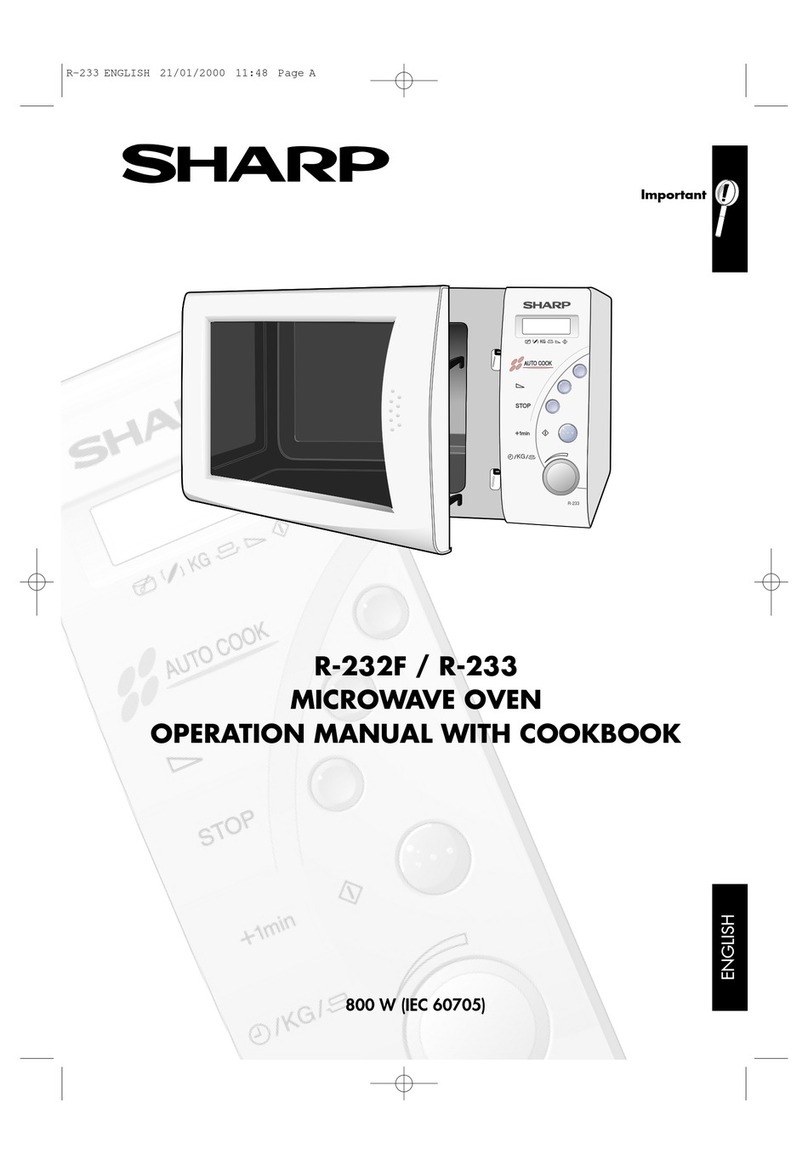
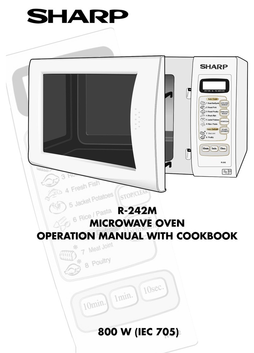
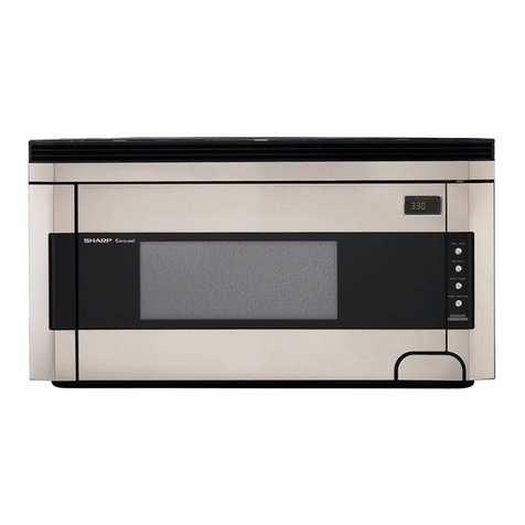
Sharp R-5H53 User manual

R-5H53
SHARP SERVICE MANUAL
s9111 R5H53J::
MICROWAVE OVEN
MODEL
in interests of user-safety the oven shcutd be restored :G .;s ,~rrg,r;d’
condition and oniy manufacturer orlginal svare qarrs -nus; x ~sec:
-‘i-c _
TABLE OF CONTENTS Fage
APPEARANCE VIEW ........................................................................................................... . . INSIDE COVER
GENERAL IMPORTANT INFORMATION .................................................................................. .... ..._.......... I
CAUTION, MICROWAVE RADIATION,WARNING ,,.......,.,..,..,,....,......,,.....,...,...,.,,....................,..,.,....,...... 1
PRODUCT SPECIFICATIONS ..................... ................................................................................................... 2
OPERATION SEQUENCE .............................................................................................................................. .. 3
FUNCTION OF IMPORTANT COMPONENTS ...................................................................................... ..,.... 4
SERVICING .........................*.............................................................................................................................. 5
TEST PROCEDURE ...........................................................................
TOUCH CONTROL ASSEMBLY .....................................................
COMPONENT REPLACEMENT AND ADJUSTMENT PROCEDl
MICROWAVE MEASUREMENT ......................................................
WIRING DIAGRAM ..........................................................................
PICTORIAL DIAGRAM .....................................................................
............................................................... 6
............................................................ 16
RE ..................................................... 23
............................................................ 27
............................................................ 28
............................................................ 29
CONTROL PANEL CIRCUIT ......................................................................................................................... 30
PRINTED WIRING DIAGRAM ..................................................................................................................... 31
PARTS LIST .................................................................................................................................................... 32
PACKING AND ACCESSORIES ................................................................................................................... 38
SHARP CORPORATION

R-5H53
APPEARANCE VIEW
1. Ventilation openings
2. Oven lamp
3. Oven door with see through
window
4. Coupling
5. Roller Stay
6. Removable turntable
7. Hinges
8. Safety door latches
9. Door open button
10. Touch Control Panel
1 1. Digital readout
12. Waveguide cover
13. Access cover for oven
lamp replacement
Touch Control Panel
SENSOR INSTANT ACTION 1 f
I -SENSOR !&ANT ACTlOb -
PADS J
Touch once to cook or reheat
4 popular menu.
iRESh ‘VEGETABLES II REHEAT ’
BEVERAGE 1 -NUMBER PADS
k
L
I /
!=
i-
/
&
r-
--
I
r=
t
/
1
I
1
1
/
I
1
/
I
I
/
-I
+-
C
r
t
SENSOR COOK PADS
Touch to select Fresh or
Frozen foods In Sensor modes. (
I
SENSOR COOK MENUS~-----l~
EASY DEFRQST PAD /i
Touch to defrost
entering weight.
MEMORY
Touch to enter one frequently
used cooking programme.
Touch to recall the memorized
programme. I
VARIABLE COOKING
CONTROL PADS
power setting.
If not touched, HIGH is auto-
matically selected.
STOP/CLEAR PAD -------l jL
Touch to erase during pro-
gramming.
Touch once to stop operation
of oven during cooking: touch
twice to cancel cooking pro-
gramme.
SENSCG C03K
’ Ross’ bee:
Z qoast lamb
cioast zh1cke.n
1 c
4 Lorned ;nea!
5 Desserts
0 Cake / Pudciric
7 Stewed iruc:
b Preserves iI I
9 Bacon
lC Porrlcge ii 6 1
11SOUP It
12 Casserole:
?3 Fish fillets j/ 7 i
1.4 Fice !I J
15 Pasta
16 Frozen o!nners
l? Pastrces js/
- MEMaRY I
*Place the roller stay on the
coupling in the oven and seat the
turntable on the roller stay.
I
i-
I
Touch to enter cooking times,
clock time, weight or quantrty
of food, or to select the Sensor
Cook menus.
-MORE( I\ 1,LESS{ v 1PADS
11
! 1
,
I
i j
I 1
I ;
i 1
Ji
IL ,
1
Touch to increase/decrease
the time in one minute incre-
ments during cooking or to
alter the doneness for the
Sensor Cook, Sensor instant
Action or Easy Defrost modes.
--INSTANT COOK/START PAD
Touch once to cook for 1
minute at HIGH or increase by
1 minute multiples each time
this pad is touched during
cooking.
Touch to start oven after
setting programmes.
r
AUTO START/CLOCK PAD
Touch to set clock or Auto
’ Start time.

ISI1 SltlVd
lAVkl!3VlCl E>NlkllM
hlElVV3SSV 13NVd
lOkIlN H3nOl
‘3Nl3lAki3S NOIPVkUklOzlNl LNVfl80dlNI lVkl3N3E)
NWdW ‘VHfSO
‘AOSZ uey1 a.JoLu
sa6ello~ le pasn aJe IS!\ s$Jed uo ,,+,, payJeu~ slJed aye 11~
3~aau~6ua aD!AJas pau!eJl
Aq A~uO Ino pa!JJe3 aq lsnw ~JOM J!edaJ pue 6~!3!/\Jas
.uaAo ayi ~I!M afjewep alq!s!A Jay10 he 30~ s! aJay (2)
*padJeM Jo paurJo~ap IOU s! loop ayl(a)
.pa6ewep IOU s! Gu!yDed Joop aql(3)
‘aA!Klajap $OU ale saSu!y pue slay3eJq JOOp aqJ_(g)
*pas013 41@1 s! JOOp ayl(v)
‘palnsua
ale slu!od Bu!Mo~]o~ aye lyun U~AO ayl alelad JOANN ,
,
E>NINt(VAA
neozcEakl~
-
-.iaua s! a3!Aap ayl al!~m euuaiue Jo apln6anem uado
ue o$u! yoo} JaAaN .pay3el$e peoi 6u!&Sqe A6Jaua
aAenlion!t.u e Inoyl!m ayr\ap ayr a]eJadO JaAaN ‘psJn3as
aq lsnw slayse6 pue sa6uelJ ‘sapin6aAeM ‘suo~i~auuo~
aAeMolD!Lu lndlno pue lndu! 11~ .paisauuo:, Jo pasn
AjJadcJdut! s! li 4; sa3iAap fju!lcJaua& aAeMoJD!u: Jay10
JO uo;lau6eur ayi UJGJ; ale!peJ AeL.u yZ!y~ A6Jaua aAeM
-OJS!LC!ayl 0: pasodxa aq IOU pinoqs sJaau!Bua a3!nJaS
NOElWKWLi 3AVMOkKHL/u
NOULnW3
‘r?SO.9F3t!
JapuaJ 01 pa!g!lenb aq II!N\ AaLg OS ‘lenueu; siq; 40 ixal aJilua
at.g Apn:s A/!njaJe:, sJaau!6ua a3iAJas Seyi papuawluo3aJ sl $1
‘3ogeuIJo4u; a3!nJas pue uolleJadg ci;l!l\n s;aau!6ua
a3!rtJas ‘dJo3 dneys ap!AoJd o; paJedaJd uaaq seq lenuelr\i s!ql
NOllV’tf3dO N3AO 3AVMOkl31lAl
NOIldlkl3S3Cl imaoud
lWflNb’iAl33lAM3S

R-5H53
PRODUCT DESCRIPTION
SPECIFICATIONS
ITEM
Power Requirements 240 Volts
50 Hertz
DESCRIPTION
Single phase, 3 wire earthed
-____
Power Consumption 1500w
__----- ---_ ___----
Power Output 750 watts nominal of RF microwave energy (2 litre water load)
850 watts (IEC-705 1988)
Operating frequency of 2450M Hz
_---
Case Dimensions Width 616 mm
Height 366 mm
Depth 477 mm
Cooking Cavity Dimensions
--____
Control Complement
Width 406 mm
, Height 248 mm
Depth 422 mm
’ Touch Control System
Clock( I:00 - 12:59 )
Timer (0 - 99 min. 99 sec. )
Microwave Power for Variable Cooking
Repetition Rate;
HIGH ................................ Full power throughout the cooking time
MED HIGH ............................................... approx. 70% of Full Power
MED .......................................................... approx. 50% of Full Power
MED LOW (DEFROST) .......................... approx. 30% of Full Power
LOW .......................................................... approx. 10% of Full Power
SENSOR COOK (Fresh 1 -- ‘I 5, Frozen 11 -- 17)
INSTANT COOKSTART
AUTO START
MEMORY
Se! Weig n:
SENSOR INSTANT ACTION
EASY DEFROST
MORE/LESS pads
Approx. 23 kg
NOTE: Numbers and letters shown after sentences such as “RD44101 U” are for factory use only.
2

R-5H53
OPERATION SEQUENCE
ription of component functions
The fo llowing is a desc
during oven operation.
OFF CONDITION
(RD7:“O:U;
Closing the oven door activates all the door interlock
switches: upper latch switch and lower latch switch.
(In this condition, the monitor switch contacts are
opened.) The stop switch is activated by the latch
head. When oven is plugged In, 240 volts A.C. IS
supplied to the control unit. But no components in ine
oven will operate. (Figure O-l on page 28)
1. The display will show flashing “88:88”,
2. To set any program or set the clock, you must touch
the STOP/CLEAR pad first.
3. The dispiay WIII clear and ” ” appears in :he d;.-;-
play and the time counts up every minute:.
NOTE:When the door is opened by pushrng the door
open button, the contacts of :he reiav RY -1 sre
closed, ther! rhe oven kmp lights.
MICROWAVE COOKING CONDlTfON
HIGH COOKING
Program desired coctk~ng trme and Variaole Cook+ng
Control by touching ?he NUMBER pads and the HiGti
pad of the Variabi e Cooking Cont:ol. When rhe STP?,T
pad is touched, the foiiowing operations occur:
1. The contacts of reiays closed and components
connected to the relays are turned on as foilovds.
(Figure O-2 on page 28’1
~__. I---
Relay cOcnt?C:ed ccmoGnet77is
__~_ .-._.- --_-- _~-- __ _________
RY-1 Oven lamp,Turncable rrotor Fan motor
RY-2 Power Transformer -______--
2. 240 volts A.C. is supplied to the primary winding
of the power transformer. The voltage is converted
to about 3.3 volts AC. output on the filament
winding and approximately 2000 volts A.C. high
voltage on the secondary winding.
3. The 3.3 volts filament winding voltage heats the
magnetron filament and the 2000 volts high voltage
is sent to the voltage-doubling circuit, where it is
doubled to a negative voltage of approximately
4000 volts D.C.
4. The 2450 MHz microwave energy produced in the
magnetron generates a wave length of 12.24 cm.
This energy is channeled through the waveguide
(transport channel) into the oven cavity, where the
food is placed to be cooked.
5. Upon completion of the cooking time, the power
transformer, oven lamp, etc. are turned off, and the
generation of microwave energy is stopped. The
oven will revert to the OFF condition.
6. When the oven door is opened during a cooking
cycle, the monitor switch. upper and lower latch
switches are activated with the followrng resuits.
The crrcuits to the turntable motor, fan motor and
high voltage components are deenergized, the oven
lamp remains on, and the digital readout displays
the time still remaining in the cook cycle when the
door was opened.
7 The monitor switch IS electrrcally monrtoring the
operation of the upper and !ower latch switches and
6 mec5ts nrcally associated with the door so that !t
jNi!i funGion tn the foilowtng sequence.
(1 ) ‘v?ihen the door is opened from a closed posi-
Thor;. the upper larch and lower latch switches
operate to open their contacts first, and then
Ihe sontacts of the monrtor swatch ciosed and
the :contacts of the stop switch open.
t21 Wheq the door IS closed from the open position,
:ne comacts oi rhe moG:iIor switch should be
craned firs: and rhe ,zontac;s of :he stop swatch
ar;> ziosec and ther tipcer !atch and lower
;atc,les are ZiGsee,
/T’
* -?cs sf 1,113ap~?r ap‘-j ;c;Q-~>~:;aTcjy
di LV 5wttch switches
;a’: wit’r: -:p,eir {be “,o~~tac:s l;i:>~e~:i i,\!ken -,he doOr -
!2
pr.C;n!AA
vyv* i”.A, Tr;e ccjcn:::zr S\$/iiCh \.A/;ii form s short c:rc;:i;
Thro!-:cjh ‘h? :‘i!$+ and ihe ‘-!pLy?r _31?c ‘cJ\n/ef ja:ch ftise
s*jk ctc:?es i:du~;f-~ :pe fus5 tfj brr~~,y
MED HIGH, MED; MED LOW (DEFROST), LOW
COOKING
When :iarrabie Cooking- Power 1sprogrammed, the 240
voits A.C. is supplied to the power transformer
rntermittent!y through the contacts of relay! RY -2)
which is operared by the control unrt within a 32 sec-
ond time base. Microwave power operation IS as fol-
iO\NS:
_.____
VARI-MODE ON TIME OFF TIME
-__.
HIGH 32 sec. 0 sec.
(100% power) -__
MED HIGH 24 sec. 8 sec.
(approx. 70% power)
MED 18 sec. 14 sec.
(approx. 50% power)
MED LOW (DEFROST) 12 sec. 20 sec.
(approx. 30% power)
LOW 6 sec. 26 sec.
(approx. 10% power)
Note: The ON/OFF time ratio does not correspond
with the percentage of microwave power, be-
cause approx. 2 seconds are needed for heating
of the magnetron filament. (RD71401 U)
3
R-5H53
FUNCTION OF IMPORTANT COMPONENTS
DOOR OPEN MECHANISM
The door can be opened by pushing the open button
on the control panel, refer to Figure D-l. When the
open button is pushed, the open plate on the open
device pushes in the door lever on the door, operating
the latch head linkage. The lower and upper latch
heads are moved upward, and released from the lower
and upper latch hodks. Now, the door can be opened.
(RD72GOl U;
\ UPPER
LATCH
LOWER HEAD
LATCH
HEAO
DOOR
OPEN
BUT-TON
Figure D-l. Door f)pen Mechanism
UPPER AND LOVVER LATCH SWITCHES
The lower latch switch IS mounted in the lower latch
hook and the uppe! latch switch is mounted in the
uoper latch hook. They are activated by the latch
heads on the door. When the door is opened, their
switches interrupt the circuit to all components except
the oven lamp and touch contra! panel. A cook cycle
can not take piace until the door is firmly closed there
by activating both interlock switches.
MONITOR SWITCH
The monitor switch is activated (the contacts opened)
by the upper latch head on the door while the door is
closed. This switch is intended to render the oven in-
operative by means of blowing the fuse when the
contacts of the upper latch switch and the lower latch
switch fail to open when the door is opened.
Function
1. When the door is opened, the monitor switch con-
tacts close (to the ON condition) due to their being
normally closed. At this time the upper latch switch
and the lower latch switch are in the OFF condition
(contacts open) due to their being normally open
contact switches.
2. As the door goes to a closed position, the monitor
switch contacts are opened first and then the con-
tacts of upper and lower latch switches close. (On
opening the door, each of these switches operate
\
tnverselv.)
3. If the door is opened and the contacts of the upper
latch switch and lower latch switch fail to open, the
fuse blows simultaneously with closing of the
monitor switch contacts.
CAUTION: BEFORE REPLACING A BLOWN FUSE,
TEST UPPER LATCH SWITCH, LOWER
LATCH SWITCH, MONITOR SWITCH
AND MONITOR RESISTOR FOR
PROPER OPERATION. (REFER TO
CHAPTER “TEST PROCEDURE”).
Figure D-Z Latch Switches and Monitor Switch
MAGNETRON TEMP. FUSE
The temperature fuse located on the cavity top plate
near the magnetron to prevent damage to the
magnetron if an overheated condition develops in the
tube due to cooling fan failure, obstructed air ducts,
dirty or blocked air intake, etc.
Under normal operation, the temperature fuse remains
closed. However, when abnormally high temperatures
are reached within the magnetron the temperature fuse
will open at 115’C, causing the oven to shut down.
This is a fuse and it does not reset.
OVEN THERMAL CUT-OUT (‘RD72403U)
The thermal cut-out located on the wall of the steam
duct. It is designed to prevent damage to the oven
cavity, if foods in the oven catch fire due to over heat-
ing produced by improper setting of cooking time or
failure of control unit etc..
Under normal operation, the oven thermal cut-out re-
mains closed. However, when abnormally high tem-
peratures are reached within the steam duct, the oven
thermal cut-out will open at 115OC, causing the oven
to shut down. (‘RD72407U)

R-5H53
SERVICING
WARNING TO SERVICE PERSONNEL
Microwave ovens contain circuitry capable of producing very high voltage ;;nd current, contac:
lowing parts: yjj;n ;oi -
High voltage capacitor, Power transformer, Magnetron, High voltage re ctifler assembly, High vo;;age 7a~ness.
REMEMBER TO CHECK JiJ
1) Disconnect the supply.
2) Door opened, and wedged open.
3) Discharge high voltage capacitor
’ WARNING AGAINST THE CHARGE OF THE
HIGH-VOLTAGE CAPACITOR
The high-voltage capacitor remains ,zharged
about 60 seconds after the oven has been
switched off. Wait for 60 seconds and then
short-circuit the connection of the
high-voltage capacitor (that is, of the con-
necting lead of the hrgh-voltage rectifier:
against the chassis with the use of an insu-
lated screwdriver.
Sharp recommend that wherever possibie
fault-finding is carried out wirh the suppiy discon-
nected. It may in, some cases, be necessary to
connect the supply after the outer case has been
removed, in this event carry out 30 checks and then
disconnect the leads to the primary of the power
transformer. Ensure that these leads remain isolated
from other components and the oven chassis. (Use
insulation tape if necessary.) When the testing is
completed carry out 3[3, checks and reconnect the
leads to the primary of the power transformer.
REMEMBER TO CHECK B
11 Reconnect all teads removeo fro,m car-
:,D(2:-2:?;c
_-
during testing.
2) Replace the ourer case i,catsl!nel;
3) Reconnect the suppiy
a?; Run the oven Checic ail ftii;ct:cr;s
Microwave ovens should not be ru:; ?rn~:\. T~l -0s~
for the presence of m;Zrovvave 3nerf~v JV::-~~:”s
3
cavltjf, p/aca a czg of CsiC; :~a:?-‘-’ ‘2 r , ‘?~e 3~ ?r~
‘,urc:table, close the dt>or acl:! set Fe ;~s~:~:e~.b,~~+t~
timer for two (2) lmjc:L;les. ~53: r,ble ,qc:-j5r 12~1 -;
HiGH and pusi? the ST;;=- z~:tfi=
.iui. 'l',jr‘t! r’?t Ti,‘i;2
.q:qutes has $iapsed ,‘;j,~e: 3? 7~r5 ~:a:?mii~~ I~-?.::.
.A% -v
rha; the water 2snew 70: !f :h* :,v&er ;erya;rs 2-i~
carry 0~1 3C checks 3cd s-,3,y~~ire :?,E -:-
nections to the corn~o~e:-: 5eifig xstss!
When all service work is completed, and the oven is fully assembled, the microwave power output should
be checked and a microwave leakage test carried out.
(RD81GO1H)
TROUBLESHOOTING GUIDE
When troubleshooting the microwave oven, it is helpful
to follow the Sequence of Operation in performing the
checks. Many of the possible causes of trouble will
require that a specific test be performed. These tests
are given a procedure letter which will be found in the
“Test Procedure”section.
IMPORTANT: If the oven becomes inoperative be-
cause of a blown fuse in the
monitor-upper latch-lower latch switch
circut, check the monitor switch, upper
and lower latch witches and monitor
resistor before reolacina the fuse.

R-5H53
TEST PROCEDURE
POSSIBLE
CASE AND
~;X'~~TIVE
ONDITION PROBLEM
)FF
:ONDITION
N
ONDITION
ENSOR
30KING
3NDITION
Home fuse blows when power supply cord i:
plugged into wall receptacle.
FUSE M8A blows when power supply cord is
plugged into wall receptacle. (The door is closed]
“88:88” does not appear in display but powel
supply cord is plugged into wall receptacle.
Display does not operate properly wher
STOP/CLEAR pad is touched. (An audible signa
should sound and time of day should appear or
display.
Display appears, but oven lamp does not light
with door open.
When the door is opened, fuse M8A blows,
Fan motor does not operate.
(Display appears)
Turntable motor assembly does not operate
(Display appears)
Oven lamp does not light.
(Display appears)
Home fuse or breaker operates when the IN-
STANT COOK/START pad is touched.
oven seems to be operating but little
or no heat is produced in oven load. (Microwave
cooking control is set at FULL POWER position.)
Oven does not cook properly when programmed
for variable cooking powers. (Oven operates
properly at FULL POWER)
Oven goes into cook cycle but shuts down before
end of cooking cycle.
Oven stop as soon as when the INSTANT
COOK/START pad is touched.
Oven does not cook properly when programmed
in the EASY DEFROST cooking mode. (Oven op-
srates properly by manual cooking mode.)
&en is in the sensor cooking condition or one
iouch reheat cooking condition, but AH sensor
does not end 1st stage or does not stop cooking
cycle or the oven stops soon.
-
I
:,
-
i
-
;
!i
:
i
s
:
M
E
-
-
-
-
-
-
-
--
4
-
-
T
d
-
-
F
-
!z
$
e
E
2
S
i
t
-
-
r,
-
H
ir
:
i
I
H
-
-
I
>
-
T
-
F
;
R
ii
E
z
II
ki
-
?
5
1
d
-
?
E
Gi
E
ii
:
H
S
F
:
H
-
-
-
-
-
-
-
-
-
-
-
-
-
-
-
i
!
i
1
I
I
(
(
\
/
1
E
-
$
kz
2
s
z
-
3
3
-
-
-
-
z
-
ET
F
E
$
::
E
E
:
-
3
-
-
1
-
T
-
ii
E
i?
L
:
a'
Y
-
I
d
-
-
i
-
z
i
ii
;
i
a
ii
-
-
V
-
-
-
0
-
::
S
E
E
R
Ei
S
ii
!
-
-
-
1
;i-i
-
z
ii
ii
E
E
:
B
-
-
3
-
-
6

R-5H53
RE = Replace / CK = Check
;-;
-
:
!i
s
‘L’
E
L
Y
17
4
E
c
-
?
d
-
u
-.
V
-
-
-
-
-
i;;
-
t
iFi
L
A
M
P
A
N
3
;
k
F
-
Q
V
-
,--x
4
-
-
-
ii
-
S
i-i
0
F
E
y
+\
;
H
.A
R
N
z
:
-
,-
u
-
e
L
I
u
-
--
r?
4
--
-
n
d
-
-
3
-
ZK
-
z
z
E
D
w
i
H
i:
x
E
s
s
-
?
c/
-
-
n
LA
-
3
5
-
hi
A
i
0
Y
iJ
5
-
7.
V
-
-
-
-
5
-
:
-?I
E
F
TJ
s
E
0
2
;
$
‘.-
I<
E
3
-
-
E
-
‘W
;
s
0
;
i:
T
-r
s
-
-
.
__
3
-
3
-
cx
-
M
&
A
D
J
g
s
:
ti
$
7.
Ii
-
q
d
A
u
-1
V
m
w
-
r?
L
-
w
--
-
4
-
-
-
-
-
-
-
-
-
-
-
__
-
-
-
-
-
-
-
-
-
-
-
-
-
7

R-5H53
TEST PROCEDURES
PROCEDURE
LETTER COMPONENT TEST
MAGNETRON TEST
NEVER TOUCH ANY PART IN THE CIRCUIT WITH YOUR HAND OR AN INSULATED ’
TOOL WHILE THE OVEN IS IN OPERATION. I
CARRY OUT 3D CHECKS
Isoiate the magnetron from the high voltage circuit by removing all leads connected to the filament
terminal.
To test for an open circuit filament use an ohmmeter to make a continuity test between the
magnetron filament terminals, the meter should show a reading of less than 1 ohm.
To test for a short circuit filament to anode condition, connect ohmmeter between one of the fil-
ament terminals and the case of the magnetron (ground). This test should be indicated an infinite
resistance. If a low or zero resistance reading is obtained then the magnetron should be replaced
MICROWAVE OUTPUT POWER (2 liter water load) (RD82AOl Uj
The following test procedure should be carried out with the microwave oven in a fully assembled
conditron (with outer case fitted). Microwave output power from the magnetron can be measured
by way of substitution, i.e. it can be measured by using a water load how much it can be absorbed
by the water load. To measure the microwave output power in the microwave oven, the relation
of calorie and watt is used.
calorie is generated. When P(W) heating works for t(second), approximately P x t/4.2
On the other hand, if the temperature of the water with V(ml) rises AT
(‘C) dunng this microwave heating period, the calorie of the water is V x AT.
-
The formula is as follows;
P x t /’4.2 = V x AT P (W) = 4.2 x V x CIT : t
:Cld:rcondition for the water load !s as follows:
Room temperature ....... .............around 20°C
Water load ......2300 mi Initial temperature Power supply Voltage .............Rated voltage ;
... .. IO+1 ‘C
P = 75 x CT Heating time ...... 1min. 52 sec. ~
I
Vieeasurin~ method:
Li,‘iUse two i iitre Pyrex beakers with a diameter of approximately of 72cms.
51 Place i iitre of 1O’C water in each beaker.
C> Mark Tl on the one beaker and mark T2 on the other one. And stir the water and measure the
temperature of water the thermometer and note them. The graduation of the thermometer must
be scaled by 0.1 “C at minimum and an accurate mercury thermometer is recommended.
Dj Piace th t
e wo beakers as touching each other in the centre of the cavity.
E) Set the timer to f minute and 52 seconds at 100% power (the time required to raise the water
temperature 70 degrees C.)
FI The time must be measured with stopwatch or wristwatch.
G) After 1 minute and 52 seconds, stop the oven by opening the door.
H) Remove the two beakers from the oven and measure the temperature of the water by stiring the
water with the thermometer and noting the readings.
Example
Initial temperature ...............................................................................
Temperature after 1min. 52 set Tl =lO”C T2=11”C
. ........................................................
Temperature difference Cold-Warm Tl = 20°C T2 = 21 “C
= =
Mean temperature rise AT ........................................... ATI 10°C AT2 10°C
........
Measured output power AT = (AT1 +AT2) / 2 = (IO’C + 10°C) / 2 = 10°C
The equation is “P= 75 x AT”
--- .................................*................. P= 75 x 10°C = 750 Watts
NOTE: The measured output power should be at least +I5 % of the rated output 1
power.
CAUTION: 1°C CORRESPONDS TO 75 WATTS.
REPEAT MEASUREMENT IF THE POWER IS INSUFFICIENT.
8

R-5H53
TEST PROCEDURES (CONT’D)
PROCEDURE
LETTER COMPONENT TEST
I q-1OC) iT2 OC! i-r: OCi o-2 “Cl
Hea: up for I mm. 52 set
MICROWAVE OUTPUT POWER (lEC-705-1988)
The following test procedure should 5e carried out with :he mtc:ob~,ave oven in a fuiiy assembled
condition (outer case fitred j I Microwave output power from the magnetron can be measured by
way of IEC 705. i.e. it can be measured by using waIer load how +m:~chI: car: be absorbed by the
water load. To measure the microwave output power !r! the microwave ov?g, the reiatton of [;a;-
orie and watt is used. When PtW! heating works for t(second), ar=erox,ma:eiv
is generated. On :he other hand P x t, 4 18: calorie
If :he temperature oi Ihe water JV!T~4::~:i‘; VISESAT ; C: durlnc:
this microwave heating per:od, the Calorie *z~frhe wager is ‘V x AT
The formula is as follows:
Pxt a,?87 = L, x 2-T p p/) = 4 18: ,y ‘,I .‘( ‘\T :
Our condition for the water ioad is as foiiows:
Room temperaturF .I.. ,.. ... arouna 20-G
Waler load ........ SO0 g ?o\,j/er SCCClt ‘joitage
P = 85 x AT Iriit!ai tempera:l;re ..... .I 0 12-C Heat:ng Lime
~- --- --~--.-- ~~- --~ --
Rated *image
49 set
Measuring condition:
1. Container
The water container must be a cylindrrcal borosilicate glass vessel naving a maxrmum mater!ai
thickness of 3 mm and an outside diameter of approximately 190 mm.
2. Temperature of the oven and vessel
The oven and the empty vessel are at ambient temperature prior to the start of the test.
3. Temperature of the water
The initial temperature of the water is (10 f 2)X.
4. Select the initial and final water temperature so that the maximum difference between the final
water temperature and the ambient temperature is 5°C.
5. Select stirring devices and measuring instruments in order to minimize addition or removal of
heat.
6. The graduation of the thermometer must be scaied by 0.1 ‘C at minimum and an accurate
thermometer.
7. The water load must be (1000 + 5) g.
8. “t” is measured while the microwave generator is operating at full power, Magnetron filament
heat-up time is not included.
NOTE: The operation time of the microwave oven is “t + 2” sec. 2 sec. is magnetron filament
heat-up time.
Measuring method:
1. Measure the initiai temperature of the water before the water is added to the vessel
(Example: The initial temperature Tl = 11 “C)
2. Add the 7 litre water to the vessel.
3. Place the load on the centre of the shelf.
4. Operate the microwave oven at HIGH for the temperature of the water rises by a value n T of
(10 &- 2)“C.
5. Stir the water to equalize temperature throughout the vessel.
6. Measure the final water temperature. (Example: The final temperature T2 = 21 “C)
7. Calculate the microwave power output p in watts from above formula.
Initial temperature __.-___--
.............................
........................................................................ Tl = 11°C
9

R-5H53
TEST PROCEDURES (CONT’D)
PROCEDURE
LETTER COMPONENT TEST
Temperature after (49 + 2) = 51 sec. .................................................................... T2 = 21 “C
Temperature difference Cold-Warm .,.................................................,..........,..... ATI = 10°C
Measured output power
The equation is “P= 85 x AT” ................................................... P= 85 x 10°C = 850 Watts
-_____ -___
JUDGMENT: The measured output power should be at least +I5 % of the rated
output power.
CAUTION: 1°C CORRESPONDS TO 85 WATTS. REPEAT MEASUREMENT IF THE POWER IS
INSUFFICIENT.
T2”C
*eal up for 51 sec.
(RD82A03U)
B POWER TRANSFORMER TEST
WARNING: High voltages and large currents are present at the secondary winding
and filament winding of the power transformer. It is very dangerous to
work near this part when the oven is on. NEVER make any voltage
measurements of the high-voltage circuits, including the magnetron
filament.
:ZkFFk’ 3:-lT 32 CHECKS,
Disconnect the leads to the primary winding of the power transformer. Disconnect the filament
and secondary winding connections from the rest of the HV circuitry. Using an ohmmeter, set
on a low range, it is possible to check the continurty of al! three windings. The following readings
shouid be obtained :-
a. Primary wrnding ----------less than 7.5 ohms.
5. Secondary winding -------80 ohms.
c. Filament wending ---------less than 2 ohm.
If the reading obtained are not as stated above, then the power transformer is probably faulty and
should be replaced.
CARRY OUT 4J CHECKS (RD82405J1
c HIGH VOLTAGE RECTIFIER ASSEMBLY TEST
HIGH VOLTAGE RECTIFIER TEST
CARRY OUT 3D CHECKS.
isolate the high voltage rectifier assembly from the HV circuit. The high voltage rectifier can be
tested using an ohmmeter set to its highest range. Connect the ohmmeter across the terminal
B-CC of the high voltage rectifier and note the reading obtained. Reverse the meter leads and note
IO

R-5H53
TEST PROCEDURES (CONT’D)
PROCEDURE
LETTER COMPONENT TEST
this second reading. The normal resistance is infinite in one direction and more than 100 k!2 In
the other direction.
CARRY OUT 4R CHECKS
ASYMMETRIC RECTIFIER TEST
CARRY OUT 3D CHECKS. *qzL ‘JOLTAGE
REcT,F,ER
Isolate the high voltage rectifier assembly from the HV circuit. The asymmetric rectifier can be
tested using an ohmmeter set to its highest range. Connect the ohmmeter zc:oss the :ermlnals
ATB of the asymmetric rectifier and note the reading obtained. Reverse the meter leads and note
this second reading. If an open circuit is indicated in both directions then the as:/mme:ric rectifier
is good. If an asymmetric rectifier is shorted in either direction, then the :he asymme:r:c ecrliier
is probably faultly and must be replaced with the high voltage rectifier. When the asvmmwic
rectifier is defective, check whether magnetron, high voltage rectifier, high voltage sabreor
ment winding of the power transformer is shorted. fila-
CARRY OUT 4R CHECKS
NOTE: FOR MEASUREMENT OF THE RESISTANCE OF THE RECTIFiE?, T?E !3&3-E?tzS
OF THE MEASURING INSTRUI\/IENT MUST HA,‘V/E,A ‘Jc-JLTAGE AT LEAST E i’C~y.5
BECAUSE OTHERWISE AN iNFINITE RESISTANCE MIGHT BE SHC’\/VN iiN BGik
DIRECTIONS. G’-x-“---
4rOL3’d.‘,
D HIGH VOLTAGE CAPACITOR TEST
CARRY OUT 30 CHECKS.
A.
B.
C.
D.
E.
F.
G.
Isolate the high voltage capacitor from the circuit.
Continuity check must be carried out with measuring instrument which is set io the highesT
resistance range.
A normal capacitor shows continuity for a short time (kick) and then a resisiance of about
10 MR after it has been charged.
A short-circuited capacitor shows continuity all the time.
An open capacitor constantly shows a resistance about 10 MQ because of its internal 10
MQ resistance.
When the internal wire is opened in the high voltage capacitor, the capacitor shows an in-
finite resistance
The resistance across all the terminals and the chassis must be infinite when the capacitor
is normal.
If incorrect readings are obtained, the high voltage capacitor must be replaced.
CARRY OUT $J CHECKS (RD82604J)
E SWITCH TEST
CARRY OUT D CHECKS.
Isolate the switch to be tested and using an ohmmeter check between the terminals as described
in the following table. Table: Terminal Connection of Switch
Plunger Operation COM to NO COM to NC COM; Common terminal
Released Open circuit Short circuit NO; Normally open terminal
Depressed Short circuit Open circuit NC;
1 Normally closed terminal
If incorrect readings are obtained, make the necessary switch adjustment or replace the switch.
CARRY OUT $J CHECKS.
11

R-5H53
TEST PROCEDURES (CONT’D)
PROCEDURE
LETTER COMPONENT TEST
F MONITOR SWITCH TEST
CARRY OUT 3D CHECKS.
Before performing this test, make sure that the upper latch switch lower latch switch are oper-
ating properly referring to the above Switch Test Procedure. Disconnect the wire leads from the
monttor switch (NC) terminal. Check the monitor switch operation by using the ohmmeter as
follows. . BLACK WIRE
When the door is open the meter
should indicate a closed circuit. When
the monitor switch actuator is pushed
by a screw driver through the lower
latch hole on the front plate of the
oven cavity with the door opened (in
this condition the plunger of the
monitor switch is pushed in), the me-
ter should indicate an open circuit. If
Improper operation is indicated, re-
place the defective switch. After test-
ing the monitor switch, re-connect the
wrre lead to the monitor switch (NC)
terminal.
CARRY OUT 4R CHECKS
G ~~~~
TEMPERATURE FUSE TEST
CARRY OUT 30 CHECKS
A continuity check across the temperalure fuse termrnals should Indicate a closed circuit unless
the temperature of the temp. fuse reaches approxrmatelv “r‘I 5’ C. An open the temperature fuse
indicates overheating of the magnetron assembfv. If the temperature fuse indicates a open err-
cuit, replace the temperature fuse and check for restricted air flow to the magnetron through the
opening In the chassis, especrally the air duci ant: fan motor.
CARRY OUT &R CHECKS
THERMAL CUT-OUT TEST
CARRY OUT 3D CHECKS
A continuity check across the thermal cut-out terminals sould indicate a closed circuit. If the
temperature of the steam duct reaches approximately 115°C the thermal cut-out opens. (This
thermal cut-out reset at below -2O’C) An open thermal cut-out indicates overheating of the oven
cavity. Check for restricted air flow to the magnetron through the opening in the chassis, espe-
cially the air duct and fan motor.
CARRY OUT Q CHECKS
CAUTION IF THE THERMAL CUT-OUT INDICATES OPEN CIRCUIT, REPLACE THE THER-
MAL CUT-OUT.
I BLOWN FUSE F M8A
CARRY OUT a CHECKS
1. If the fuse M8A is blown, there could be shorts or ground in electrical parts or wire har-
ness. Check them and replace the defective parts or repair the wire harness.
2. If the fuse M8A is blown, there could be short in the asymmetric rectifier or there could
be a ground in wire harness. A short in the asymmetric rectifier may have occured due to
short or ground in H.V. rectifier, magnetron, power transformer or H.V. wire. Check them
and replace the defective parts or repair the wire harness.
3. If the fuse M8A is blown when the door is opened, check the upper latch switch, lower
latch switch monitor switch and monitor resistor.
12

R-5H53
TEST PROCEDURES (CONT’D)
PROCEDURE
LETTER COMPONENT TEST
If the fuse M8A is blown by incorrect door switching replace the defective switch(s) and
the fuse M8A.
CARRY OUT 4R CHECKS
CAUTION: Only replace fuse M8A with the correct value replacement.
J MONITOR RESISTOR TEST
CARRY OUT 30 CHECKS.
Disconnect the leads from the monitor resistor.
Using an ohmmeter and set on a low range.
Check between the terminals of the monitor resistor. The resrstance of monitor is aporox. 0.8Q.
If incorrect readings are obtained, replace the monitor resistor and check the fuse ~Vl8A. upper
latch switch, lower iatch swatch and wire harness.
CARRY OUT @ CHECKS.
TOUCH CONTROL PANEL ASSEMBLY TEST
The touch control panel consists of circurts including semiconductors such as LSI ICs, etc
Therefore, unlike conventional microwave ovens, proper maintenance cannot be performec \mitl?
only a voltmeter and ohmmeter.
vided into two units, Control In this service manual, the touch control panel assembly IS do-
Unit and Key Unit, and troubleshooting by unit replacement is de-
scribed according to the symptoms indicated.
1. Key Unrt.
The foiiowing symptoms indrcate a defective key unrt. Replace the kev unit.
a) When touching the pads, a certain pad produces no signal at ail.
b) When touching a number pad. two figures or more are displayed.
c> When touching the pads, sometimes a pad produces no signal
2. Control Panel
The following symptoms indicate a defective control unit. Replace the controi unit.
2-l tn connection with pads.
a) When touching the pads, a certain group of pads do not produce a signal.
b) When touching the pads, no pads produce a signal,
2-2 In connection with indicators
a) At a certain digit, all or some segments do not light up.
b) At a certain digit, brightness is low.
c) Only one indicator does not light.
d) The corresponding segments of all digits do not light up; or they continue to light up.
e) Wrong figure appears.
f) A certain group of indicators do not light up.
g) The figure of all digits flicker.
2-3 Other possible problems caused by defective control unit.
a) Buzzer does not sound or continues to sound.
b) Clock does not operate properly.
c) Cooking is not possible.
d) Proper temperature measurement is not obtained.
L EASY DEFROST TEST
(1) Place one cup of water in the center of the turntable tray in the oven cavity.
(2) Close the door, touch the “EASY DEFROST” pad.
(3) Touch the number 5 pad to enter weight (0.5 Kg. is set).
(4) Touch “START” pad. Now the oven is in EASY DEFROST cooking condition.
(5) The oven will operate as follows.
1ST STAGE 2ND STAGE
LEVEL TIME LEVEL TIME
100?6 75sec. 50% 125sec.
3RD STAGE
LEVEL TIME
0% 400sec.
4TH STAGE
LEVEL TIME
30% 160sec.
13

R-5H53
TEST PROCEDURES (CONT’D)
PROCEDURE
LETTER COMPONENT TEST
(6) If improper operation is indicated, the control unit is probably defective and should be
checked.
M RELAY TEST
Remove the outer case and check voltage between Pin Nos. 1 and 3 of the 3-pin connector (A)
on the control unit with an A.C. voltmeter. The meter should indicate 240 volts, if not check oven
circuit.
RYI and RYZ Relay Test
These relays are operated by D.C. voltage.
Check voltage at the relay coil with a D.C. voltmeter during the microwave cooking operation.
DC. voltage indicated ..........Defective relay.
DC. voltage not indicated ........Check diode which is connected to the relay coil. If diode is
good, control unit is defective.
I RELAY SYMBOL OPERATIONAL CONNECTED COMPONENTS
VO LTAG E I
RYI Approx. 13 V.D.C.
RY2 ADDrox 14V. D C.
Oven lamp/Turntabie motor/Cooling fan motor
Power transformer
N PROCEDURES TO BE TAKEN WHEN THE FOIL PATTERN ON THE PRINTED WIRING
BOARD (PWB) IS OPEN. .
To protect the electronic circuits, this model is provided with a fine foil pattern added to the
primary on the PWB, this foil pattern acts as a fuse. If the foil pattern is open, follow the trou-
bieshooting guide given below for repair.
Problem. POWER ON, indicator does not light up.
__--____ ---__
ZTEPC
Lj i . OCC!JRRENCE CAL’SE OR CORRECTION ---__
7 ‘TL - -____
I I!e rated vo!tage IS no: apolled to POWER terminal Check supply voltage and oven main unit
si CPU connector (CN-A) ____--___- _
-, Theratedvoltage IS spoiled to pr!mar\ srde of power Power transformer or secondary cIrcuIt defective.
transfcrmer Check and repair ~--____
3nli ;latterr a; “a’ IS broken ‘inser: lumper wire Jl and solder.
Pa:reri- a: ’ 2” apd “0” are broker *insert the coil RCILF2003YAZZ between “c” and
“d”
hJC3T[ L 4+ tpe rime of tpese repairs make a vlsua! IP-
spect’on of the varlstor fol burning damage
and examine the transformer with tester for the
presence of [aver shor?-clrcult (check primary
coil resisrance)
It anv abnormal conaittoT? IS detected, replace
the defective parts.
0 AH SENSOR TEST
Checking the initial sensor cooking condition
(1 ) The oven should be plugged in at least five minutes before sensor cooking.
(2) Room temperature should not exceed 95”F(35”C).
(3) The unit should not be installed in any area where heat and steam are generated. The unit
should not be installed, for example, next to a conventional surface unit. Refer to the
“INSTALLATION Instructions”.
(4) Exhaust vents are provided on the back of the unit for proper cooling and air flow in the
cavity.To permit adequate ventilation, be sure to install so as not to block these vents.
There should be some space for air circulation.
14

R-5H53
TEST PROCEDURES (CONT’D)
PROCEDURE
LETTER COMPONENT TEST
(5) Be sure the exterior of the cooking container and the interior of the oven are dry. Wipe off
any moisture with a dry cloth or paper towel.
(6) The Sensor works with food at normal storage temperature.For example, chicken pieces
would be at refrigerator temperature and canned soup at room temperature.
(7) Avoid using aerosol sprays or cleaning solvents near the oven while using Sensor settings.
The sensor will detect the vapor given of by the spray and turn off before food is properly
cooked.
(8) After about 41 minutes if the sensor has not detected the vapor of the food, ERROR will
appear and the oven will shut off.
Water load cooking test
Make sure the oven has been plugged in at least five minutes before checking sensor cook op-
eration. The cabinet should be installed and screws tightened.
(1) Fill approximately 200 milliliters (7.2 oz) of tap water in a 1000 milliliter measuring cup.
(2) Place the container on the center of tray in the oven cavity.
(3) Close the door.
(4) Touch SENSOR COOK FRESH pad and number pad 8. Now, the oven is in the sensor
cooking condition and SC-8 will appear in the display.
(5) Touch Start pad.The oven will operate for the first 16 seconds, without generating micro-
wave energy.
NOTE: ERROR will appear if the door is opend or STOP/CLEAR pad is touched during first stage
of sensor cooking.
(6) After approximately 16 seconds, microwave energy is produced, oven should turn off when
water is boiling (bubling).
If the oven does not turn off, replace the AH sensor or check the control unit, refer to explanation
below:
TESTING METHOD FOR AH SENSOR AND/OR CONTROL UNIT
To determine if the sensor is defective, the simplest method is to replace it with a new replacement
sensor.
(1) Disconnect oven from power supply and remove outer case.
(2) Discharge the high voltage capacitor.
(3) Remove the AH sensor.
(4) Install the new AH sensor.
(5) Re-install the outer case.
(6) Reconnect the oven to the power supply and check the sensor cook operation proceed as
follows:
6-l. Fill approximately 200 milliliters (7.2 oz) of tap water in a 1000 milliliter measuring
cup.
6-2. Place the container on the center of tray in the oven cavity.
6-3. Close the door.
6-4. Touch SENSOR COOK FRESH pad and number 8 pad.
6-5. Touch Start pad. The control panel is in automatic Sensor operation.
6-6. The oven will turn off automatically when the water is boiling (bubbling).
If new sensor dose not operate properly, the problem is with the control unit.
CHECKING CONTROL UNIT
(1) Disconnect oven from power supply and remove outer case.
(2) Discharge the high voltage capacitor.
(3) Disconnect the wire leads from the cook relay.
(4) Disconnect the sensor connector that is mounted to lower portion of control panel.
(5) Then connect the dummy resistor circuit (see fig.) to the sensor connector of control panel.
(6) Reconnect the oven to the power supply and check the sensor cook operation proceed as
follows:
6-1. Touch SENSOR COOK FRESH pad and number 8 pad.
6-2. The control panel is in the sensor cooking operation.
6-3. After approximately 20 seconds, push plunger of select switch.
This condition is same as judgement by AH sensor.
6-4. After approximately 3 seconds, cooking operation turns off, an audible signal will
sound, and the display will then revert to the time of day.
15

R-5H53
TEST PROCEDURES (CONT’D)
PROCEDURE
LETTER COMPONENT TEST
If the above is not the case, the control unit is probably defective.
If the above is proper, the AH sensor is probably defective. PLUNGER
I
To Connector (FI
on Control Unit
Rl,R2 : 22R &- 1% 1i2W
R3:lOkQ + 5% 1/4W
R4 : 1MCI f 5% 1/4W
NC
NO
F-l - m
F-Z- rc
Sensor Dummy Resistor Circuit
OUTLINE OF TOUCH CONTROL PANEL
ihe touch control section consists of the foliowing
units as shown rn the touch control panei circuit.
iI> Key Unit
(2) Contra! Unit
Tne prrnctpal functions of these units and the signals
communrcated among them are explained beiow.
Key Unit
The ke\f unii is com2osec of a matrix. signals generated
:r: the iSI are sent T#- ; e
P63,P04,P36,PG7, p: 7 P: fBnrP< Jey unit thrnugh
LYnen a key pat !s roscned, a signal is c.ompieted
through :ne kev dni: and passed oack to the LSi
:aroUgh zs-;-?Iz 12 i>erf5:7- the funcirc>T :r,a: n/as ye-
ouesied.
Control Unit
Zontroi iintt cons:sis .of iSi. power source circuit,
synchronizrng signal crrcurt. ACL circuit, buzzer circurt,
temperature measurement clrcu;:, reheat sensor cfrcuit
and Indicator circuit.
‘I) LSI
This LSI controls tne temperature measurement
signai. reheat sensor signal. key strobe signal. relay
driving signai for oven function and indicator sig-
nal.
2) Power Source Circuit
This circuit generates
contra! unit. voltage necessary in the
Symbol Voltage Application
-----
VC -5.ov
VP LSI (ICI), ACL circuit
-26V Fluorescent display tube : Grid
VF- 3Vac and anode voltage
Filament of fluorescent display
VF+
---- tube
(VF- to VF-C voltage)
3)
4)
5)
fi)
71
8)
9)
Synchronizing Signal Circuit
The power source synchronizing signal is avaiiable
in order to compose a basic ‘standard time in the
clock circuit.
It accompanies a very smali error because it works
on commercral frequency.
ACL Circuit
A. circuit to generate a signal which resets the LSI
to ;he inltiai state when power is supplred.
&uzzer Circuit
The buzzer responds to signais from the LSI to
emrt noticing sounds (key touch sound and com-
aletion sound). (RD9; AA1U/
Reheat Sensor Circuit
This ctrcuit detects moisture of a food which is
cooking,to allow its automatic cooking.
Stop Switch
A switch to “tell” the LS! if the door is open or
closed.
Relay Circuit
To drive the magnetron, fan motor. turntable motor
and light the oven lamp.
Indicator Circuit
indicator element is a Fluorescent Display.
Basically, a Fluorescent Display is a triode having
a cathode, a grid and an anode. Usually, the cath-
ode of a Fluorescent Display is directly heated and
the filament serves as cathode.
The Fluorescent Display has 6-digits, 13-segments
are used for displaying figures.
16

R-5H53
LSl(lZA393DR)
DESCRIPTION OF LSI
The I/O signals of the LSl(lZA393DR) are detailed in the following table.
PIN NO. 1 L
SIGNAL VREF I l/O IN
Reference voltage input terminal.
A reference voltage appiied to the A/D converter In the LSI. Connected to GND (OV) RD(:Ij<Aji
PIN NO. 2-4
-__- 1 SIGNAL IN7-IN5 I I/O IN
Heating constant compensation terminal. +?),G>.-ji:_it
PIN NO 5
-____-- -.--__- ~--__---~~ -~
_i SIGNAL INA
__- --~- - ----~~~ ~~_.~~ I ~
It 0 /IN
Terminal to change functions according to the model.
Signal in accordance with the model in operation is applied to se? up its function i-‘
_,-A-2 1
_~>-- ._/
PIN NO. 6 SIGNAL i rd3 i 0 IN
Input signal which communicates the door open!‘close information to LSI.
Door closed; “H” level signal! OV). / Door opened: “L” level signal(-5V) - ---
,.L-’ ^L;‘j
PIN NO. 7 -~._~.r7YzILS’“!!!~L~ - ‘f“” ~~ - I i cz 129 ~--
Connected to GND.
PIN NO. 8 .---L. SIGNAL \r\jl I- i ,P
I 2 jp.;
AH sensor input. This input is an anaiog input ierm;nai iron -.he AH sc?nsor sirc,~,:, 3flG ;~Fc~c:& +: y--q 1 3
y
converter built into the LSI. ‘i’,..,c1-
t-u__r~-
PIN NO. 9
~___ ~~.__7z!G!!lpIN0 .~ ~~_- ~_ -T=-- IN
Used for initial balancing of the bridge circuit(absoiu:e humidity sensor): This input !s an anal05 *!~i=,-: rermlnai
from the AH sensor circuit, and connected to the A D converter burit into the LS;
PIN NO. IO-14 1 SIGNAL P47-P43
~__-- __.- -~-~-_.-------~-~ L i/O OUT
-~ _ ~~
Used for initial balancing of the bridge circuit(absolute humidity sensor)
PIN NO. 15-l 7
~_____.
Terminal not used. SIGNAL P42- P40 110 OUT
__- I
PIN NO. 18 1 SIGNAL P37 1 l/O OUT
---____
Oven lamp driving siqnal.
To turn on and off shut-off relay( RYI ). I 20 muc
r
The square waveform voltage is delivered to the ‘- - - - -+
relay( RYl ) driving circuit and relay (RY2) control circuit. L-L
PIN NO. / 19 1 SIGNAL P36 I I/O OUT
Terminal not used.
PIN NO.; 20 1 SIGNAL P35
Maclnetron high-voltage circuit driving signal.
To turn on and off the cook relay(RY2).
l/O OUT
I --
In high operation, the signals holds “L” level during H’GH ?TT____
microwave cooking and “H” level while not cooking, In
other cooking modes (MED HIGH, MED, MED LOW,
LOW) the signal turns to “H” level and “L” level in repe-
MED“l”qLm
tition according to the power level. ME0
17

R-5H53
PIN NO. / 35 1 SIGNAL R2 I I/O / IN
Siqnal similar to R3.
When any one of G-10 line keys on key matrix is touched, a corresponding signal will be input into R2. (RD93CA8U)
PIN NO. 36 1 SIGNAL Rl I I/O I IN
Signal similar to R3.
When any one of G-9 line keys on key matrix is touched, a corresponding signal will be input into RI. (RD93CABU)
PIN NO. 37 RO
1 SIGNAL I I/O IN
-~-____~
Siqnal similar to R3.
When any one of G-8 line keys on key matrix is touched, a corresponding signal will be input into RO. (RD93CABUi
PIN NO. 38
__- ______ ~___ VP
~~ 1 SiGNAL I l/O IN
Anode (seqment) of Fiuorescent Display light-up voltaqe: -26V.
Vp voltage of power source circuit input. (RD93GABlJI
PIN NO. 39-40
Terminal not used. L SiGNAL P17-PI6 -_lL!!!LOUT!
PIN NO. 41 SIGNAL PI 5
-__ ___-
Seqment data siqnais.
The relationship between signals and indicators are as foilows:
I I/O OUT
_____-
Signal Segment
Pl 5 ............................ ..i. .. ....LB
PI 4... ...................... ...............UB
P13... ............... ...... .......~.... .. k
P12 ..,........................ ..........‘. .. j
PII. .... ......*..............~...I.........L,, I
,
PI0 ............ .......................... .I. h
PO7..................... ..................... g
Signai
PC6 . . . ... , . Segment
s..........,. f
PO5 .... ........... ......................
PO4 ............... ................... :
PO3 ., ............ ......................... c
PO2 ...t........... ~./.,....................... b
PO? ................. ........................ a
moq 1-i
JxrKI:z.-2w.
PIN NO. 42 1 SIGNAL PI4 I I/O OUT
Seqment data siqnil.
Signal similar to PI 5. Key strobe siqnai.
Signal applied to touch-key section. A pulse signal is input to RO-R3 terminal
while one of G-l line keys on key matrix is touched. (RD939A3U1
PIN NO. i 43 1 SIGNAL PI3 I I/O / OUT
Seqment data siqnal. Signal similar to PI 5. (RD939AZUl
PIN NO. / 44
Segment data signal.
Signal similar to PI 5.
PIN NO. ; 45
Seqment data signal.
Signal similar to PI 5.
SIGNAL 1 PI2 I l/O j OUT
Kev strobe siqnal.
Signal applied to touch-key section. A pulse signal is input to RO-R3 terminal
while one of G-2 line keys on key matrix is touched. (RD939A3U)
SIGNAL PI 1 I l/O / OUT
Kev strobe siqnal.
Signal applied to touch-key section. A pulse signal is input to RO-R3 terminal
while one of G-3 line keys on kev matrix is touched. (RD939A3U)
PIN NO. / 46 1 SIGNAL PI0 l/O / OUT
Seament data siqnal. Signal similar to PI 5. I
PIN NO. / 47 1 SIGNAL PO7
Seqment data siqnal. Kev strobe siqnal.
(RD939AZU)
I I/O I OUT
Signal similar to PI 5. Signal applied to touch-key section. A pulse signal is input to RO-R3 terminal
while one of G-4 line keys on key matrix is touched. (RD939A3U)
19
Other Sharp Microwave Oven manuals

Sharp
Sharp R-580D Use and care manual

Sharp
Sharp R-820BK User manual

Sharp
Sharp Carousel R-7A85 Use and care manual

Sharp
Sharp R-94ST User manual

Sharp
Sharp R260 User manual

Sharp
Sharp R-334 User manual

Sharp
Sharp R-852N Instruction Manual

Sharp
Sharp R-21JVF User manual

Sharp
Sharp R-8730-A User manual

Sharp
Sharp R-238A Instruction Manual

Sharp
Sharp R842SLM User manual

Sharp
Sharp Carousel R-312AK User manual

Sharp
Sharp R-426HS User manual

Sharp
Sharp R-671 Instruction Manual

Sharp
Sharp Microwave Drawer User manual

Sharp
Sharp R-798-A Instruction manual

Sharp
Sharp R-667R User manual

Sharp
Sharp R-33STM Instruction Manual

Sharp
Sharp Carousel R-231ZS Use and care manual

Sharp
Sharp R-810ES User manual