Sharp R-8470 User manual

SHARP SERVICE MANUAL
S9610R8470Jll
COUNTER TOP
CONVECTION
MICROWAVE OVEN
Photo R-8470 In the interests of user-safety the set should be restored to its original
condition and only parts identical to those specified should be used.
TABLE OF CONTENTS Page
FOREWORD ....................................................................................................................................................... 1
CAUTION, MICROWAVE RADIATION .......................................................................................................... 1
PRODUCT DESCRIPTION ............................................................................................................................... 2
OPERATION INSTRUCTIONS ......................................................................................................................... 3
OPERATION .................................................................................... .I................................................................. 4
SERVICING ..................................................................................................................................................... 10
TOUCH CONTORL PANEL ASSEMBLY ..................................................................................................... 20
COMPORNENT REPLACEMENT AND ADJUSTMENT PROCEDURE ................................................... 29
MICROWAVE MEASUREMENT PROCEDURE .......................................................................................... 34
PACKING AND ACCESSORIES ................................................................................................................... 35
PICTORIAL DIAGRAM .................................................................................................................................. 36
CONTROL PANEL CIRCUIT (R-8470) ....................................................................................................... 37
CONTROL PANEL CIRCUIT (R-8570) ....................................................................................................... 39
PRINTED WIRING BOARD .......................................................................................................................... 41
PARTS LIST .................................................................................................................................................... 42
SERVICE INFORMATION FOR CONTROL UNIT ...................................................................................... 47
SHARPCORPORATION

I--
R-8470
R-8570
(R-8470)
(R-8570)

R-8470
R-8570
SERVICE
MANUAL
SHARP
COUNTER
TOP
/
CONVECTION
MICROWAVE
OVEN
R-8470/
R-8570
FOREWORD
/
This Manual has been prepared to provide Sharp Corp. Service
Personnel with complete Operation and Service Information for
the SHARP CONVECTION MICROWAVE ovens, R-8470/
1
R-8570.
1
It is recommended that service personnel carefully study
the
entire text of this manual so they will be qualified to render
satisfactory customer service.
Check interlock switches and door seal carefully. Special at-
tention should be given to avoid electrical shock and microwave
radiation hazard.
CAUTION
MICROWAVE RADIATION
Personnel should not be exposed to the microwave energy
which may radiate from the magnetron or other microwave
generating devices if it is improperly used or connected. All
input and output microwave connections, waveguides,flanges
and gaskets must be secured. Never operate the device without
a nicrowave energy absorbing load attached. Never look into
an open waveguide or antenna while the device is energized.
SHARPCORPORATION
OSAKA, JAPAN
$4
”
PRODUCT
DESCRIPTION
%a%
*
,
^
k:
OPERATING
INSTRUCTIONS
~
*;:
fg”:
*.a
&$&a’$*
i
r
,
OPERATION
I
SERVICING
4:‘:
c%~
si
TOUCH
CONTROL
COMPONENT
REPLACEMENT
AND
ADJUSTMENT
MICROWAVE
MEASUREMENT
*
PARTS
LIST

R-8470
R-8570
PRODUCTION DESCRIPTION
EXPLANATION OF MICROWAVE COOKING AND CONVECTION COOKING
The Sharp Convection-Microwave Oven uses micro- cules are changing direction every half cycle or oscil-
wave energy and the sheath heater to produce heat in lating back and forth 4,900,000,000 times per second.
the food to be cooked. This high speed oscillation causes friction between the
Unlike conventional ovens microwave energy will cook
foods without applying external heat. molecules, thereby converting the microwave energy
to heat.
Microwaves, which are short electromagnetic waves
of RF (radio frequency) energy, pass through materials
guch as glass, paper, china and most plastics. Materi-
als such as metal and aluminum foil tend to reflect
microwaves and may be used only as recommended in
the cooking instructions. Materials with a high
moisture content, like most foods, will absorb micro-
wave energy. As the microwave energy at a frequeny
of 2450 Megahertzenters the food, the molecules align
themselves with the energy. Because the microwave
are changing polarity every half cycle, the food mole-
However, cooking by microwave energy only,
produces no browning or searing (unless cooking a
roast of sufficient thickness). This microwave oven is,
therefore, equipped with a sheath heater to provide
browning of the food.
The combination of the heater plus high-speed circu-
lation of air by a circulating fan around the food pro-
vides fast cooking and browning of foods
conventionally with or without the addition of micro-
wave energy.
SPECIFICATION
ITEM
Power Requirements
Power Output
Convection Power Output
Case Dimensions
Cooking Cavity Dimensions
Control Complement
Set Weight
DESCRIPTION
240 Volts
6 Amperes (Microwave)
6.7 Amperes (Convection)
50 Hertz
Single phase, 3 wire earthed
700 watts normal of RF microwave energy (2 liter water lod)
Operating frequency of 2450MHz
1500 Watts
Width 627 mm
Height 408 mm including foot
Depth 505 mm
Width 395 mm
Height 256 mm
Depth 422 mm
Micrwave Power for Variable Cooking
Repetition Rate;
HIGH ............................... Full power throughout the cooking time
MED.HIGH ............................................ approx. 70% of Full Power
MEDIUM ............................................... approx. 50% of Full Power
MED.LOW(DEFROST) ........................ approx. 30% of Full Power
LOW ....................................................... approx. 10% of Full Power
Convection Temperature Control Range;
40 to 250 “C
Auto Start Cooking
Comp Defrost Cooking
Convection Cooking
Instant Cooking
Sensor Cooking (R-8570 only)
Compu Cooking (R-8570 only)
Approx. 34 kg

R-8470
R -8570
OPERATING INSTRUCTIONS
R-8470
R-8470
3-m
@ INDICATORS
@I COMPU DEFROST SYMBOL
@ CONVECTION FAN SYMBOL
Touch to select Compu Defrost setting.
INSTANT COOKTM PAD
Touch to cook for 1 minute at HIGH or in-
crease bv 1 minute multioles durina variable
Il/~h cooking.
NUMBER AND TEMPERATURE PAD
Touch to enter cookina times. clock time or
convection temperature.
CONVECTION COOKING FUNCTION PADS
Touch to cook for each function.
VARIABLE COOKING CONTROL PADS
Touch to select microwave power setting If
not touched, HIGH is automatically selected.
TIMER/HOLD PAD
Touch to set minute timer or HOLD
the setting.
AUTO START/CLOCK PAD
Touch to set clock or auto start time
STOP/CLEAR PAD
Touch to erase during programming.
Touch once to stop operation of oven
during cooking; touch twice to cancel
FT@-+= “MEL PEtart oven.
R-8570
pucO~~~~~~~~ FAN SYMBOL
n
1 ” CONVECTION FAN SYMBOL
I
IQY+ @@/g/tg&i-
MIX MID “16” Wli ID
CON”MEDLow RAM MO
AUTOstm mm. aimi cm -
COMPU DEFROSTTM SYMBOL
This symbol flashes and varies in size whenever the compu defrost
power IS on.
LIGHTED DIGITAL DISPLAY
Shows readout of cooking time. cooking instruction or time of day.
INDICATORS
.- CONYECTlON
, not _
--A _~~
LOWMIX
-T-.-L ye
-,7 -\
IYGH
AS, SL35,
-ym GRlli \
+==-A-
.- SLOWCOOK 5 mot
A- ow lyiiz
~-. --
&MEDLOW’I
E of/ml ~
__= Medaare 17* ~
=
E .1’:, 8 22x t
,Lki!--
l
Te;E;,i.:9-i
-.---.,
y-\
~0W.::s”.I,
025592
iMEP1ATSTAR,
I HOLD,CLOCK/
+
CONVECTION COOKING FUNCTION PADS
Touch to cook with each function.
SENSOR COOK PAD
Touch to select Sensor Cook settings.
COMPU COoKTM PAD
Touch to select CompuCook settings.
INSTANT COOK PAD
Touch to cook for 1 minute at HIGH or Increase by 1 minute multi-
ples during variable cooking.
COMPU DEFROSTTM PAD
Touch to select CompuDefrost settings.
NUMBER AND TEMPERATURE PADS
Touch to enter cooking times, clock time or convection tem-
perature.
VARIABLE COOKING CONTROL/FOOD DONENESS SETTING PADS
Touch to select mIcrowave power setting. If not touched, HIGH IS
automatlcallv selected.
Touch to select food doneness setting for CompuCook.
If not touched, Med Done IS automatlcallv selected.
TIMER/HOLD PAD
Touch to set the minute timer or hold (pause) the cooklng cycle
during a multlple sequence programme.
AUTO START/CLOCK PAD
Touch to set clock or auto start time.
START PAD
Touch to start oven.
STOP/CLEAR PAD
Touch to erase during programnxng.
Touch once to stop operanon of oven during cooking; touch twice
to cancel cooking program.
3

OPERATION
DESCRIPTION OF OPERATING SEQUENCE
I
!!
h
1
I
!/
i
I
I
The
following is a description of component functions
during oven operation.
OFF CONDITION
Closing the door activates both door interlock
switches: upper latch switch and lower latch switch.
(In this condition, the monitor switch contacts are
opened
.)
The
stop switch is activated (contacts closed) by the
latch head, when the door is closed.
When oven is plugged in, the 240 volts A.C. is supplied
to the relay unit. (Figure O-l).
I,
The
display will show flashing
“88:88”.
To set any program or set the clock, you must first
touch the STOP/CLEAR (or STOP/CANCEL) pad.
The display will clear, and
I:00
will appear and
count up every minute.
Note: When the door is opened, the oven lamp comes
on.
2. A signal is input to the control unit, energizing the
coil of shut-off relay (RY6).
RY6 contacts close, completing a circuit to the
damper motor.
The damper motor now operates moving the damper
to the open position, thereby closing the contacts
of the damper switch inputs a signal to the control
unit.
The coil of relay RY6 is de-energized, opening its
contacts, thereby turning off the damper motor.
COOKING CONDITION
HIGH
COOKING
Program desired cooking time and Variable Cooking
Control by touching the NUMBER pads and the HIGH
pad of the Variable Cooking Control. When the COOK
(or START) pad is touched, the following operations
occur:
1. The contacts of relays are closed and components
connected to the relays are turned on as follows.
(For details, refer to Figure O-2)
RELAY CONNECTED COMPONENTS
RY-1 power transformer
RY-2 oven lamp/turntable motor
RY-3 convection motor
Fly-4
heating element
RY-5 fan motor
RY-6 damper motor
2. The 240 volts A.C. is supplied to the primary wind-
ing of the power transformer and is converted
to
about 3 volts A.C. output on the filament winding,
and approximately 2200 volts A.C. on the high
voltage winding.
3. The filament winding voltage heats the magnetron
filament and the H.V. winding voltage is sent to a
voltage doubler circuit.
4. The microwave energy produced by the magnetron
is channeled through the waveguide into the cavity
feed-box, and then into the cavity where the food
is placed to be cooked.
5.
6.
Upon completion of the cooking time, the power
transformer, oven lamp, etc. are turned off, and the
generation of microwave energy is stopped. The
oven will revert to the OFF condition.
When the door is opened during a cook cycle,
monitor switch, stop switch, upper latch switch are
activated with the following results. The circuits to
the turntable motor, the cooling fan motor, and the
high voltage components are deenergized, the oven
lamp remains on, and the digital readout displays
the time still remaining in the cook cycle when the
door was opened.
7.
The monitor switch is electrically monitoring the
operation of the upper latch switch and is mechan-
ically associated with the door so that it will func-
tion in the following sequence.
(1) When the door opens from a closed position,
the upper latch switch opens their contacts,
and then the monitor switch contacts close.
(2) When the door is closed from the open posi-
tion, the monitor switch contacts first open,
and then the contacts of the upper latch switch
close.
If the upper latch switch failes with their contacts
closed when the door is opened, the closing of the
monitor switch contacts will form a short circuit
through the monitor fuse, upper latch switch , causing
the monitor fuse to blow.
MED.HIGH,
MEDIUM,
MED.LOW(DEFROST),
LOW
COOKING
When the Variable Cooking is programed, the 240 A.C.
voltage is supplied to the power transformer
intermittently through the contacts of the relay which
is operated by the control unit within a 32 second time
base. The microwave power operation is as follows:
VARI-MODEON TIME OFF TIME
HIGH 32 sec. 0 sec.
(approx. 100% power)
MED.HIGH
24 sec. 8 sec.
(approx. 70% power)
MEDIUM18 sec. 14 sec.
(approx. 50% power)
MED.LOW( DEFROST) 12 sec. 20 sec.
(approx. 30% power)
LOW6 sec. 26 sec.
(approx. 10% power)
Note: The ON/OFF time ratio does not correspond
with the percentage of microwave power, be-
cause approx. 2 seconds are needed for heating
of the magnetron filament.
CONVECTION COOKING CONDITION
PREHEATING
CONDITION
Program desired convection temperature by touching
the CONVECTION pad and the temp. pad.
When the START pad is touched, the following oper-
ations occur:
4

R
-8470
R-8570
1.
2.
3
The coil of shut-off relays (RY2, RY3 and RY5) are
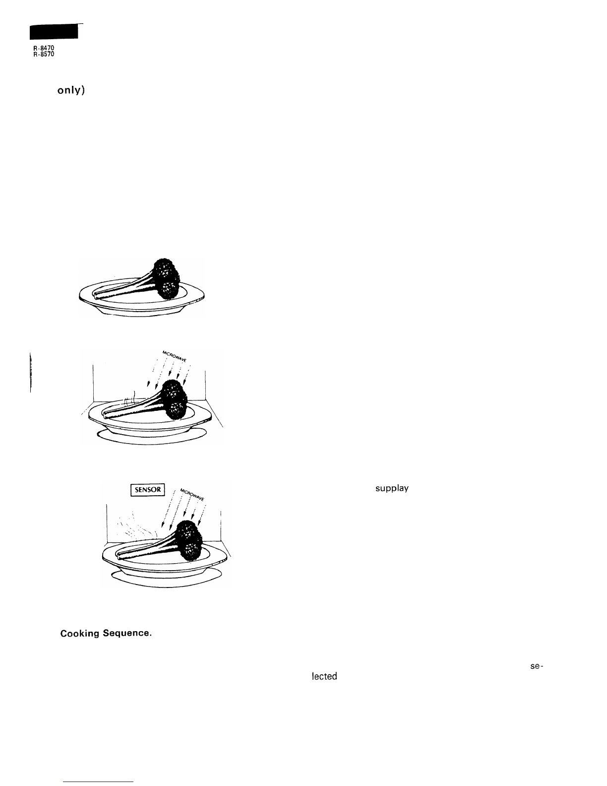
energized, the oven lamp, cooking fan motor,
turntable motor and convection motor are turned
on.
The coil of relay (RY6) is energized by the control
unit. The damper is moved to the closed position,
opening the damper switch contacts.
The opening of the damper switch contacts sends
a signal to the LSI on the control unit
de-energizing the relay (RY6) and opening the
circuit to the damper motor.
The coil of heater relay (RY4) is energized by the
control unit and the mains supply voltage is added
to the heating element.
When the oven temperature reaches the selected
preheat temperature, the following operations oc-
cur:
4-1.
4-2.
The heater relay is de-energized by the con-
trol unit temperature circuit and thermistor,
opening the circuit to the heating element.
The oven will continue to function for
15
minutes, turning the heater on and off, as
needed to maintain the selected preheat
temperature.
The oven will shut-down completely after
15 minutes.
CONVECTION
COOKING
CONDITION
When the preheat temperature is reached, a beep signal
will sound indicating that the holding temperature has
been reached in the oven cavity. Open the door and
place the food to be cooked in the oven.
Program desired cooking time and convection temper-
ature by touching the NUMBER pad, CONVECTION
pad and Temperature pad.
When the START pad is touched, the following oper-
ations occur:
I.
2.
3.
4.
5.
The numbers of the digital readout start the count
down to zero.
The oven lamps, turntable motor, cooking fan mo-
tor and convection motor are energized.
Heater relay (RY4) is energized (if the cavity tem-
perature is lower than the selected temperature)
and the mains supply voltage is added to the
heating element to return to the selected cooking
temperature.
Upon completion of the cooking time, the audible
signal will sound, and oven lamps, turntable motor,
cooking fan motor and convection motor are
de-energized. At the
end.of
the convection cycle,
if the cavity air temperature is above 120
OC,
the
circuit to RY5 will be maintained (by the thermistor
circuit) to continue operation of the cooling fan
motor until the temperature drops below 100
OC,
at which time the relay will be de-energized, turn-
ing off the fan motor. Relay RY3 will however,
open as soon sa the convection cycle has ended,
turning off the convection fan motor. This will now
cool and allow the damper door to open.
At the end of the convection cook cycle, shut-off
relay (RY6) is energized turning on the damper
motor. The damper is returned to the open position,
closing the damper switch contacts which send a
signal to the control unit, de-energizing shut-off
relay (RY6).
AUTOMATIC MIX COOKING CONDITION
Program desired cooking time and temperature by
touching the number pads and the LOW MIX/BAKE
or HIGH MIX/ROAST pad
When the START pad is touched, the following oper-
ations occur:
1.
2.
3.
4.
5.
6.
The numbers of the digital readout start the count
down to zero.
The shut-off relay (RY2, RY3 and RY5) are
ener-
gized, turning on the oven lamps, turntable motor,
and cooling fan motor.
The shut-off relay (RY6) is energized.
The damper door is closed from the open position.
The heater relay (RY4) is energized, adding the
mains supply voltage to the heating element.
Now, the oven is in the convection cooking con-
dition.
When the oven temperature reaches the selected
temperature, the following operations occur:
6-l. The power supply voltages is added to the
heating element and power transformer al-
ternately.
6-2. The heating element operates through the
heater relay (RY4) contacts and the power
transformer operates through the cook relay
(RYI
)
contacts.
6-3. These are operated by the control unit to
supply alternately within a 32 second time
base, convection heat and microwave en-
ergy.
The relationship between the convection and micro-
wave power operations are as follows.
Note: The ON and OFF time ratio does not correspond
with the percentage of microwave power, be-
cause approx. 2 seconds are needed for heating
of the magnetron filament.
MICROWAVE
POWER
(MICR0.l
-
Appmx.
10%
II
II,
‘ON
I
I
CONVECTION
TEMPERATURE
OFF
-
184vc
LOWMIX’
BAKE
lCONVEC.1
I
32
UC.
I
I-
I
HIGH MIX
--
ROAST
MICROWAVE
FOWER
-
A~ox.
30%
CONVECTION
TEMPERATURE
=
2oo”c
Note: During alternate Microwave/Convection opera-
tion, the convection heater is energized only if
the cavity temperature drops below the set tem-
perature.
5

R-8470
R-8570
SENSOR COOKING CONDITION (R-8570
only)
Using the SENSOR COOK function, the foods are
cooked without figuring time, power level or quantity.
When the oven senses enough steam from the food, it
relays the information to its microprocessor which will
calculate the remaining cooking time and power level
needed for best results.
When the food is cooked, water vapor is developed.
The sensor “senses” the vapor and its resistance in-
creases gradually. When the resistance reaches the
value set according to the menu, supplementary cook-
ing is started.
The time of supplementary cooking is determined by
experiment with each food category and inputted into
the LSI.
An example of how sensor works:
1. Broccoli at room temperature.
Vapor is emitted very slowly.
2. Heat broccoli. Moisture ‘and humidity is emitted
rapidly. You can smell the aroma as it cooks.
3. Sensor detects moisture and humidity and calcu-
lates cooking time and variable power.
Cooking Sequence.
1. Touch SENSOR COOK pad.
NOTE:The oven should not be operated on SEN-
SOR COOK immediately after plugging in
the unit. Wait five minutes before cooking
on SENSOR COOK.
2. Select desired Sensor setting.
3. Touch START pad.
The coil of shut-off relay (RY-1) is energized, the
oven light and cooling fan motor are turned on, but
the power transformer is not turned on.
4. After about 16 seconds, the cook relay (RY-2) is
energized. The power transformer is turned on,
microwave energy is produced and first stage is
started.
The 16 seconds is the cooling time required to re-
move any vapor from the oven cavity and sensor.
NOTE: During this first stage, do not open the door
or touch STOP/CLEAR pad.
5.
When the sensor detects the vapor emitted from the
food, the display switches over to the remaining
cooking time and the timer counts down to zero.
At this time, the door may be opened to stir food,
turn it or season, etc.
6. When the timer reaches zero, an audible signal
sounds. The shut-offrelay and cook relay are
de-energized and the power transformer, oven
light, etc. are turned off.
7. Opening the door or touching the STOP/CLEAR
pad, the time of day will reappear on the display
and the oven will revert to an OFF condition.
COMPUCOOK (R-8570 only)
COMPUCOOK will automatically compute the oven
temperature, microwave power and cooking time for
baking, roasting and broiling.
Set the
desired
program bytouching
the
COMPUCOOK pad, and number pad.
Enter the weight by touching the Number pads
When the START pad is touched, the following oper-
ations occur:
1.
2.
The COOK indicator will light and the Convection
Fan Symbol will rot ate.
The cooking time will appear on the display and
start counting down to zero.
The cooking time is adjusted automatically ac-
cording to the setting quantity or weight of food.
The shut-off relays (RY2, RY3, RY4 and RY5) are
energized, turning on the oven lamp, turntable
motor, cooling fan motor and convection motor.
The power supplay voltage is added to the heating
element.
Now, the oven is in the convection cooking mode.
When the oven temperature has reached the pro-
grammed convection temperature, the oven goes
into the programmed cooking mode.
At the end of the COMPUCOOK cycle, the damper
is returned to the open position and the oven will
be off condition.
The cooling fan will remain on until the oven has
cooled.
3.
4.
5.
6.
COMPU DEFROST COOKING
The COMPU DEFROST key is a special function key
to defrost meats and poultry faster and better.
COMPU DEFROST 1 to 5 automatically defrosts roast
beef, etc.
Each key has 3 defrost stages.
When the desired COMPU DEFROST number is
lected
and the food weight is entered by using
number pad’s, the oven will cook according to
special cooking sequence.
se-
the
the

R-8470
R-8570
1,::
I
25
g
5
YE
N
1
1
p
0
2
m
1
’
:
z
b-q
c-d
‘r
1
:
‘;
1%
Y
zIF, 0
5
g
5’
.:I
E
4
J
2
;(
:
0
2
t
5
02
2
z
FZ$$
F
0
I
;
s;ggsg:
5
oOU>OEUa
$?
OZ3)vl3Cf
000~0l-
OUI-Oi-v,
p
-N
C-3
P
r-IF--E
’
\
4j
ZI
,i
0
‘T
z211
i
:
(Il[
/
z
L-p&
2
5
oooo
*
$i:O$
I=
Q
$E;$-z
so”
,“o~pq$
G?
Wok-3
gyzyp
Z
-:
5
5
y=>
-Z$gpP
otwvJt=z
.o
$2X:
~Lu,-JQ
5
oLL
QaOL
-u4ak
w
OOCCYU-+a
I
Lip
:ggz:
OVL>Uv,
”
z
-N
0
s
5
a
1
L
s
cu
+
0
5
4
2
-a
0
Y
iy
25
=
m
-_-
8
k
z
g:i
2::
---++%
-.-
6
;
5:
IC
Via
*C
0
.-
+
0
5
E
0
’
:
2
:e
a
G
ao
r
iiF
.-
Eye
66
vi
6
?
7
m
.-
IA
0
cc
00
c
‘J
.F’G
=E
‘0
%I
-g
.E
EY
4
50
v)L.
0
Eg
&Yi
hi
6
2!
3
m
.-
IA
E
.-
w
.-
z
s
t=
0
I
0
.-
c,
E
z
ci
E
6
.
6
E
$
.-
L
7

R-8470
R
-8570
DESCRIPTION AND FUNCTION OF COMPONENTS
UPPER
AND
LOWER LATCH
SWITCHES
The upper and lower latch switches are activated by
the latch heads on the door. When the door is opened,
the switches interrupt the circuit to the power trans-
former, etc. For detais, refer to Oven Schematic dia-
gram.
And the switches interrupt the circuit to the heating
element for model which is provided the heating ele-
ment.
A cook cycle cannot take place until the door is firmly
closed thereby activating both latch switches.
Fi
/+
k
’
UPPER
LATCH
normally closed. At this time the upper latch switch
are in the OFF condition (contacts open) due to
their being normally open contacts switches.
2. As the door goes to a closed position, the monitor
switch contacts are first opened and then the upper
latch switch contacts close. (When opening the
door, each of these switches operate inversely.).
3. In the door is opened and the upper latch switch
contacts fail to open, the fuse blows simultaneously
with the closing of the monitor switch contacts.
CAUTION: BEFORE REPLACING A BLOWN FUSE,
TEST THE MONITOR SWITCH, UPPER
LATCH SWITCH FOR PROPER OPERA-
TION. (REFER TO CHAPTER “TEST PRO-
CEDURE”)
DOOR OPEN
MECHANISM
The door can be opened by grasping the door handle
and pulling strong.
When the door is pulled, the lower and upper latch
heads mounted in the door are raised up to release
them from the latch hooks.
The door can now be opened.
LATCH
SWITCH
.
Latch,Monitor
and
stop Switch
MONITOR SWITCH
The monitor switch is activated (the contacts opened)
by the upper latch head on the door while the door is
closed. This switch is intended to render the oven in-
operative by means of blowing the fuse when the
contacts of the upper latch switch falles to open when
the door is opened.
Functions:
1. When the door is opened, the monitor switch con-
tacts close (to ON condition) due to their being
Go
t
-
UPQER
LATCH
LOWER
LATCH
HEAD
HEAD
Figure
D-2.
Door
Open
Mechanism

R
-8470
R-8570
DAMPER
OPEN-CLOSE
MECHINISM
Usually, the damper is open position except during the
convection cooking.
Damper position is set automatically by damper motor,
damper switch, motor cam and damper shaft.
These components are operated according to the signal
that judges the microwave cooking or convection
cooking operation in the control unit.
Microwave Cooking:
Damper is in the open position, because a portion of
cooking air is channeled through the cavity to remove
steam and vapors given off from the heating foods.
It is then exhausted at the top of the oven cavity into
a condensation compartment.
Convection Cooking:
Damper is in the closed position, so that no hot air will
be allowed to leak out the oven cavity.
Damper Operation
1. When power supply cord is plugged in:
l-l.
1-2.
1-3.
I-4.
l-5.
When power supply cord is plugged in, a sig-
nal is sensed in the control unit, and operates
the shut-off relay (RY6).
Contacts of shut-off relay (RY6) close, then
the damper motor is energized, opening the
damper door.
When damper is moved to the open position
by the damper cam damper switch is closed
(ON position).
The signal of damper switch is re-sensed in
the control unit and shut-off relay (RY6) is
turned off.
The 240 volts A.C. to the damper motor is
stopped and the motor turns off.
2. When oven is microwave cooking:
Damper is in the open position.
3. When oven is convection cooking:
3-l.
3-2.
3-3.
3-4.
Damper motor is energized by touching the
convection, temperature and START pads.
When damper is in the closed position
(damper switch is OFF), its signal is sensed
by the control unit, and shut-off relay (RY6)
is de-energized.
The damper is held in the closed position
during the convection cooking operation.
At the end of the convection cooking, the
shut-off relay (RY6) is energized, and damper
is returned to the open position.
DAMPER
,,,i’
Al
DAMPER
DAMPER CAM
YAMPER
MOTOR
Figure
D-3.
Damper
9

R-8470
R-8570
SERVICING
TROUBLESHOOTING GUIDE
When troubleshooting the microwave oven, it is IMPORTANT: If then oven becomes inoperative
be-
helpfull to follow the Sequence of Operation in
per-
cause of a blown monitor fuse in the
forming the checks. Many of the passible causes of monitor switch and upper latch switch
trouble will require that a specific test be performed. circuit, check the monitor switch and
These tests are given a procedure letter which will be upper latch switch before
replaceing
found in the “Test Procedure”section. the monitor fuse.
PROBLEM POSSIBLE
CAUSE
j
TEST
PROCEDURE
OR
I
I
I
CORRECTION
I
I
OFF
CONDITION
Home fuse blows when power Shorted wire in power cord or wire har- Replase cord or check wiring.
cord is plugged into wall recepta-
ness.
cle.
Monitor fuse blows when power Shorted wire in power cord or wire har- Replace power cord or check
cord is plugged into wall recepta-
ness.
and repair harness.
I
de. Defective monitor switch.
Procedure F.
88:88 do not appear in display No power at outlet. Check home fuse.
when power cord is first plugged Blown monitor fuse.
Psocedure G.
into wall outlet. Blown magnetron temp. fuse. Psocedure H.
Open wire in power cord, wiring harness, Replace or repair wiring.
or wiring between control panel assembly
units.
Defective control unit.
Procedure K.
Defective relay unit. Procedure J.
Display does not operate properly Defective key unit.
Procedure L.
when
STOP/CLEAR
key is
touched. (Buzze should sound defective control unit.
Procedure K.
and time of day should appear in Defective relay unit Procedure J.
display.) Defective stop switch
Procedure E.
Oven lamp does not light with No power in home. Check wall outlet.
I
door opened. Open wire in power cord or wire harness.
/
poplace same or repair wir-
I
I
Defective oven lamp.
Replace.
Defective upper latch switch.
Procedure E.
Open or loose wire connection to the Check wiring.
above components.
Blow monitor fuse or magnetron temp.
/
Procedure G or H.
fuse.
10

R-8470
R-8570
PROBLEM
POSSIBLE
CAUSE
TEST
PROCEDURE
OR
CORRECTION
COOKING CONDITION
Oven lamp does not light in cook Defective shut-off relay
(RYZ)
on relay Procedure J.
1
cycle. unit.
(Does light when door is opened) Defective control unit
Procedure K
i
Oven lamp does not light at all. Burned out bulb.
Replace
Open wiring of oven lamp. Check and repair wiring
’
/
Oven lamp lights, but turntable Open or loose wiring to turntable motor. Check and repair wiring
1
motor does not operate. Defective turntable motor.
Replace
Turntable motor operates normally Defective cooling fan motor.
Replace.
I
but cooling fan motor dies not Defective shut-off relay (RY5) on relay Replace
operate
unit.
Open or loose wiring to fan motor Check and repair wiring
MICROWAVE
I
Oven des not go into a cook cycle
when START pad is touched.
Oven seems to be operating but
little or no heat is produced in
oven load. (Food
incompletely
cooked or not cooked at all at end
of cook cycle.)
I-
I-
Oven does into a cook cycle but
extremely
uneven
heating is
produced in oven load(food).
Oven does not cook properly
when programed for MEDIUM
etc. cooking powers.
(Operates properly on HIGH)
Oven does not cook properly
when programed in COMPU DE-
FROST cooking mode
Upper and/or lower latch switches
defec- Procedure E.
tive or out of adjustment.
Defective cook relay (RYI ) on relay unit.
Procedure J.
Defective control unit.
(
Procedure K.
Defective key unit.
Procedure L.
Open or loose wiring to above compo- Check and repair wiring
nents.
~~
Defective magnetron.
Procedure A.
Defective cook relay
(RYI
)
on relay unit.
Procedure J.
Defective power transformer.
Procedure B.
Defective rectifier.
Procedure C.
Defective high voltage capacitor.
Procedure D.
Defective control unit.
Procedure K.
Open or loose wiring to above compo- Check and repair wiring
nents.
Low voltage.
Dirty oven cavity.
Turntable motor does not operate. Refer to proceding turntable
motor problem.
Defective control unit.
Procedure K.
Defective key unit.
Procedure L.
Open or loose wiring to above compo- Check and repair wiring
nents.
Defective COMPU DEFROST function. Refer to COMPU DEFROST
section on operation manual
1
and check control unit.
11

PROBLEM POSSIBLE
CAUSE
TEST PROCEDURE
OR
\
CORRECTION
1
CONVECTION
I
CONV indicator light but oven Defective key unit.
i
Procedure L
does not go into a cook cycle Defective thermistor.
Porcedure N
when START pad is touched. Open wiring in circuit to above compo- Check and repair wiring.
/
nents.
CONV indicator lights, but heating Defective heating element.
Procedure I
element does not heat. Defective heater relay(RY4) on relay unit.
Porcedure J
Defective control unit.
Procedure K
i
’
Open or loose wire connection to the Check and repair wiring.
above components
Temperature in the oven cavity is Defective heating element.
Procedure I
1
lower or higher than preset, Defective control unit.
Porcedure K
Defective convection mortor.
Replace motor.
Defective thermistor.
Procedure N
Defective cooling fan motor.
Replace
Defective dumper motor Procedure 0
Defective drive mechanism of convection Check.
I
fan.
I
SENSOR (R-8570)
Oven is in the sensor cooking AH sensor open and/or short.
condition but AH sensor does not Defective control unit. Procedure M
Procedure K
-
<-
end stage 1 or does not stop Open or loose wire connection to the Check and reapir wiring.
cooking cycle. above components.
12

R-8470
R-8570
TEST
PROCEDURES
-PROCEDURE
LETTER
COMPONENT
TEST
A
MAGNETRON
ASSEMBLY
TEST
DISCHARGE THE HIGH VOLTAGE CAPACITOR BEFORE TOUCHING ANY OVEN COMPO-
NENTS OR WIRING.
To test for an open filament, isolate the magnetron from the high voltage circuit. A continuity
check across the magnetron filament leads should indicate less than 1 ohm.
To test for a shorted magnetron, connect the ohmmeter leads between the magnetron filament
leads and chassis ground. This test should indicate an infinite resistance. If there is little or no
resistance, the magnetron is grounded and must be replaced.
Power output of the magnetron can be measured by performing a water temperature rise test.
This test should only be used if above rests do not indicate a faulty magnetron and there is no
defect in the following components or wiring: rectifier, high voltage capacitor, heater transformer
and power transformer.
MICROWAVE
OUTPUT
POWER
Microwav,e output power from the magnetron can be measured by way of substitution, i.e. it can
be measured by using water load how much it can be absorbed by the water load. To measure
the microwave output power in the microwave oven, the relation of calorie and watt is used.
When P(W) heating works for t(second), approximately P x
t/4.2
calorie is generated. On the
other hand, if the temperature of the water with V(ml) rises AT (
“C)
during this microwave
heating period, the calorie of the water is V x AT.
The formular is as follows;
P x t
/
4.2 = V x AT
P (W) = 4.2 x V x AT
/
t
Our condition for the water load is as follows:
Water load . . .
2000 ml, Heating time .
..I20
seconds (2 minutes)
P=7Ox
AT
Measuring method;
1. Put the water load of two (2) litres on the
center
of the oven shelf. The water load should
be arranged in two (2) Pyrex beakers, the size of which is one (1) litre, and be placed at right
and left, side by side, on the oven shelf.
2. Measure the temperature of water before heating and also after heating during two minutes
by microwave, and calculate the temperature rise. The temperature rise should be the average
of temperature differences measured in each beaker.
3. The output power should be calculated as follows. In case the measuring result is not satis-
factory, execute the measurement several times and judge the result from the synthetic point
of view. Microwave output power should be within
&--I
5% of the nominal one.
Calculation of output power;
Microwave output power . ..P (W) = 70 x AT ( “C)
AT = ( ATL + ATR)
/
2 : average temperature rise
ATL = (TL2
-
TLI),
ATR = (TR2
-
TRI)
TL2 : water temperature after heating in left beaker
TLI
: water temperature before heating in left beaker
TR2 : water temperature after heating in right beaker
TRI : water temperature before heating in right beaker
Measuring condition;
As the microwave output is affected by several conditions, the measurement should be made
carefully with following attentions.
1. Initial temperature of salt water should be 20
+
1
“C.
(The salt water should be contained
bon (1) percent of salt.) Well and quickly stir the water and the temperature measurement
should be done immediately after heating.
2. The graduation of thermometer should be scaled by 0.1
“C
at minimum and an accurate mer-
cury thermometer is recommended.
13

TEST PROCEDURES
(CONT’D)
-~
PROCEDURE
LETTER
COMPONENT
TEST
3. Water container should be one (1) litre beaker made of Pyrex glass and its diameter approxi-
mately
12
cm.
4. Room temperature should be around 20
“C.
5. Power supply voltage should be specification voltage.
B
POWER
TRANSFORMER
TEST
DISCHARGE THE HIGH VOLTAGE
CAPACITAOR
BEFORE TOUCHING ANY OVEN COMPO-
NENTS OR WIRING.
Disconnect the primary input terminals and measure the resistance of the transformer with an
ohmmeter. Check for continuity of the coils with an ohmmeter. On the R x 1 scale, the resistance
of the primary coil should be less than 1 ohm and the resistance of the high voltage coil should
be approximately 73 ohms; the resistance of the filament coil should be less than 1 ohm.
(HIGH VOLTAGES ARE PRESENT TO HIGH VOLTAGE TERMINAL, SO DO NOT ATTEMPT TO
MEASURE THE FILAMENT AND HIGH VOLTAGE.)
C
SILICON
RECTIFIER TEST
DISCHARGE THE HIGH VOLTAGE CAPACITOR BEFORE TOUCHING ANY OVEN COMPO-
NENTS OR WIRING.
Isolate the rectifier from the circuit. Using the highest ohm scale of the meter, read the resistance
across the terminals and observe, reverse the leads to the rectifier terminals and observe meter
reading. If a short is indicated in both directions, or if an infinite resistance is read in both di-
rections, the rectifier is orobablv defective and should be replaced.
HIGH
VOLTAGE
CAPACITOR
TEST
DISCHARGE THE HIGH VOLTAGE CAPACITOR BEFORE TOUCHING ANY OVEN COMPO-
NENTS OR WIRING.
If the capacitor is open, no high voltage will be available to the magnetron. Disconnect input
leads and check for short or open, between the terminals using an ohmmeter.
Checking with a high ohm scale, if the high voltage capacitor is normal, the meter will indicate
continuity for a short time and should indicate an open circuit once the capacitor is charged. If
the above is not the case, check the capacitor with the ohmmeter to see if it is short circuited
between the terminals. If it is short circuited, replace the capacitor.
E
SWITCH
TEST
Isolate the switch and check the connection by using the ohmmeter accord ing to the following
table.
If improper operation is indicated, make the necessary switch adjustment or replacement.
Table: Switch Connection
Connection Common Terminal-Normally Open Terminal Common Terminal-Normally Close Terminal
(COM)
(NO)
(COM)
(NC)
Operation Open circuit Close circuit
I
Plunger released
i
Plunger pushed Closed circuit Open circuit
I
F
MONITOR
SWITCH
TEST
Before performing this test, make sure that the upper latch switch is operating properly referring
to the above Switch Test Procedure.
Check the monitor switch operation by using the ohmmeter as following figure.
When the door is open, the meter should indicate a closed circuit.
When the monitor switch lever of the upper latch hook is pushed by a screw driver through the
upper latch hole on the front plate of the oven cavity with the door opened (in this condition the
plunger of the monitor switch is pushed in), the meter should indicate an open circuit.
If improper operation is indicated, replace the defective switch.
14

R-8470
R
-8570
PROCEDURE
LETTER
COMPONENT
TEST
/
4JPPER
.
LATCH
ITOR
CH
MONITOR
SWITCH
LEVER
G
BLOWN
MONITOR
FUSE
If the monitor fuse in the primary-secondary-monitor switch circuit is blown when the door is
opened, check the primary and secondary interlock switches and monitor switch according to the
Test Procedure of those switches, before replacing the blown monitor fuse.
If the monitor fuse is blown by improper switch operation, adjust or replace the defective switch
and monitor fuse at the same time.
Replace just the monitor fuse if the switches operate normally.
CAUTION; REPLACEMENT FUSE MUST BE THE LISTED FUSE IN PARTS LIST.
H
TEMP.
FUSE TEST
A continuity check across the temp. fuse terminal should indicate a closed circuit.
If the temperature of the magnetron reaches 115
OC,
thne
temp. fuse opens. If the temp. fuse has
opened, replace the fuse. An open temp. fuse indicates overheating of the magnetron assembly.
Check for restricted air flow to the magnetron through the opening in the chassis, especially the
cooling duct.
I
HEATING
ELEMENT
TEST
Make sure the heating element is fully cooled and test as follows;
a. Disconnect wire leads and measure the resistance with an ohmmeter. On the R x 1 scale, the
resistance between the heating element terminals should be approximately 38.4 ohms.
b. Disconnect wire leads and measure the insulation resistance with 500V
-
1 OOM
II
insulation
-<
resistance meter.
The insulation resistance between heating element terminal and cavity should be more than
0.5M
Q.
15

R-8470
R
-8570
TEST
PROCEDURES
(CONT’D)
PROCEDURE
LETTER
COMPONENT
TEST
J
RELAY
UNIT
TEST
The relay unit consists of circuits including the shut-off relays, buzzer, transformer, etc.
Plug power cord into wall receptacle “88888” will be flashing in the display.
Remove the outer case and check voltage between Pin Nos. 1 and 3 of the
12-pin
connector
(A) on the relay unit with an A.C. voltmeter.
The meter should indicate 240 volts, if not check oven circuit.
Shut-off , Cook and Heater Relay Test These relays are operated by D.C. voltage.
Check voltage at the relay coil with a D.C. voltmeter during the microwave or convection cooking
operation.
DC. voltage indicated
. . . . . . . . . . Defective
relay.
DC. voltage not indicated . . . . . . ..Check diode which is connected to the relay coil. If diode is
good, control unit is defective.
RELAY SYMBOL
RYl
(COOK)
RY2
RY3
RY4 (HEATER)
RY5
RY6
OPERATIONAL
VOLTAGE
Approx. 14 V.D.C.
Approx. 14 V.D.C.
Approx. 14 V.D.C.
Approx. 14 V.D.C.
Approx. 14 V.D.C.
Approx. 14 V.D.C.
CONNECTED COMPONENTS
Power transformer
Oven lamp/Turntable motor
Convection motor
Heating element
Cooling fan motor
Damper motor
K
TOUCH
CONTROL
PANEL
ASSEMBLY
TEST
The touch control panel consists of circuits including semiconductors such as LSI,
ICs,
etc,
Therefore, unlike conventional microwave ovens, proper maintenance cannot be performed with
only a voltmeter and ohmmeter. In this service manual, the touch control panel assembly is di-
vided into three units Control Unit, Key Unit and Relay Unit and troubleshooting by unit re-
placement is described according to the symptoms indicated.
1. Key Unit.
The following symptoms indicate a defective key unit. Replace the key un it.
a) When touching the pads, a certain pad produces no signal at all.
b) When touching a number pad, two figures or more are displayed.
c) When touching the pads, sometimes a pad produces no signal.
2. Control Unit
The following symptoms indicate a defective control unit. Replace the control unit.
2-l In connection with pads.
a) When touching the pads, a certain group of pads do not produce a signal.
b) When touching the pads, no pads produce
asignal.
2-2 In connection with indicators
a) At a certain digit, all or some segments do not light up.
b) At a certain digit, brightness is low when it lights-up.
c) Only one indicator does not light up.
d) The corresponding segments of all digits do not light up; or they continue to light up.
e) Wrong figure appears.
f) A certain group of indicators do not light up.
g) The figure of all digits flicker.
2-3 Other possible troubles caused by defective control unit.
a)
Buzzer does not sound or continues to sound.
b) Clock does not operate properly.
c) Cooking is not possible.
d) Proper temperature measurement is not obtained.
Note: When a defective one or more of three components, the Control Unit, Key Unit or Relay
Unit are replaced, the defective part or parts must be properly packed for return in the
shipping carton, with its cushion material, in which the new replacement part was shipped
to you.
16

R-8470
R-8570
TEST
PROCEDURES
(CONT’D)
-
PROCEDURE
LETTER
L
COMPONENT
TEST
KEY
UNIT
TEST
If the indicator does not respond to touching a key Pad use the following matrix and place a
jumper wire between the proper pin connections with the cable connector disconnected from the
control unit.
If the indicator responds and oven goes into operation, the key unit was faulty.
If there is no response, replace the control unit.
1
KEY UNIT
j
4:R-B!noW
1
MAH
SENSOR TEST
Checking
the
initial
sensor
cooking
condition
(1) The oven should be plugged in at least five minutes
befor
sensor cooking.
(2) Room temperature should not exceed 35
“C.
(3) The unit should not be installed in any area where heart and steam are generated. The unit
should not be installed, for example, next to a conventional surface unit. Refer to the
“INSTALLATION Instruction”.
(4) Exhaust vents are providend on the back of the unit for proper cooling and air flow in the
cavity.To permit adequate ventilation, be sure to install so as not to block these vents.
There should be some space for air circuration.
(5) Be sure the exterior of the cooking container and the interior of the oven arer dry. Wipe
off any moisture with a dry cloth or paper towel.
(6) The Sensor works with food at normal storage temperature.For example, chicken pieces
would be at refrigerator temperature and canned soup at room temperature.
(7) Foods weighing less than 3 ounces should be cooked by time and vaiper power.
(8) Avoid using aerosol sprays or cleaning solvents near the oven while using Sensor settings.
The sensor will detect the vapor given of by the spray and turn off
befor
food is propary
cooked.
(9) After 30 minutes it the sensor has not detected the vapor of the food, ERROR will appear
and the oven will shut off. When cooking bacon, the sensor must detect the vapor within
1-l
/2
minutes before ERROR appeares and oven shuts off.
Water
load
cooking
test
Make sure the oven has been plugged in at least five minutes before checking sensor cook op-
eration. The cabinet should be installed and screws tightened.
(1) Fill approximately 200 milliliters (7.2 oz) of tap water in a 1000 milliliter measuring cup.
(2) Place the container on the center of tray in the oven cavity.
(3) Close the door.
(4) Touch SENSOR COOK pad and number pad 1 .Now, the oven is in the sensor cooking
condition and AS-l will appear in the display.
(5) Touch Start pad.The oven will operate for the first 16 seconds, without generating micro-
wave energy.
When the AH sensor is defective (open or short), ERROR will appear in the display after 16
seconds cooling time.
If ERROR appears check sensor wire connections and/or AH sensor.
NOTE: ERROR will appear if the door is opend or STOP/CLEAR pad is touched during first
stage of sensor cooking.
17

R-8470
R-8570
TEST
PROCEDURES
(CONT’D)
PROCEDURE
LETTER
COMPONENT
TEST
(6) After approximately 16 seconds, microwave energy is produced,oven should turn off when
water is boiling (bubling).
If the oven dose not turn off, replace the AH sensor or check the control unit, refer to expla-
nation below:
TESTING
METHOD
FOR
AH SENSOR
AND/OR
CONTROL
UNIT
To determine if the sensor is defective, the simplest method is to replace it with a new re-
placement sensor.
(1) Disconnect oven from power supply and remove outer case.
(2) Discharge the high voltage capacitor.
(3) Remove the AH sensor.
(4) Install the new AH sensor.
(5) Re-install the outer case.
(6) Reconnect the oven to the power supply andcheck the sensor cook operation proceed as
follows:
6-l. Touch SENSOR COOK pad and number 1 pad.
6-2. Touch Start pad. The contorol panel is in the automatic Sensor operation.
6-3. The oven will turn off automatically when the water is boiling (bubling).
N
If new sensor dose not operate propaly, the problem is with the contorol unit.
THERMISTOR
TEST
Disconnect the connector-E from the control unit.
Measure the resistance of the thermistor with an ohmmeter. Connect the ohmmeter leads to Pin
No’s E-l and E-2.
Room Temp. Resistance
68 “F(20
“C)
-
86 “F(30
“C)
1
Approx. 350
f2
-
155k
n
If the meter does not indicate above resistance, replace the thermistor.
0
DAMPER
MOTOR
TEST
When the power cord is plugged into the wall receptacle, the 240 volts A.C. is supplied to the
damper motor and the motor operates until the damper is opened and the damper switch closes.
Then the damper motor stops operation.
If the damper motor does not operate, check for input voltage by A.C. volt-meter at the motor.
1. Disconnect the power cord from the wall receptacle.
2. Disconnect the wire loads of motor and connect the meter leads to the wire leads of main wire
harness.
3. Reconnect the power cord into the wall receptacle.
.-
If 240 volts A.C. is. indicated at the wire leads, replace the motor.
Not indicated, check the wire harness and the relay unit.
-
P
DAMPER
SWITCH
TEST
Disconnect the wire leads from the switch terminals and connect the ohmmeter leads to the
common (COM and normaly open (NO) terminal of the switch.
1. When switch actuator is pushed by the damper motor cam, the meter should indicate a closed
circuit.
2. When the power cord is plugged into the wall receptacle, the damper motor operates and
damper cam rotates. The switch
actuater
is released and meter sould indicate an open circuit.
If improper operation is indicated, replace the damper switch.
18
This manual suits for next models
1
Table of contents
Other Sharp Microwave Oven manuals

Sharp
Sharp R-32FBST User manual

Sharp
Sharp Carousel R-1874 User manual

Sharp
Sharp R-314FS User manual

Sharp
Sharp R-22JT User manual

Sharp
Sharp R-428J User manual

Sharp
Sharp Carousel R-331Y User manual

Sharp
Sharp R-770 User manual

Sharp
Sharp R-240 User manual

Sharp
Sharp R-872M User manual

Sharp
Sharp R-7280G-BS User manual

Sharp
Sharp R-25ST Instruction Manual

Sharp
Sharp R2398JA Use and care manual

Sharp
Sharp SMC1131CW User manual

Sharp
Sharp R-239VNW Technical specifications

Sharp
Sharp R-860 User manual

Sharp
Sharp R-933 User manual

Sharp
Sharp R-279T Technical specifications

Sharp
Sharp YC-MS31E User manual

Sharp
Sharp R-898M User manual

Sharp
Sharp R-651ZS User manual