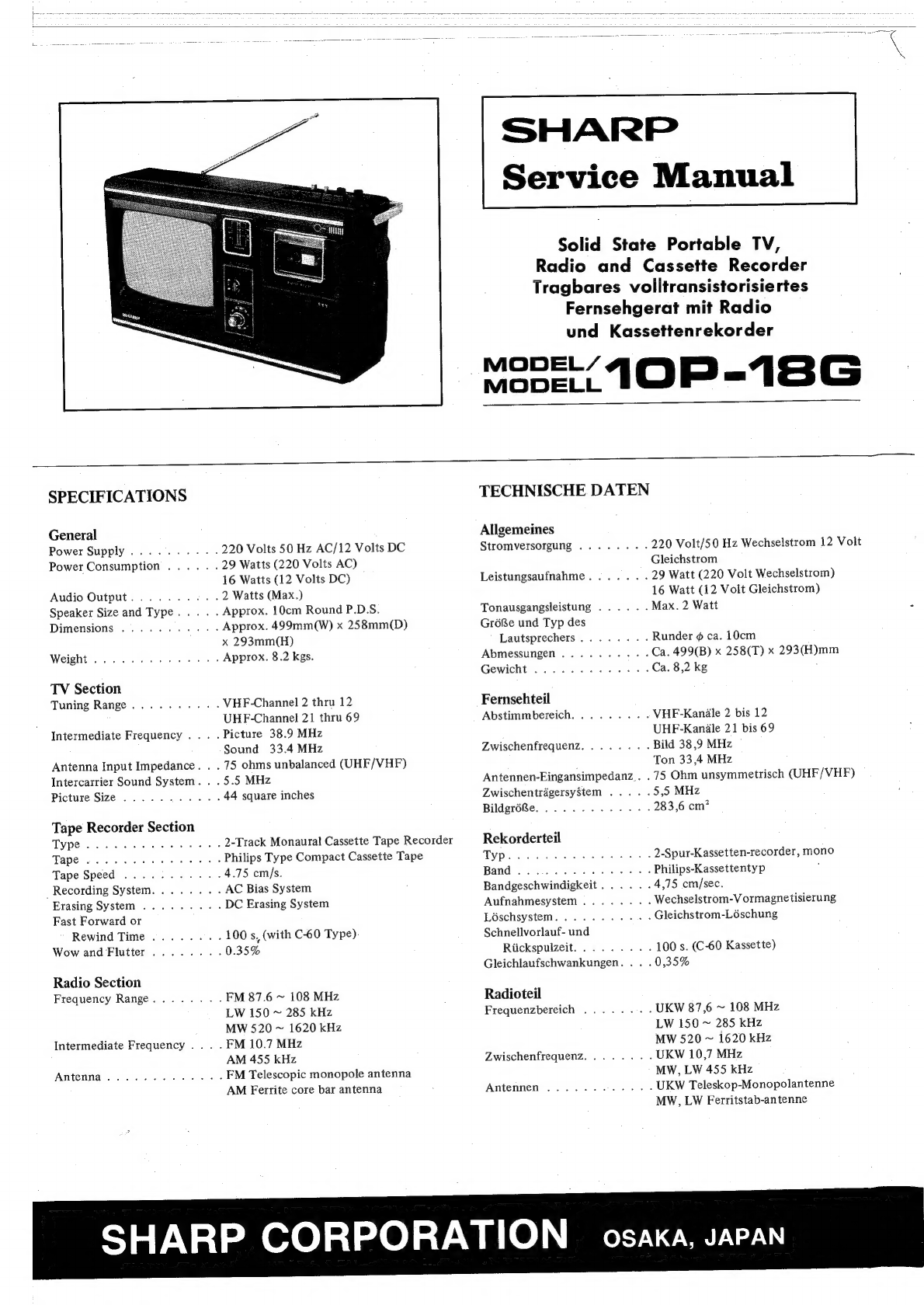
Sharp 10P-18G User manual

Service
Manual
Solid
State
Portable
TV,
Radio
and
Cassette
Recorder
Tragbares
voiitransistorisiertes
Fernsehgerat
mit
Radio
und
Kassettenrekorder
Mope.
IOP
-18G
SPECIFICATIONS
General
Power
Supply.......---
Power
Consumption
....
Audio
Output.......-.
Speaker
Size
and
Type...
.
Dimensions
..........-
TV
Section
Tuning
Range.
........
Intermediate
Frequency
..
.
Antenna
Input
Impedance.
.
Intercarrier
Sound
System.
.
Picture
Size...
....0--
Tape
Recorder
Section
TY
Pens
ou
«Bava
wae
Tape
oc
ce
ee
le ee
Tape
Speed
..........
Recording
System.......
Erasing
System
........
Fast
Forward
or
Rewind
Time
.......
Wow
and
Flutter
.......
Radio
Section
Frequency
Range.......
Intermediate
Frequency...
Antenna..........4..
220
Volts
50
Hz
AC/12
Volts
DC
29
Watts
(220
Volts
AC)
16
Watts
(12
Volts
DC)
2
Watts
(Max.)
Approx.
10cm
Round
P.D.S.
Approx.
499mm(W)
x
258mm(D)
x
293mm(H)
Approx.
8.2
kgs.
VHF-Channel
2
thru
12
UHF-Channel
21
thru
69
.
Picture
38.9
MHz
Sound
33.4
MHz
.
75
ohms
unbalanced
(UHF/VHF)
.5.5
MHz
44
square
inches
2-Track
Monaural
Cassette
Tape
Recorder
Philips
Type
Compact
Cassette
Tape
4.75
cm/s.
AC
Bias
System
DC
Erasing
System
100
s,
(with
C-60
Type).
0.35%
FM
87.6
~
108
MHz
LW
150
~
285
kHz
MW
520
~
1620
kHz
.
FM
10.7
MHz
AM
455
kHz
FM
Telescopic
monopole
antenna
AM
Ferrite
core
bar
antenna
TECHNISCHE
DATEN
Allgemeines
Stromversorgung
........-
220
Volt/50
Hz
Wechselstrom
12
Volt
Gleichstrom
Leistungsaufnahme.......
29
Watt
(220
Volt
Wechselstrom)
16
Watt
(12
Volt
Gleichstrom)
Tonausgangsleistung
......
Max.
2
Watt
a
GréRe
und
Typ
des
Lautsprechers........
Runder
¢
ca.
10cm
Abmessungen..........
Ca.
499(B)
x
258(T)
x
293(H)mm
Gewicht
.........-.5-
Ca.
8,2
kg
Fernsehteil
Abstimmbereich.........
VHE-Kanale
2
bis
12
UHF-Kaniaile
21
bis
69
Zwischenfrequenz........
Bild
38,9
MHz
Ton
33,4
MHz
Antennen-Eingansimpedanz..
.
75
Ohm
unsymmetrisch
(UHF/VHF)
ZwischentrégersyStem
.....
5,5
MHz
BildgréBe..........05.-
283,6
cm?
Rekorderteil
TYPewdag
vd
ee
eae
eg
2-Spur-Kassetten-recorder,
mono
Band
20
ceck
GG
41d
Asc
ee
¥
Philips-Kassettentyp
:
Bandgeschwindigkeit......
4,75
cm/sec.
Aufnahmesystem
........-
Wechselstrom-V
ormagnetisierung
Loschsystem........-5-
Gleichstrom-Léschung
Schnellvorlauf-
und
Riickspulzeit.........
100
s.
(C-60
Kassette)
Gleichlaufschwankungen.
.
.
.0,35%
Radioteil
Frequenzbereich
........
UKW
87,6
~
108
MHz
LW
150
~
285
kHz
MW
520
~
1620
kHz
Zwischenfrequenz........
UKW
10,7
MHz
MW,
LW
455
kHz
Antennen
............
UKW
Teleskop-Monopolantenne
MW,
LW
Ferritstab-antenne
SHARP
CORPORATION
osaka,
JAPAN

Warning:
Operation
of
this
receiver
outside
the
cabinet
or
with
the
covers
removed,
involves
a
shock
hazard
from
the
receiver
power
supplies.
Work
on
the
re-
ceiver
should
not
be
attempted
by
anyone
who
is
not
thoroughly
familiar
with
precautions
necessary
when
working
on
high
voltage
equipment.
Caution:
Do
not
install,
remove,
or
handle
the
picture
tube
in
any
manner
unless
shatterproof
goggles
are
worm.
People
not
so
equipped
should
be
kept
away
while
handling
picture
tube.
Keep
picture
tube
away
from
th
body
while
handling.
Achtung:
Wenn
Sie.
diesen
Empfanger
aufterhalb
des
Ge-
hduses
oder
mit
abgenommenen
Abdeckungen
betrei-
ben,
besteht
beim
Stromversorgungsteil
Kurzschluf-
gefahr.
Wartungsarbeiten
am
Empfanger
diirfen
daher
nur
von
Fachfriften
durchgefiihrt
werden,
die
mit
den
n6tigen
Vorsichtmagnahmen
fiir
Arbeiten
mit
Hochspannung
vertraut
sind.
Vorsicht:
Die
Bildréhre
darf
auf
keinem
Fall
aus-
und
eingebaut
werden,
wenn
keine
nichtsplitternde
Schutz-
brille
getragen
wird.
Nicht
geschiitzte
Personen
miissen
bei
Wartungsarbeiten
an
der
Bildrohre
Ab-
stand
halten.
Halten
Sie
beim
Arbeiten
die
Bildrohre
vom
K6érper
weg.
SAFETY
TEST
If
the
receiver
becomes
damaged
or
has
been
dis-assembled
for
any
reason,
the
following
safety
test
should
be
per-
formed.
1.
Inspect
lead
dress
inside
receiver,
all
leads
should
be
properly
connected
and
wires
and/or
cables
should
not
touch
power
resistors.
2.
Verify
that
all
chassis
insulators
are
properly.
installed
and
are
not
broken.
.
Reassemble
the
receiver
completely.
4.
Connect
the
receiver
to
a
220V,
50Hz
power
outlet
and
turn
“ON”.
5.
A
VTVM,
a
1500
ohm,
1W
resistor
and
a
ground
exten-
sion
lead
with
alligator
clips
at
each
end
are
required
for
making
voltage
measurements.
Set
the
VTVM
to
obtain
readings
on
the
lowest
AC
VOLTS
scale.
Connect
the
ground
lead
of
the
VT
VM
and
one
end
of
the
ground
ex-
tension
lead
to
the
ground
side
of
the
AC
power
outlet
or
a
Known
ground
source
such
as
a
cold
water
pipe.
Connect.
the
1500
ohm
resistor
between
the
other
end
of
the
ground
extension
lead
and
the
tip
of
the
voltage
probe
of
the
VTVM..
AC
voltage
measurements
must
then
be
made
by
firmly
applying
the
tip
of
the
voltage
probe
to
the
following
points:
w
TEST
POINTS
VHF/UHF
ANTENNA
TERMINALS
CONTROL
PANEL,
CHASSIS
MOUNTING
SCREWS
AND
ALL
KNOBS:
If
any
reading
is
higher
than
1.0V
peak.,
the
cause
should
be
immediately
identified
and
corrected.
Reverse
connec-
tion
of
receiver
AC
Line
Cord
Plug
in
the
220V,
50Hz
AC
power
outlet
and
recheck
voltage
readings.
If
any
reading
is
higher
than
1.0V
peak.,
the
cause
should
be
immediately
identified
and
corrected.
SICHERHEITSPRUFUNG
Falls
dex
Empfanger
beschadigt
oder
aus
irgendeinem
Grund
auseinandergebaut
wird,
sollte
die
folgende
Sicher-
heitspriifung
durchgefiihrt
werden.
1.
Die
Leitungsfiihrung
im
Empfanger
iiberpilfen;
simt-
liche
Leitungen
miissen
richtig
angeschlossen
sein
und
Drahte
und/oder
Kabel
diirfen
keine
Leistungswider-
sténde
beriihren.
2.
Sicherstellen,
dafs
alle
Chassis-Isolatoren
richtig
einge-
baut
und
nicht
zerbrochen
sind.
3.
Den
Empfanger
wieder
vollstandig
zusammenbauen.
4.
Den
Netzkabelstecker
des
Empfangers
in
eine
Netz-
steckdose
mit
220V,
50
Hz
stecken
und
das
Gerit
ein-
schalten.
5.
Ein
Rohrenvoltmeter,
ein
Widerstand
mit
1500
Ohm,
iW
und
eine
Erdverlangerungsleitung
mit
Krokodi-
klemmen
an
beiden
Enden
sind
fiir
die
Spannungs-
messungen
erforderlich.
Das
RGhrenvoltmeter
so
ein-
stellen,
da&
die
Anzeige
auf
der
untersten
Netzstrom-
Voltskala
(AC
VOLTS)
erfolgt.
Die
Erdleitung
des
Rohrenvoltmeters
und
ein
Ende
der
Erdverlingerungs-
leitung
mit
der
Erdseite
der
Netzsteckdose
oder
eine
bekannten
Erdquelle,
wie
z.B.
einer
Kaltwasserleitung,
verbinden.
,
Den
1500-Ohm-Widerstand
zwischen
das
andere
Ende
der
Erdverlingerungsleitung
und
die
Spitze
der
Span-
nungsmessungen
miissen
dann
durch
festes
Driicken
der
Spitze
der
Spanngssonde
auf
die
nachstehend
aufge-
fiihrten
Stellen
durchgefiihrt
werden.
PRUFUNG
ZIEGEN
VHF/UHF-ANTENNENKLEMMEN,
BEDIENUNGSPLAT-
TE
CHASSIS,
BEFESTIGUNGSSCHAUBEN
UND
SAMT-
LICHE
KNOPFE:
Bei
einer
Anzeige
von
mehr
als
1,0V
Spitze
sollte
die
Uh-
sache
sofort
ausfindig
gemacht
und
Abhilfe
geschaffen
werden.
Den
Netzadapter
das
Empfangers
umgekehrt
in
die
Netzkabelstecker
mit
220V/50
Hz
stecken
und
die
Spannungsanzeigen
nochmals
iiberpriifen.
Bei
einer
Anzeige
von
mehr
als
1,0V
Spitze
sollte
die
Ursache
sofort
ausfin-
dig
gemacht
und
Abhilfe
geschaffen
werden.

Safety
Check
at
Servicing
1.
Make
repairs
carefully!
1)
When
replacing
the
parts,
be
sure
to
use
the
speci-
fied
ones.
(Fuse,
power
cord,
high
tension
circuit
components,
power
circuit
components,
internal
wir-
ing
leads).
;
2)
At
servicing,
also
check
for
parts
location,
spacing,
wiring,
soldering
and
arrangement
of
insulating
mate-
rials
(tube,
tape,
PVC
sheet
etc.).
2.
Recheck
the
safety
after
repairs!
1)
Make
sure
the
receiver
is
free
from
contamination
of
dust,
solder
chips,
waste
wire,
etc.
2)
Check
for
the
insulation
by
using
a
tester,
etc.
(Be-
tween
terminals
of
AC
plug,
between
the
antenna
ter-
minal
plate
and
exposed
metallic
parts).
3)
Make
sure
the
tuner
cover,
high
tension
box
case,
rear
lid,
bottom
lid,
etc.
have
been
properly
set
in
place.
Let
the
users
have
a
proper
knowledge
to
operate
the
receiver.
TV
SECTION
+B
Voltage
Checking
1.
2;
3.
Connect
the
AC
power
cord
plug
to
a
wall
outlet
(AC
220V,
50
Hz).
Set
the
mode
switch
to
“TV”
position.
Adjust
the
unit
to
produce
normal
picture
and
sound,
then
be
certain
the
+B
voltage
(at
the
emitter
of
Q701)
is
11.5V.
Only
after
that,
proceed
with
the
adjustment
stated
below.
More,
check
that
the
+B
voltage
(at
the
emitter
of
Q701)
for
either
of
the
radio
and
tape
re-
corder
circuits
is
11.0V.
AGC
Adjustment
1.
2:
Set
the
RF
AGC
knob
(R253)
to
“MAX”
position.
Receiving
test
pattern,
adjust
the
local
oscillation
to
get
normal.
.
Setting
the
input
field
intensity
at
60
+
2
dB,
apply
sig-
nal
(50
mV,
1
kHz
+
50
Hz,
sine
wave)
generated
by
CR
oscillator,
to
the
tuner’s
test
point
TP202
through
a
re-
sistor
of
470
ohm
and
capacitor
of
47
wF
connected
in
series.
.
Rotate
the
RF
AGC
knob
(R253)
counterclockwise,
then
there
will
be
developed
ripples
on
an
oscilloscope
(connected
to
the
TP12).
.
Next,
rotate
the
RF
AGC
knob
(R253)
gradually
clock-
wise
and
stop
the
turning
where
the
amount
of
such
ripples
begins
to
reduce
drastically.
.
Set the
input
field
intensity
to
90
+
2
dB
and
check
that
there
is
nothing
abnormal
as
of
cross
modulation,
mis-
sync
and
too
a
strong
contrast.
Sicherheitspriifung
bei
Wartungsarbeiten
1.
Arbeiten
sorgfaltig
ausfiihren!
1)
Beim
Auswechseln
von
Teilen
nur
die
vorgeschriebe-
nen
verwenden.
(Sicherung,
Netzkabel,
Hochspan-
nungsstromkreis-Bauteile,
Arbeitsstromkreis-Bauteile,
innere
Zuleitungen).
2)
Bei
Ausfiihrung
von
Wartungsarbeiten
aufSerdem
die
Lage
der
Teile,
Abstande,
Verdrahtung,
Verlétung
und
Anordnung
der
Isoliermaterielien
(R6hren,
Bander,
PVC-Platten
usw.)
iiberpriifen.
2.
Die
Sicherheit
nach
Ausfihrung
von
Reparaturen
noch-
mals
tiberpriifen!
1)
Darauf
achten,
dai
der
Empfanger
nicht
durch
Staub,
Lotspine,
Drahtreste
usw.
verschmutzt
ist.
2)
Die
Isolierung
mit
Hilfe
eines
Priifgerates
usw.
iiber-
priifen
(zwischen
den
Klemmen
des
Netzkabelfassung,
zwischen
der
Antennenklemmenplatte
und
freilie-
genden
Metallteilen).
3)
Darauf
achten,
daf§
Tunerabdeckung.
Hochspan-
nungsgehduse,
Riickwand,
untere
Platte
usw.
in
rich-
tiger
Lage
angebracht
wurden.
Den
Verwendern
ausreichende
Kenntnisse
iiber
den
Betrieb
des.
Empfangers
beibringen.
FERNSEHGERAT-TEIL
Uberpriifen
der
+B-Spannung
1.
2.
3.
Den
Netzkabelstecker
in
eine
Netzsteckdose
(Wechsele-
strom
220V,
50
Hz)
stecken.
Den
Betriebsartenschalter
auf
“TV”
stellen.
Das
Geradt
auf
normales
Bild
und
normalen
Ton
einstel-
len,
dann
sicherstellen,
da
die
+B-Spannung
(am
Emit-
ter
von
Q701)
11,5V
betrigt.
Erst
danach
die
folgende
Einstellung
vornehmen.
Aufferdem
nachpriifen,
ob
die
+B-Spannung
(am
Emitter
von
Q701)
sowohl
fiir
die
Radio-
als
auch
Tonbandgeratkreise
11,0V
betragt.
Einstellen
des
automatischen
Schwundausgleichs
(AGC)
1.
2.
Den
Knopf
fiir
automatischen
HF-Schwundausgleich
(R253)
auf
“MAX”
stellen.
Bei
Empfang
des
Einstelltafel
die
Einstellung
so
vor-
nehmen,
dafi
die
Empfangsiiberlagerung
normal
ist.
.
Die
Eingangsfeldstirke
auf
60
+
2
dB
einstellen
und
das
durch
den
CR-Schwinger
erzeugte
Signal
(50
mV,
1
kHz,
+50
Hz,
Sinauswelle)
iiber
einen
hintereinandergeschal-
ten
Widerstand
mit
470
Ohm
und
Kondensator
mit
47
uF
dem
Tuner-Priifpunkt
TP202
zuleiten.
.
Den
Knopf
fiir
automatischen
HF-Schwundausgleich
(R253)
entgegen
dem
Uhrzeigersinn
drehen,
so
dai
auf
einem
(an
den
TP12
angeschlossenen)
Oszillographen
Welligkeit
erzeugt
wird.
.
Danach
den
Knopf
fiir
automatischen
HF-Schwundaus-
gleich
(R253)
langsam
im
Uhrzeigersinn
so
lange
drehen,
bis
die
Welligkeit
stark
abzunehmen
beginnt.
.
Die
Eingangsfeldstarke
auf
90
+
2
dB
einstellen
und
nachpriifen,
ob
kein
anormaler
Zustand,
wie
z.B.
Kreuz-
modulation,
Fehlsynchronisierung
oder
zu
starker
Kon-
trast,
festzustellen
ist.

Video
Trap
(CF401)
Checking
1,
2.
3.
Let
the
test
point
(TP201)
be
grounded.
Set
the
contrast
and
brightness
controls
respectively
to
“MAX”
position.
Apply
signal
(5.5
MHz,
100
dB,
non-modulated)
pro-
duced
by
a
signal
generator,
to
the
TP12
through
a
capa-
citor
of
0.01
pF.
.
Connect
an
oscilloscope,
via
a
capacitor
of
5
pF,
to
the
cathode
of
CRT
and
check
that
the
wave
amplitude
of
5.5
MHz
signal
is
below
0.3Vp-p.
Note:
The
oscilloscope
to
be
used
must
be
the
one
having
the
performance
that
the
input
impedance
is
1M
ohm,
input
capacitance;
below
15
pF,
band
width;
more
than
10
MHz.
VERTICAL
AND
HORIZONTAL
CIRCUIT
ALIGNMENT
Rough
Adjustment
of
Each
Section
1.
2.
3.
Set
the
AC
line
voltage
to
220
volts.
Receive
at
test
pattern
in
normal
operating
receiver
con-
dition.
Rotate
the
Brightness
and
contrast
controls
to
maximum
clockwise.
.
Adjust
the
H-Hold
coil
(L601)
to
synchronize
the
pic-
ture
horizontally.
.
Set
the
V-Hold
control
(R510)
to
synchronize
the
pic-
ture
vertically.
.
Adjust
the
V-Lin
(R508)
and
V-Size
(R505)
controls
to
the
best
vertical
linearity
and
picture
size.
.
Both
horizontal
and
vertical
centering
are
accomplished
by
rotating
the
centering
rings
mounted
on
the
rear
of
the
deflection
yoke
assembly.
Vertical
circuit
adjustment
1
wn
Adjust
the
V-linearity
control
(R508)
so
that
the
picture
is
symmetrical
in
up-and-down
direction
having
the
best
linearity.
.
Adjust
the
V-Size
control
(R505)
to
set
the
over-scan-
ning
to
9.5
+
2%.
.
Rotate
the
V-Hold
control
(R510)
clockwise
and/or
counterclockwise
to
see
that
the
picture
is
not
deviated
on
either
side
of
the
screen.
.
Set
the
V-Hold
control
(R510)
to
its
“Center”
position.
.
Upon
completion
of
the
above
adjustment,
see
there
ap-
pears
no
crossover
distortion
(no
white
horizontal-bar
at
the
center
of
screen).
Uberpriifen
der
Videosperre
(CF401)
1.
2:
3
Den
Priifpunkt
(TP201)
an
Erde
legen.
Den
Kontrast-
und
Helligkeitsregler
jeweils
auf
“MAX”
einstellen.
.
Ein
durch
einen
Mefsender
erzeugtes
Signal
(5,5
MHz.
100
dB
nicht
moduliert)
iiber
einen
Kondensator
mit
0,01
uF
dem
TP12
zuleiten.
.
Einen
Oszillographen
iiber
einen
Kondensator
mit
5
pF
an
die
Kathode
der
Kathodenstrahlréhre
anschliefen
und
nachpriifen,
ob
die
Wellenamplitude
des
5,5
MHz.
Signals
unten
0,3Vss
liegt.
Zur
Beachtung:
Der
verwendete
Oszillograph
muf
eine
Eingangsimpe-
damz
von
1M
Ohm,
eine
Eingangskapazitit
von
wenige:
als
15
pF
und
eine
Bandbreite
von
mehr
als
10
MHz
haben.
ABSTIMMUNG
DES
VERTIKAL-
UND
HORIZONTAL-STROMKREISE
Grobeinstellung
jedes
Teils
1.
23
3.
Die
Netzspannung
auf
220
Volt
einstellen.
Bei
normalem
Betriebszustand
des
Empfangers
ein
Priif.
bild
empfangen.
Die
Regler
fiir
Helligkeit
und
Kontrast
bis
zum
Anschlag
im
Uhrzeigersinn
drehen.
.
Die
bildfangspule
(L601)
einstellen,
um
das
Bild
hori-
zontal
zu
synchronisieren.
.
Den
Bildfangregler
(R510)
einstellen,
um
das
Bild
verti.
kal
zu
synchronisieren.
.
Die
Regler
fiir
Bildlinearitét
(R508)
und
Bildhdhe
(R505)
auf
die
beste
Bildlinearitét
und
BildhGhe
einstellen.
.
Sowohl
die
horizontale
als
auch
vertikale
Zentrierung
wird
durch
Drehen
der
Zentrierringe
erzielt,
die
an
de1
Riickseite
der
Ablenkjocheinheit
befestigt
sind.
Einstellen
des
Vertikalkreises
1.
Den
Bildlinearitatsregler
(R508)
so
einstellen,
daf
da;
Bild
nach
oben
und
unten
symmetrisch
ist
und
die
beste
Linearitat
hat.
.
Den
Bildhéhenregler
(R505)
auf
eine
Ubertastung
von
9,5
+
2%
einstellen.
.
Den
Bildfangregler
(R510)
im
und/oder
entgegen
dem
Uhrzeigersinn
drehen,
um
das
Bild
auf
dem
Bildschirm
mittig
einzustellen.
;
.
Den
Bildfangregler
(R510)
auf
seine
Mittelstellung
ein.
stellen.
.
Nach
der
obigen
Einstellung
priifen,
da’
keine
Uber.
kreuzungsverzerrung
(kein
weifser
horizontaler
Balken
in
der
Bildschirmmitte)
auftritt.

H-Hold
and
H-Size
adjustment
1.
2
Get
the
unit
ready
to
receive
TV
signals.
Once
rotate
the
shaft
of
the
H-Hold
coil
(L601)
counter-
clockwise
to
let
the
picture
collapse,
then
rotate
it
clock-
wise
until
the
picture
again
assumes
its
normal
state:
consider
the
pattern
center
of
the
picture
thus
attained
to
be
a
point
“a”.
Further
rotate
the
coil
clockwise
to
have
the
picture
again
fall
down
and
after
that,
rotate
it,
in
turn,
counterclockwise
so
that
the
picture
assumes
the
normal
state
once
again:
consider
this
pattern
center
to
be
a
point
“‘b”.
Now,
rotate
the
shaft
of
the
H-Hold
coil
in
such
a
way
that
the
pattern
center
gets
in
the
middle
between
the
two
points
“a’’
and
“‘b”,
remove
the
coil’s
shaft
taking
care
to
keep
ie
core
be
just
in
a
stop.
Fin-
ally,
insert
the
shaft
into
the
core
and
make
the
stopper
be
locked:
for
the
insertion,
be
sure
to
have
the
shaft’s
projection
face
just
upwards.
CHASSIS
REMOVAL
Whenever
it
becomes
necessary
to
remove
the
chassis
from
the
cabinet,
proceed
in
the
following
manner.
1.
2.
Nn
w
Remove
the
seven
screws
(A)
from
the
back
cabinet.
Pull
out
the
VHF/UHF
channel
Selector
and
Tuning
knob
from
the
front
cabinet.
.
Pull
out
the
main
chassis.
.
Remove
the
one
screw
from
the
Transformer
angle.
.
Remove
the
one
screw
©
from
the
Tuner
angle.
.
Remove
the
CRT
socket
(D
coating
earth
lead
©
and
anode
cap
®
:
.
Loosen
the
deflection
yoke
cramping
screw
©
and
pull
the
deflection
yoke
out
of
the
CRT
neck.
.
Pull
out
the
Radio
Tuning
knob,
Tone
and
Volume
knob
from
the
front
cabinet.
.
Remove
the
five
screws
(H)
from
the
Radio
and
Cas-
sette
unit.
—
Figure
1
Abb.
1
Zeilenfang-
und
Bildbreiteneinstellung
1.
2:
Das
Geraét
auf
den
Empfang
von
Fernsehsignalen
ein-
stellen.
Die
Achse
der
Zeilenfangspule
(L601)
einmal
entgegen
dem
Uhrzeigersinn
drehen,
damit
das
Bild
zusammen-
fallt,
dann
diese
Spule
im
Uhrzeigersinn
drehen,
bis
der
normal
Bildzustand
wiederhergestellt
ist.
Dabei
ist
die
Rastermitte
des
auf
diese
Weise
erzielten
Bilds
als
Punkt
2
anzunehmen.
Die
Spule
im
Uhrzeigersinn
weiter-
drehen,
damit
das
Bild
wieder
zusammenfallt,
dann
ent-
gegen
dem
Uhrzeigersinn
drehen,
um
den
normalen
Bild-
zustand
wiederherzustellen.
Dabei
ist
diese
Rastermitte
als
Punkt
,,b”
anzunehmen.
Danach
die
Achse
der
Zei-
lenfangspule
so
drehen,
dafs
sich
die
Rastermitte
zwischen
die
beiden
Punkte
,,a”
und
,,b”
bewegt,
die
Spulenachse
entfernen
und
dabei
darauf
achten,
daf
der
Kern
ein-
gerastet
bleibt.
Schlief&lich
die
Achse
in
den
Kern
stecken
und
den
Anschlag
einrasten,
dabei
mufs
die
Vor-
sprungflaiche
der
Achse
nach
oben
weisen.
ENTFERNEN
DES
CHASSIS
Falls
das
Chassis
vom
Gehduse
entfernt
werden
ne
auf
die
nachstehend
beschriebene
Weise
vorgehen.
ty
2.
Die
sieben
Schrauben
(A)
von
der
Gehiuseriickseite
ent-
fernen.
Den
VHF
/UHF-Kanalwahler
und
Abstimmknopf
aus
der
Gehausevorderseite
ziehen.
.
Hauptgehause
herausziehen.
.
Eine
Schraube
vom
Netztransformatorwinkel
ent-
fernen.
.
Eine
Schraube
©
vom
Tunerwinkel
entfernen.
.
Die
Kathodenstrahlrohrenfassung
oO,
isolierte
Erdlei-
tung
(©
Anodenkappe
®
entfernen.
.
Die
Ablenkjoch-Klemmschraube
G)
ldsen
und
das
Ab-
lenkjoch
aus
dem
Kathodenstrahlrahrenhals
ziehen.
.
Den
Sendereinstellung
knopf
und
Klang
und
Lautstarker
knopf
aus
der
Gehdusevorderseite
ziehen.
.
Die
fiinf
Schrauben
(H)
vom
Tragbares
Volltransistori-
siert
entfernen.
Figure
2
Abb.
2

Figure
3
Abb.
3
Cautions
on
Replacement
of
Telescopic
Antenna
When
replacing
the
telescopic
antenna
(QANTROOL3TAZZ)
with
a
new
one,
observe
the
following.
1.
Assemble
the
components
together
as
shown
below.
2.
Clamp
the
nut
with
an
appropriate
torque.
3.
After
clamping
the
nut,
apply
adhesive
agent
to
its
top
to
prevent
it
from
loosening.
(1)
Telescopic
antenna
(2)
Plain
washer
(A)
(3)
Cabinet
(4)
Antenna
angle
(5)
Spring
washer
(6)
Plain
washer
(B)
(7)
Plain
washer
(C)
(8)
Lock
nut
(1)
Teleskopantenne
(2)
Flache
Unterlagscheibe
(A)
(3)
Gehause
(4)
Antennenwinkel
(5)
Federnde
Unterlagscheibe
(6)
Flache
Unterlagscheibe
(B)
(7)
Flache
Unterlagscheibe
(C)
(8)
Sicherungsmutter
Abb.
4
VorschtsmaSregeln
fiir
das
Auswechseln
der
Teleskop-
antenne
Beim
Ersetzen
der
Teleskopantenne
(QANTRO013TAZZ)
durch
eine
neue
die
folgenden
Punkte
beachten.
1.
Die
Bauteile
gema&
folgender
Abbildung
zusammen-
bauen.
2.
Die
Mutter
mit
einem
geeigneten
Drehmoment
fest-
ziehen.
3.
Nach
Festziehen
der
Mutter
auf
deren
Oberseite
Klebe-
mittel
auftragen,
damit
sich
diese
nicht
lost.
Adhesive
agent
Klebemittel
Figure
5
Abb.
5

PIX
IF
Adjustment
1.
Apply
signal
produced
by
a
signal
generator,
to
the
test
point
TP203
through
a
resistor
of
470
ohm
and
capaci-
tor
of
0.01
uF
connected
in
series.
.
Connect
the
input
of
an
oscilloscope
to
the
test
point
TP12.
.
Externally
apply
about
DC
4V
(the
value
about
20
dB
lower
than
that
for
the
maximum
sensitivity)
to
the
test
point
TP201
and
have
the
test
point
TP204
be
grounded.
.
Adjust
the
core
of
T205
so
as
to
attain
the
maximum
value
at
the
point
“P”’.
.
Adjust
the
adjacent
sound
trap
(T202)
and
sound
trap
(T206)
to
their
proper
level,
and
further
adjust
the
cores
of
T203
and
T204
so
that
the
respective
waveforms
reach
the
maximum
as
shown
in
Fig.
6.
.
Apply
signal
produced
by
the
sweep
generator,
to
the
test
point
TP101
through
a
resistor
of
470
ohm
and
capacitor
of
0.01
uF
connected
in
series.
.
Externally
apply
about
DC
4V
(the
value
about
20
dB
lower
than
that
for
the
maximum
sensitivity)
to
the
test
point
TP201
and
let
the
test
point
TP204
be
grounded.
.
Readjust
the
adjacent
sound
trap
(T202)
and
sound
trap
(T206)
respectively
to
40.4
MHz
and
33.4
MHz.
.
Adjust
the
cores
of
T101
(at
tuner
side)
and
T201
(at
PIX
IF
side)
so
that
overall
waveform
becomes
as
shown
in
Fig.
7:
the
adjustment
must
be
done
in
such
a
way
as
to
provide
the
maximum
sensitivity.
Adj.
S
P:
38.9
MHz
S:
33.4
MHz
Adj.
S:
40.4
MHz
Figure
6
Abb.
6
Bild-ZF
Einstellung
1.
Das
durch
einen
Mefisender
erzeugte
Signal
iiber
einen
hintereinandergeschalteten
Widerstand
mit
470
Ohm
und
Kondensator
mit 0,01
uF
dem
Priifpunkt
TP203
zuleiten.
.
Den
Eingang
eines
Oszillographen
mit
dem
Priifpunkt
TP12
verbinden.
.
Dem
Priifpunkt
TP201
von
aufen
ungefahr
4V
Gleich-
strom
(ein
um
ungefahr
20
dB
niedriger
Wert
als
derje-
nige
bei
maximaler
Empfindlichkeit)
zuleiten
und
den
Priifpunkt
TP204
an
Erde
legen.
.
Den
Kern
von
T205
so
einstellen,
daf{i
der
Héchstwert
bei
Punkt
,,P”’
erreicht
wird.
.
Die
benachbarten
Tonsperren
(T202
und
T206)
auf
ihren
richtigen
Pegel
einstellen
und
die
Kerne
von
T203
und
T204
so
verstellen,
daf
die
jeweiligen
Wellenformen
gemaf
Abb.
6.
ihr
Maximum
erreichen.
.
Das
durch
den
Kippgenerator
erzeugte
Signal
iiber
einen
hintereinandergeschalteten
Widerstand
mit
470
Ohm
und
Kondensator
mit
0,01
wF
dem
Priifpunkt
TP101
zu-
leiten.
.
Dem
Priifpunkt
von
aufen
ungefahr
4V
Gleichstrom
(ein
um
ungefahr
20
dB
niedrigerer
Wert
als
derjenige
bei
maximaler
Empfindlichkeit)
zuleiten
und
den
Priifpunkt
TP201
und
TP204
an
Erde
legen.
.
Die
benachbarten
Tonsperren
(T202
und
T206)
jeweils
auf
40,4
MHz
und
33,4
MHz
einstellen.
.
Die
Kerne
von
T101
(Tuner-Seite)
und
T201
(Bild-ZF-
Seite)
so
einstellen,
dai
sich
eine
Gesamtwellenform
ge-
mafR§
Abb.
7.
ergibt;
diese
Einstellung
mu
so
vorgenom-
men
werden,
daf§
die
maximale
Empfindlichkeit
erzielt
wird.
Adj.
S
RP
38.9
MHz
=:
33.4
MHz
Adj.
S:
40.4
MHz
Figure
7
Abb.
7

Sound
IF
Adjustment
(The
screwdriver
to
be
used
must
be
non-metallic.)
1.
2.
Have
the
PIF
AGC
testing
point
(TP201)
be
grounded.
Apply
signal
(5.5
MHz,
100%
frequency-modulated
at_
modulation
frequency
200
Hz)
produced
by
a
signal
generator,
to
the
test
point
TP12
through
a
capacitor
of
0.01
uF.
.
Connect
an
oscilloscope
to
the
test
point
TP301.
(The
oscilloscope
is
preferred
to
be
used
in
combination
with
a
VIVM.)
.
Set the
output
of
signal
generator
at
100
dB
and
adjust
the
core
of
L301
so
that
the
waveform
of
the
detected
output
becomes
free
from
distortion,
having
the
maxi-
mum
amplitude.
.
Keeping
the
signal
generator’s
output
at
100
dB,
further
adjust
the
core
of
L301
so
that
waveform
of
the
detect-
ed
output
becomes
free
from
noises,
and
with
the
maxi-
mum
amplitude.
AUDIO
SECTION
+B
Voltage
Checking
1.
2:
Set
AC
line
voltage
at
220V,
50
Hz.
Set
the
mode
switch
to
“RADIO”
or
“TAPE”
position
and
be
certain
the
voltage
at
the
collector
of
QBO7
(or
at
the
emitter
of
Q703)
is
11.0
+
0.5V.
Here,
the
volume
and
tone
controls
must
have
been
set
to
“MAX”
posi-
tion
respectively
(with
a
resistor
of
16
ohm
connected
to
the
speaker
terminal).
FM
IF
Adjustment
(The
screwdriver
to
be
used
must
be
non-metallic.)
1.
Set
the
mode
switch
to
“RADIO”
position,
the
radio
band
switch
to
“FM”
position
and
AFC
selector
switch
to
“OFF”
position.
.
Connect
the
output
of
sweep
generator
to
the
LAO3
is
M-form
coupling.
.
Connect
the
input
of
sweep
generator
to
the
TP-A9
(hot
side)
and
to
the
TP-A11
(earth
side).
.
Rotate
the
radio
tuning
knob
to
tune
in
the
vicinity
of
the
highest
frequencies
(with
the
variable
capacitor
set
to
around
“MIN”
position)
and
loosen
the
core
of
TAOS.
.
Reduce
the
output
of
sweep
generator
to
the
extent
enough
to
provide
the
waveform
as
shown
in
Fig.
8.
.
Adjust
the
cores
of
TAO1,
TAO3
and
TA04
to
achieve
correct
IF
waveform:
that
is,
adjust
each
of
the
cores
so
that
there
will
be
a
good
single
peak
response
and
right-
to-left
symmetry,
as
shown
in
Fig.
8.
.
Let
the
unit
operate
on
DC
power
source,
reduce
the
DC
voltage
to
the
specified
value
to
see
that
there
is
nothing
abnormal
in
waveforms.
After
the
checking,
restore
the
AC
operation.
Ton-ZF-Einstellung
(Der
verwendete
Schraubenzieher
mu8
nichtmetallisch
sein.)
1.
2.
Den
Bild-ZF-Schwundausgleichautomatik-Priifpunkt
(TP
201)
an
Erde
legen.
Das
durch
einen
Mefisender
erzeugte
Signal
(5,5
MHz,
bei
einer
Modulationsfrequenz
von
200
Hz
100%
fre-
quenzmoduliert)
iiber
einen
Kondensator
mit
0,01
uF
dem
Priifpunkt
TP12
zuleiten.
.
Einen
Oszillographen
mit
dem
Priifpunkt
TP301
verbin-
den.
(Der
Oszillograph
sollte
méglichst
zusammen
mit
einem
Rohrenvoltmeter
verwendet
werden.)
.
Den
Ausgang
des
MeSsenders
auf
100
dB
einstellen
und
den
Kern
von
L301
so
justieren,
dafs
die
Wellenform
des
angezeigten
Ausgangs
verzerrungsfrei
ist
und
die
maxi-
male
Amplitude
hat.
.
Den
Ausgang
des
Mefisenders
auf
100
dB
halten
und
den
Kern
von
L301
so
verstellen,
dafs
die
Wellenform
des
an-
gezeigten
Ausgangs
storungsfrei
ist
und
die
maximale
Amplitude
hat.
TON-TEIL
Uberpriifen
der
+B-Spannung
1.
2:
Die
Netzspannung
auf
220V,
50
Hz
einstellen.
Den
Betriebsartenschalter
auf
,.RADIO”
oder
,,TAPE”
einstellen
und
darauf
achten,
dafi
die
Spannung
am
Kol-
lektor
von
QBO7
(oder
am
Emitter
von
Q703)
11,0
+
0,5V
betragt.
Dabei
miissen
die
Lautstarke-
und
Klang-
regler
jeweils
auf
,MAX”’
eingestellt
werden.
(Dabei
ist
ein
Widerstand
mit
16
Ohm
an
den
Lautsprecheran-
schlu8&
angeschlossen.)
UKW-ZF-Einstellung
(Der
verwendete
Schraubenzieher
muf
nichtmetallisch
sein.)
Ls
Den
Betriebsartenschalter
auf
,.RADIO”’,
den
Wellen-
bereichsschalter
auf
,FM”
und
den
Wahlschalter
fiir
automatische
Scharfabstimmung
(AFC)
auf
,,OFF”
stellen.
.
Den
Ausgang
des
Kippgenerators
in
M-formiger
Kopp-
lung
mit
LAO3
verbinden.
.
Den
Eingang
des
Kippgenerators
mit
TP-A9
(spannungs-
fiihrende
Seite)
und
TP-Al1
(Erdungsseite)
verbinden.
.
Den
Sendereinstellknopf
drehen,
um
in
der
Nahe
der
héchsten
Frequenzen
abzustimmen
(der
Drehkondensa-
tor
steht
ungefahr
auf
,,MIN”’),
und
den
Kern
von
TAOS
lésen.
.
Den
Ausgang
des
Kippgenerators
so
weit
reduzieren,
dafs
sich
die
in
Abb.
8
gezeigte
Wellenform
ergibt.
.
Die
Kerne
von
TAO1,
TAO3
und
TA04
so
einstellen,
daf
die
richtige
ZF-Wellenform
erzielt
wird,
das
heift,
jeder
der
Kerne
ist
so
einzustellen,
dafi
sich
eine
gute
Einzel-
spitze
und
Rechts-Links-Symmetrie
gema8
Abb.
8
ergibt.
.
Das
Gerit
tiber
eine
Gleichstromquelle
betreiben
und
die
Gleichspannung
auf
den
vorgeschriebenen
Wert
reduzie-
ren,
um
sicherzustellen,
da
die
Wellenformen
normal
sind.
Nach
dieser
Uberpriifung
das
Gerit
wieder
iiber
Netzstrom
betreiben.

8.
9.
Adjust
the
core
of
TAOS
to
obtain
S-curve
characteris-
tic
as
shown
in
Fig.
9,
say,
symmetrical
in
both
up-and-
down
and
right-to-left
directions.
Like
in
the
step
7,
reduce
the
AC
voltage
to
see
that
there
is
no
abnormality.
10.7MHz
Figure
8
Abb.
8
AM
IF
Adjustment
(The
screwdriver
to
be
used
must
be
non-metallic.)
1.
Set
the
mode
switch
to
“RADIO”
position,
the
radio
band
switch
to
“MW”
position
and
AM
selectivity
selec-
tor
switch
to
“DX”
position.
.
Connect
a
standard
loop
antenna
to
the
output
of
sweep
generator
and
further
connect
it
to
the
MW
coil
of
bar
antenna
in
M-form
coupling.
(The
distance
between
the
loop
antenna
and
bar
antenna
must
be
approx.
10
cm.)
.
Connect
the
input
of
sweep
generator
between
the
TP-
A10
and
TP-Al1
(earth)
through
a
capacitor
of
1
uF
(to
cut
off
the
DC
component).
.
Rotate
the
radio
tuning
knob
to
tune
in
the
vicinity
of
the
highest
frequencies
(with
the
variable
capacitor
set
to
around
“MIN”
position).
.
Reduce
the
output
of
sweep
generator
to
become
low
enough
to
provide
the
waveform
level
as
shown
in
Fig.
10.
.
Adjust
the
cores
of
CF3,
TPO2
and
TAOQ3
so
that
IF
waveform
becomes
as
shown
in
Fig.
10:
the
waveform
then
must
be
symmetrical
in
right-to-left
direction
with
the
best
sensitivity.
.
Letting
the
unit
to
operate
on
DC
power
source
and
re-
duce
the
DC
voltage
down
to
the
specified
value
to
see
that
there
is
nothing
abnormal
caused
in
waveforms:
after
this
checking,
restore
the
AC
operation.
More,
vary
the
tuning
band
over
from
fy
to
fy,
to
check
that
there
is
no
distortion
of
waveform:
pay
particular
regard
to
the
band
in
the
vicinity
of
910
kHz
to
1,365
kHz.
8.
Den
Kern
von
TAOS
so
einstellen,
dafi
die
in
Abb.
9
ge-
zeigte
S-Kurvencharakteristik,
symmetrisch
von
oben
nach
unten
und
rechts
nach
links,
erzielt
wird.
9.
Wie
bei
Schritt
7
die
Netzspannung
reduzieren,
um
nach-
zuprifen,
da
kein
anormaler
Zustand
vorhanden
ist.
10.7MHz
Figure
9
Abb.
9
AM-ZF-Einstellung
(Der
verwendete
Schraubenzieher
muf
nichtmetallisch
sein.)
1.
Den
Betriebsartenschalter
auf
,RADIO”,
den
Wellen-
bereichsschalter
auf
,MW’
und
den
AM-Empfindlich-
keitswahlschalter
auf
,.DX”
stellen.
.
Eine
normale
Rahmenantenne
mit
dem
Ausgang
des
Kippgenerators
sowie
mit
der
MW-Spule
der
Stabantenne
in
M-formiger
Kopplung
verbinden.
(Der
Abstand
zwischen
der
Rahmenantenne
und
Staub-
antenne
mufi
ca.
10
cm
betragen.)
.
Den
Eingang
des
Kippgenerators
iiber
einen
Kondensator
mit
1
uF
(zum
Unterdriicken
des
Gleichstrombestand-
teils)
zwischen
TP-A10
und
TP-A11
(Erdung)
schalten.
.
Den
Sendereinstellknopf
drehen,
um
in
der
Nahe
der
hochsten
Frequenzen
abzustimmen
(dabei
ist
der
Dreh-
kondensator
auf
ungefuhr
,,.MIN”
einzustellen).
.
Den
Ausgang
des
Kippgenerators
so
weit
reduzieren,
dafs
sich
der
in
Abb.
10
gezeigte
Wellenformpegel
ergibt.
.
Die
Kerne
von
CF3,
TP02
und
TAO3
so
einstellen,
daw
sich
die
in
Abb.
10
gezeigte
Wellenform
ergibt,
die
Wellenform
muf§
bei
bester
Empfindlichkeit
von
rechts
nach
links
symmetrisch
sein.
.
Das
Gerit
tiber
eine
Gleichstromquelle
betrieben
und
Salis
Gleichspannung
auf
den
vorgeschriebenen
Wert
reduzie-
ren,
um
nachzupriifen,
ob
die
Wellenformen
normal
sind;
nach
dieser
Uberpriifung
das
Gerit
wieder
tiber
Netz-
strom
betreiben.
Aufferdem
den
Abstimmbereich
von
fy
auf
f,
andern,
um
nachzupriifen,
ob
die
Wellenform
verzerrt
ist;
dabei
ist
besonders
der
Bereich
in
der
Nahe
von
910
bis
1.365
kHz
zu
beachten.

455kHz
Figure
10
Abb.
10
FM
Tracking
(The
screwdriver
to
be
used
must
be
non-metallic.)
1.
2.
Take
the
same
step
1.
as
of
the
before-mentioned
FM
IF
adjustment.
Connect
a
standard
dummy
antenna
to
a
signal
generator
(75
ohm
input
impedance
for
the
receiver
side),
and
further
connect
one
of
its
two
terminals
to
the
rod
an-
tenna
terminal
K71
and
another
to
the
earth
testing
point
TP-A12.
.
Connect
a
VIVM
to
the
speaker
output
terminal
via
a
resistor
of
16
ohm.
.
Regulate
the
output
level
of
signal
generator
to
be
30dB,
22.5
kHz
frequency-modulated
at
modulation
frequency
400
Hz.
.
Set
the
signal
generator
to
87.25
MHz.
Rotate
the
radio
tuning
knob
to
tune
in
the
lowest
frequencies
(with
the
variable
capacitor
set
to
“MAX”
position),
then
adjust
the
core
of
LAO2
to
attain
the
maximum
output:
for
this
adjustment,
the
maximum
output
should
never
be
taken
for
that
at
the
side
peaks.
The
volume
control
must
have
been
lowered
down
to
the
point
which
doesn’t
enable
the
audio
output
to
saturate.
.
Set
the
signal
generator
to
109
MHz.
Rotate
the
radio
tuning
knob
to
tune
in
the
highest
frequencies
(with
the
variable
capacitor
set
to
“MIN”
position),
then
adjust
the
trimmer
(CA14)
of
the
variable
capacitor
which
is
coupled
in
parallel
with
the
LAO2,
to
achieve
the
maxi-
mum
output.
Also
here,
this
maximum
output
should
never
be
taken
for
that
at
the
side
peaks.
.
Repeat
the
steps
5.
and.6.
until
the
coverage
in
reception
will
be
87.25
MHz
to
109.MHz.
Upon
completion
of
this
frequency
coverage
work,
finish
it
up
by
adjusting
the
said
trimmer
again.
.
Set
the
signal
generator
to
90
MHz
and
rotate
the
radio
tuning
knob
to
tune
in
this signal.
Reduce
the
output
of
signal
generator
until
it
gets
out
of
a
limiter’s
operating
effect
and
adjust
the
core
of
LAO1
to
achieve
the
maxi-
mum
output.
UKW
Abtastung
(Der
verwendete
Schraubenzieher
muf
nichtmetallisch
sein.)
1.
2.
GemafS
Schritt
1.
der
obenbeschriebenen
UKW-ZF-Ein-
stellung
vorgehen.
Eine
normale
Kunstantenne
an
einen
Mefssender
(75
Ohm
Eingangsimpedanz
fiir
die
Empfangerseite)
an-
schlieSen
und
eine
ihrer
beiden
Klemmen
mit
dem
Stab-
antennenanschlufi
K71
sowie
die
andere
Klemme
mit
dem
Erdungspriifpunkt
TP-A12
verbinden.
.
Ein
Rohrenvoltmeter
iiber
einen
Widerstand
mit
16
Ohm
an
die
Lautsprecherausgangsklemme
anschliefen.
.
Den
Ausgangspegel
des
Mefsenders
auf
30
dB,
22,5
kHz
frequenzmoduliert
bei
einer
Modulationsfrequenz
von
400
Hz
einregeln.
.
Den
MeSisender
auf
87,25
MHz
einstellen.
Den
Sender-
einstellknopf
drehen,
um
die
niedrigsten
Frequenzen
ab-
zustimmen
(der
Drehkondensator
steht
auf
,.MAX’’),
dann
den
Kern
von
LAOQ2
so
verstellen,
dafs
der
maxi-
male
Ausgang
erzielt
wird;
bei
dieser
Einstellung
sollte
der
maximale
Ausgang
niemals
als
derjenige
der
Seiten-
spitzen
genommen
werden.
Der
Lautstairkeregler
mu
so
weit
zuriickgedreht
werden,
dafs
der
Tonausgang
nicht
gesattigt
wird.
.
Den
Mef§sender
auf
109
MHz
einstellen.
Den
Senderein-
stellknopf
drehen,
um
die
hdéchsten
Frequenzen
abzu-
stimmen
(der
Drehkondensator
steht
auf
,,MIN”),
dann
den
Trimmer
(CA14)
des
Drehkondensators,
der
mit
LA02
parallelgekoppelt
ist,
auf
maximalen
Ausgang
ein-
stellen.
Auch
hier
sollte
der
maximale
Ausgang
niemals
als
derjenige
der
Seitenspitzen
genommen
werden.
.
Die
Schritte
5.
und
6.
wiederholen,
bis
der
Empfangs-
’
bereich
87,25
bis
109
MHz
betragt.
Nach
dieser
Fre-
—10—
quenzbereichseinstellung
die
endgiiltige
Einstellung
durch
Nachjustieren
des
erwahnten
Trimmers
vor-
nehmen.
.
Den
Mefisender
auf
90
MHz
einstellen
und
den
Sender-
einstellknopf
drehen,
um
dieses
Signal
abzustimmen.
Den
Ausgang
des
Mefisenders
reduzieren,
bis
er
aufer-
halb
des
Begrenzer-Wirkungsbereiches
liegt,
dann
den
Kern
von
LAO]
auf
maximalen
Ausgang
einstellen.

9.
10.
Set
the
signal
generator
to
106
MHz
and
rotate
the
radio
tuning
knob
to
tune
in
this signal.
As
in
the
step
8,
re-
duce
the
signal
generator’s
output
and
adjust
the
trimmer
(CAOS5)
which
is
coupled
in
parallel
with
the
LAO1,
to
attain
the
maximum
output.
Repeat
the
steps
8.
and
9.
to
reach
a
perfect
tracking.
Upon
completion
of
this
tracking,
finish
it
up
by
adjust-
ing
the
said
trimmer
again.
MW
Tracking
3
(The
screwdriver
to
be
used
must
be
non-metallic.)
1.
2.
10.
Take
the
same
procedure
as
of
“AM
IF
Adjustment
1.”.
Connect
a
standard
loop
antenna
to
the
signal
generator
and
positionally
arrange
the
loop
antenna
and
MW
coil
-of
the
bar
antenna
as
shown
in
Fig.
11.
.
Connect
VTVM
to
the
output
terminal
of
speaker
through
a
resistor
of
16
ohm.
.
Set
the
signal
generator
to
be
approx.
70
dB,
30%
fre-
quency-modulated
‘at
modulation
frequency
400
Hz.
‘Next,
set
the
volume
control
to
“MAX”
position
and
ad-
just
the
output
of
signal
generator
to
have
the
sound
output
be
50
mW.
.
Set
the
signal
generator
to
515
kHz
and
rotate
the
radio
tuning
knob
to
tune
in
the
lowest
frequencies,
adjust
the
core
of
TA08
to
provide
the
maximum
output.
.
Set
the
signal
generator
to
1,650
kHz
and
rotate
the
radio
tuning
knob
to
tune
in
the
highest
frequencies.
Then,
adjust
the
trimmer
(CA62)
of
the
variable
capaci-
tor
which
is
coupled
in
parallel
with
the
TA08,
to
pro-
vide
the
maximum
output.
.
Repeat
the
steps
5.
and
6.
until
the
frequency
coverage
will
range
from
515
kHz
to
1,650
kHz.
Upon
comple-
tion
of
this
frequency
coverage,
finish
it
up
by
adjusting
the
said
trimmer
again.
.
Set
the
signal
generator
to
600
kHz
and
rotate
the
radio
tuning
knob
to
tune
in
this
signal.
Then,
reduce
the
out-
put
of
signal
generator
to
become
low
(by
about
70
dB)
enough
to
be
got
rid
of
AGC
operating
effect
and
posi-
tionally
adjust
the
bar
antenna’s
MW
coil
to
attain
the
maximum
output.
.
Set
the
signal
generator
to
1,400
kHz
and
rotate
the
radio
tuning
knob
to
tune
in
this
signal.
Next
as
in
the
step
8,
reduce
the
output
of
signal
generator,
and
adjust
the
trimmer
of
the
variable
capacitor
(CA48)
which
is
coupled
in
parallel
with
the
bar
antenna
coil,
to
achieve
the
maximum
output.
Repeat
the steps
8.
and
9.
so
that
the
tracking
will
be
perfect.
Finish
it
up
by
adjusting
the
said
trimmer
again.
LW
Tracking
1.
2.
Set
the
mode
switch
to
“RADIO”
position,
radio
band
switch
to
“LW”
position
and
AM
sensitivity
selector
switch
to
“DX”
position.
For
LW
IF
adjustment,
take
the
same
procedures
as
of
“AM
IF
Adjustment”
before
described.
9.
10.
“Den
Mefisender
auf
106
MHz
einstellen
und
den
Sender-
einstellknopf
drehen,
um
dieses
Signal
abzustimmen.
Wie
bei
Schritt
8.
den
MeSsenderausgang
reduzieren
und
den
mit
LAOI
parallelgekoppelten
Trimmer
(CA05)
auf
maximalen
Ausgang
einstellen.
Die
Schritte
8.
und
9.
wiederholen,
um
eine
perfekte
Ab-
tastung
zu
erzielen.
Nach
dieser
Abtastung
den
erwahn-
ten
Trimmer
nachjustieren.
MW-Abtastung
(Der
verwendete
Schraubenzieher
muf
nichtmetallisch
sein.)
1.
2.
Genauso
vorgehen
wie
bei
,,AM-ZF-Einstellung
1.”.
Eine
normale
Rahmenantenne
an
den
Mefisender
an-
schlieRen
und
die
Rahmenantenne
und
MW-Spule
der
Stabantenne
in
die
in
Abb.
11
gezeigte
Lage
bringen.
.
Ein
R6ohrenvoltmeter
iiber
einen
Widerstand
mit
16
Ohm
an
die
Lautsprecherausgangsklemme
anschliefen.
.
Den
Mefisender
auf
ungefahr
70
dB
einstellen,
bei
der
Modulationsfrequenz
von
400
Hz
um
30%
frequenz-
moduliert.
Danach
den
Lautstirkeregler
auf
,MAX”
drehen
und
den
Ausgang
des
Mefisenders
auf
einen
Ton-
ausgang
von
50
mW
einstellen.
,
.
Den
Mefisender
auf
515
kHz
einstellen
und
den
Sender-
einstellknopf
drehen,
um
die
niedrigsten
Frequenzen
ab-
zustimmen;
den
Kern
von
TAO8
auf
maximalen
Ausgang
einstellen.
.
Den
Mefisender
auf
1.650
kHz
einstellen
und
den
Sender-
einstellknopf
drehen,
um
die
héchsten
Frequenzen
ab-
zustimmen.
Dann
den
Trimmer
(CA62)
des
Drehkonden-
sators,
der
mit
TAO8
parallelgekoppelt
ist,
auf
maxima-
‘len
Ausgang
einstellen.
.
Die
Schritte
5.
und
6.
wiederholen,
bis
sich
der
Frequenz-
bereich
von
515
bis
1.650
kHz
erstreckt.
Nach
dieser
Frequenzbereichseinstellung
den
erwahnten
Trimmer
nachjustieren.
.
Den
Me&sender
auf
600
kHz
einstellen
und
den
Sender-
einstellknopf
drehen,
um
dieses
Signal
abzustimmen.
Dann
den
Ausgang
des
Mefisenders
(um
ungefahr
70
dB)
reduzieren,
um
die
Wirkung
des
automatischen
Schwund-
ausgleichs
(AGC)
auszuschalten,
und
die
MW-Spule
der
Stabantenne
auf
maximalen
Ausgang
einstellen.
.
Den
Mefisender
auf
1.400
kHz
einstellen
und
den
Sender-
einstellknopf
drehen,
um
dieses
Signal
abzustimmen.
Danach
wie
bei
Schritt
8.
den
Ausgang
des
Mefsenders
reduzieren
und
den
Trimmer
des
Drehkondensators
(CA
48),
der
mit
der
Stabantennenspule
parallelgekoppelt
ist,
auf
maximalen
Ausgang
einstellen.
.
Die
Schritte
8.
und
9.
wiederholen,
um
eine
perfekte
Ab-
tastung
zu
erzielen.
SchlieSlich
den
erwahnten
Trimmer
nachjustieren.
LW-Abtastung
1.
2:
—11—
Den
Betriebsartenschalter
auf
“RADIO”,
den
Wellenbe-
reichsschalter
auf
“LW”
und
den
AM-Empfindlichkeits-
wahlschalter
auf
“DX”
stellen.
Die
LW-ZF-Einstellung
auf
dieselbe
Weise
wie
die
““AM-
ZF-Einstellung”
vornehmen.

10.
11.
12.
.
Connect
a
frequency
counter
between
the
test
points
TP-
A8
and
TP-Al1
(earth)
and
measure
the
local
oscillation
frequency.
.
Rotate
the
radio
tuning
knob
to
tune
in
the
vicinity
of
the
lowest
frequencies.
.
Rotate
the
core
of
TAO7
to
adjust
the
local
oscillation
frequency
to
600
kHz.
.
Rotate
the
radio
tuning
knob
to
tune
in
the
vicinity
of
the
highest
frequencies.
.
Rotate
the
trimmer
(CA61)
to
adjust
the
local
oscilla-
tion
frequency
to
750
kHz.
.
Repeat
the
steps
5.
to
7.
so
that
the
local
oscillation
frequency
will
range
from
600
kHz
to
750
kHz.
As
a
result,
the
allowable
range
of
reception
frequency
will
be
within
145
kHz
to
295
kHz,
which
means
the
local
fre-
quency
600
kHz
equals
145
kHz
+
455
kHz
and
that
750
kHz,
295
kHz
+
455
kHz.
.
Disconnect
the
frequency
counter
and
connect,
instead,
a
standard
loop
antenna
to
the
signal
generator,
then
positionally
arrange
the
loop
atenna
and
bar
antenna’s
LW
coil
as
specified
(see
Fig.
11).
Set
the
receiver
and
signal
generator
according
to
the
same
procedures
as
of
“MW
Tracking
3.
and
4.”’.
Set
the
signal
generator
to
170
kHz
and
rotate
the
radio
tuning
knob
to
tune
knob
to
tune
in
this
signal.
Position-
ally
adjust
the
bar
antenna’s
LW
coil
to
achieve
the
ma-
ximum
output.
Set the
signal
generator
to
270
kHz
and
rotate
the
radio
tuning
knob
to
tune
in
this
signal.
Adjust
the
trimmer
(CA46)
of
the
variable
capacitor
which
is
coupled
in
parallel
with
the
bar
antenna
coil,
to
provide
the
maxi-
mum
output.
.
Repeat
the
steps
11.
and
12.
so
that
the
tracking
will
be-
come
perfect.
Loop
Antenna
Frame
Antenna
11.
12.
13.
Figure
11
Abb.
11
=[2—
.
Einen
Frequenzzahler
zwischen
die
Priifpunkte
TP-A8
und
TP-Al1
(Erdung)
schalten
und
die
Emptangsuber:
lagerungsfrequenz
messen.
.
Den
Sendereinstellknopf
drehen,
um
die
Nahe
der
nied-
rigsten
Frequenzen
abzustimmen.
.
Den
Kern
von
TAQ7
drehen,
um
die
Empfangsiiberlage-
rungsfrequenz
auf
600
kHz
einzustellen.
.
Den
Sendereinstellknopf
drehen,
um
die
Nahe
der
héch-
sten
Frequenzen
abzustimmen.
.
Den
Trimmer
(CA61)
drehen,
um
die
Empfangsiiberlage-
rungsfrequenz
auf
750
kHz
einzustellen.
.
Die
Schritte
5.
bis
7.
wiederholen,
so
daf
sich
die
Emp-
fangsiiberlagerungsfrequenz
iiber
den
Bereich
von
600
bis
750
kHz
erstreckt.
Dadurch
liegt
der
zulassige
Bereich
der
Empfangsfre-
quenz
zwischen
145
und
295
kHz,
was
bedeutet,
daf
die
Uberlagerungsfrequenz
von
600
kHz
145
+
455
kHz
und
diejenige
von
750
kHz
295
+
455
kHz
entspricht.
.
Den
Frequenzzahler
trennen
und
dafiir
eine
normale
Rahmenantenne
an
den
Mefisender
anschlieRen,
dann
die
Rahmeantenne
und
LW-Spule
der
Stabantenne
in
die
in
Abb.
11
gezeigte
Lage
bringen.
.
Den
Empfanger
und
Me&
sender
gemaéfS§
Beschreibung
im
Abschnitt
,.MW-Abtastung
3.
und
4.”
einstellen.
Den
Mefisender
auf
170
kHz
einstellen
und
den
Sender-
einstellknopf
drehen,
um
dieses
Signal
abzustimmen.
Die
LW-Spule
der
Stabantenne
so
ausrichten,
dafs
der
maxi-
male
Ausgang
erzielt
wird.
Den
Mefisender
auf
270
kHz
einstellen
und
den
Sender-
einstellknopf
drehen,
um
dieses
Signal
abzustimmen.
Den
Trimmer
(CA46)
des
Drehkondensators,
der
Stab-
antennenspule
parallelgekoppelt
ist,
auf
maximalen
Aus-
gang
einstellen.
Die
Schritte
11.
und
12.
wiederholen,
so
daf
eine
per-
fekte
Abtastung
erzielt
wird.
Bar
Antenna
Stabantenne

CASSETTE
SECTION
Torque
Adjustment
in
Play,
Fast
Forward
and
Rewind
Modes
Put
a
TG
type
torque
dial
onto
the
hub
of
a
reel
support
and
slowly
rotate
the
torque
dial
in
the
same
direction
as
the
reel
support’s
rotation
until
the
pointer’s
motion
be-
comes
stabilized,
it
is
normal
in
each
mode
if
the
value
is
as
follows:
(Fig.
12)
In
Play
mode,
35
to
75
g-cm
In
Fast
Forward
mode,
60
to
130
g-cm
In
Rewind
mode,
60
to
130
g-cm
Pressure
Adjustment
of
Pinch
Roller
In
Play
mode,
use
a
tension
gauge
to
push
a
part
of
the
pinch
roller
until
the
pinch
roller
begins
to
be
gradually
apart
from
the
capstan
shaft
and
then
it
stops
to
rotate:
the
value
then
on
the
gauge
must
be
400
+
80g.
(Fig.
13)
Clearance
between
Pinch
Holder
and
Head
Stopper
Use
a
thickness
gauge
to
measure
this
clearance
produced
in
Play
mode:
the
value
must
be
1
+
0.8
mm.
(Fig.
14)
Torque
Dial
Drehmomentscheibe
Reel
Base
Spulenbasis
Figure
12
Abb.
12
REKORDERTEIL
Einstellung
des
Drehmoments
fiir
Wiedergabe,
Schnellvor-
lauf
und
Riickspulen
Eine
Drehmomentscheibe
vom
TG-Typ
auf
die
Spulenachse
stecken;
und
die
Drehmomentscheibe
langsam
in
die
Lauf-
richtung
der
Achse
drehen,
bis
die
Zeigerbewegung
kons-
tant
wird.
Es
gelten
folgende
Richtwerte:
(Siehe
Abb.
12)
Bei
der
Wiedergage:
35
~75
g-cm
Beim
Schnellvorlauf:
60
~130
g-cm
Beim
Riickspulen:
60
~130
g-cm
Einstellung
der
Andruckrolle
Einen
Teil
der
Andruckrolle
mit
einem
Spannungsmesser
wahrend
der
Wiedergabe
driicken,
bis
sie
sich
langsam
von
der
Bandantriebswelle
lost
und
sich
zu
drehen
aufhort.
Der
Wert
am
Spannungsmesser
mu
dann
400
+
80g
betragen.
(Siehe
Abb.
13)
Abstand
zwischen
der
Andruckrollen-Halterung
und
dem
Tonkopf-Stopper
Den
Abstand
wahrend
der
Wiedergabe
mit
eines
Abstands-
lehre
messen.
Der
Wert
muf§
zwischen
1
+
0,8
mm
leigen.
(Siehe
Abb.
14)
Capstan
Shaft
Bandantriebswelle
Pinch
Roller
Tension
Gauge
z
Andruckrolle
Spannungsmesser
400+80g
Figure
13
Abb.
13
Pinch
Roller
Andruckrolie
[_]
U
140.8mm
Figure
14
Abb.
14
=13-

Back
Tension
Adjustment
Put
a
specific
jig
onto
the
hub
of
the
reel
support
and
use
a
tension
gauge
to
pull
the
reel
at
a
steady
speed
until
the
gauge’s
indication
becomes
stabilized.
(Figure
15)
Note:
-
Before
the
measurement,
be
sure
to
set
the
tape
counter.
The
values
indicated
here
are
the
ones
obtained
when
the
jig
to
be
used
is
20
mm
in
diameter.
Azimuth
Adjustment
1.
Set
the
mode
switch
to
“TAPE”
position.
2.
Set
the
tone
control
to
“MAX”
position
and
connect
VTVM
to
the
speaker’s
output
terminal
via
a
resistor
of
16
ohm.
3.
Load
a
test
tape
MTT-217
and
push
the
play
button
to
get
the
tape
recorder
in
Play
mode.
4.
In
playing
back
the
tape
(with
1
kHz
signal
recorded),
set
the
volume
control
in
such
a
way
as
to
make
the
out-
.
put
be
O
dBm
(0.775
Vrms).
5.
In
playing
back
the
test
tape
(with
6.3
kHz
signal
record-
ed),
adjust
the
azimuth-adjust
screw
(shown
in
Fig.
16)
to
reach
the
maximum
reproduced
output.
For
adjusting
this
screw,
be
sure
to
turn
it
clockwise
and
apply
screw-
lock
thereto
after
the
work.
Note:
After
the
azimuth
adjustment,
never
forget
to
check
that
the
playback
frequency
characteristic
meets
its
specifica-
tions.
Playback
Frequency
Characteristic
Adjustment
1.
Set the
playback
level
as
in
the
steps
1.
to
4.
of
“Azi-
muth
Adjustment”
previously
mentioned.
2.
In
playing
back
the
test
tape
(with
6.3
kHz
signal
record-
ed),
adjust
the
playback
frequency
characteristic-adjust
control
RB60
so
that
the
reproduced
output
becomes
0
dB
(assuming
the
output
in
the
case
of
1
kHz
recorded
signal
to
be
O
dB).
At
that
time,
check
that
the
repro-
duced
output
with
respect
to
125
Hz
signal
is
within
0
+
3
dB,
the
specified
value.
Bias
Oscillation
Frequency
and
Head
Bias
Current
Checking
1.
Set
the
mode
switch
to
“TAPE”
position
and
the
beat
cut
switch
to
“‘A”’
position.
2.
Connect
VTVM
and
frequency
counter
between
the
test
point
TP-B1
(at
hot
side)
and
earth
(shield
plate):
See
Fig.
17.
3.
Rotate
the
core
of
the
oscillation
transformer
TBO!
to
adjust
the
bias
oscillation
frequency
to
62
kHz.
4.
Change
the
beat
cut
switch
from
‘“‘A”
to
“B”
position
and
check
that
as
a
result
of
this
change,
the
oscillation
frequency
is
varied
by
-7
kHz
+
20%.
—14—
Einstellung
der
Gegenspannung
Eine
geeignete
Einspannvorrichtung
auf
die
Sectnacs
stecken;
die
Spule
mit
einem
Spannungsmesser
gleichmafig
ziehen,
bis
die
Mefianzeige
konstant
wird.
(Siehe
Abb.
15)
Anmerkung:
Das
Bandlingenzahlwerk
+
vor
der
Messung
stellen.
Die
hier
angegebenen
Were
heziehen
sich.
auf
einen
Vorrichtungs-
durchmesser
von
20
mm.
Azimuteinstellung
1.
Den
Betriebsartenschalter
auf
,,
TAPE”
stellen.
2.
Den
Klangregler
auf
,MAX”
stellen
und
ein
Réhrenvolt-
meter
iiber
einen
Widerstand
mit
16
Ohm
an
die
Laut-
sprecherklemme
anschliefen.
3.
Die
Testbandkassette
MTT-217
einsetzen
und
die
Vor-
lauf
taste
driicken,
um
das
Tonbandgerat
auf
die
Wieder-
gabe
Betriebsart
einzustellen.
4.
Beim
Abspielen
des
Bandes
(mit
1
kHz-Signal
aufge-
zeichnet)
den
Lautstarkeregler
auf
einen
n
Ausgang
von
0
dBm
(0,775
Vrms)
einstellen.
5.
Beim
Abspielen
des
Testbandes
(mit
6,3
kHz-Signal
auf-
gezeichnet)
die
(in
Abb.
16
gezeigte)
Azimuteinstell-
schraube
auf
den
maximalen
Wiedergabeausgang
ein-
stellen.
Beim
Einstellen
dieser
Schraube
ist
darauf
zu
achten,
sie
im
Uhrzeigersinn
zu
drehen
und
nach
der
Ein-
stellung
ein
Schraubensicherungsmittel
aufzutragen.
Zur
Beachtung:
Nach
der
Azimuteinstellung
unbedingt
nachpriifen,
ob
die
Wiedergabefrequenzcharakteristik
vorschriftsmafig
ist.
Einstellung
der
Wiedergabefrequenzcharakteristik
1.
Den
Wiedergabepegel
gemafi
den
Schritten
1.
bis
4.
im
Abschnitt
,,Azimuteinstellung”’
einstellen.
2.
Beim
Abspielen
des
Testbandes
(mit
6,3
kHz-Signal
auf-
gezeichnet)
den
Wiedergabefrequenzcharakteristikregler
RB60
so
einstellen,
da
sich
ein
Wiedergabeausgang
von
O
dB
ergibt
(in
der
Annahme,
dafi
der
Ausgang
beim
1
kHz-Aufzeichnungssignal
0
dB
ist).
Dabei
nachpriifen,
ob
der
Wiedergabeausgang
beziiglich
125
kHz-Signal
inner-
halb
dem
vorgeschriebenen
Wert
von
O
+
3
dB
liegt.
Uberpriifen
der
Vormagnetisierungs-Schwingungsfrequenz
und
des
Tonkopf-Vormagnetisierungsstromstarke
1.
Den
Betriebsartenschalter
auf
,TAPE”
und
den
Inter-
ferenzunterdriickungsschalter
auf
,,A”’
stellen.
2.
RGhrenvoltmeter
und
Frequenzzahler
zwischen
dem
Priifpunkt
TP-B1
(spannungsfiihrende
Seite)
und
der
Masse
(Abschirmungsplatte)
anschlieSen.
Siehe
Abb.
17.
3.
Den
Kern
des
Schwingungstransformators
TBO1
drehen,
um
die
Vormagnetisierungs-Schwingungsfrequenz
auf
62
kHz
einzustellen.
4.
Den
Interferenzunterdriickungsschalter
von
,,A”
auf
,,B”
umschalten
und
nachpriifen,
ob
nach
dieser
Umschaltung
die
Schwingungsfrequenz
um
-7
kHz
+
20%
verindert
wird.

{Saeco
Oe
Sone
5.
Adjust
the
bias-adjust
control
RB61
so
that
when
the
beat
cut
switch
is
set
at
“A”
position,
the
bias
current
will
be
400
wA
(say,
corresponding
to
4
mVrpm
indicat-
ed
by
VTVM
at
the
measuring
point
TP-B1).
6.
Check
that
the
bias
oscillation
frequency
is
within
62
kHz
+
1
kHz.
‘e)
°
PLAY
(Wiedergabe)
0.5
~
5
gcm
°
FF
(Schnellvorlauf)
0.56
~
5
gcm
°
REW
(Riickspulen)
0.5
~
§
gm
Figure
15
Abb.
15
Shield
Plate
Abgeschirmbiichse
5.
Den
Vormagnetisierungsregler
RB61
so
einstellen,
daf
bei
Einstellung
des
Interferenzunterdriickungsschalters
auf
,,A”
die
Vormagnetisierungsstromstdrke
400
yA
be-
tragt
(entsprechend
4
mVrms,
durch
das
Rodhrenvolt-
meter
am
Priifpunkt
TP-B1
angezeigt).
6.
Nachpriifen,
ob
die
Vormagnetisierungs-Schwingungsfre-
quenz
innerhalb
von
62
+
|
kHz
liegt.
Rec/PB
Head
Aufnahme/Wiedergabe-
Tonkopf
Adj.
Screw
Einstellschraube
Figure
16
Abb.
16
VTVM
Rohrenvoltmeter
Frequency
Counter
Frequenz
nur
addierendes
od.
Subtrahierendes
Zahiwark
Figure
17
Abb.
17
—15—

DIAL
CORD
CORD
STRINGING
SEILZUG
DER
ABSTIMMSCHEIBE
Right
to
Three
Reeling
Drei
Wicklungen
im
Uhrzeigersinn
Zp)
®
Right
to
Two
Reeling
Zwei
Wicklungen
im
Uhrzeigersinn
4
Drum
Bandseilspule
Tuning
Shaft
Achse
des
Abstimmreglers
Solder
Iron
by
Extending
Auseinanderziehen
und
verl6ten
————|
1090
isd
_
Dial
Drum
Spring
Feder
der
Abstimmscheibe
Baliable
Capacitor
Drum
Spule
des:
Renkondensatars
CAUTION:
After
setting
the
string,
check
that
its
total
length
is
1090mm.
ACHTUNG:
Uberpriifen
Sie
nach
der
Befestigung
des
Seilzuges,
daf
die
Gesamtlange
1090
mm
betragt.
—~16—

_
a
P
4
.
.
|
1
3 3
ae
gz
3
=
@®
Og
c
8
=o.
oe
=z
a
2
:
=?
i
n
=
2
as
||
38
o
3H
:
ee
:
2s
i
zs
i
o
S43
J
a
|
“2
_
(ONvsaqia)
(14SVaLNOM
)
(SNWAN3
az)
|
GIOH-A
ae
ae
neo
piss
(LIMO
3H)
ees
Swainneaiy?
60¢u
Die
a9
lozr
|
ear
ivusie
|
[seu
]
1Ol6.
»
iocrs
oad
(OdVaL
)
£090
1091
liws'z
e024
RNAS
(DMVLSLAVT)
M-MW-W
a
UA
(04V41N3713z)
anva
a's
(MINNAEINY
)
1091
SIW'LX3
(ASHONASONNLVHOSNU34)
2
SLOW
1v4u00
—
JOR
np
WW
ew
a
ee
1094
(ayia
NII-A
este
8
gin
Sour
Nig
-vanInda)sosy
—s«+1s
Vict
tena
1
Savousaal
:
Wd
a
YOLINOW
kk
108A
fee
Agel
hee
eee
LN
Lv38
€MS
jal
Lith
Hr
oo
YALIVHOS
vANOve
10
paXOHs
|
-SONNYSONIWZN3Y3SSY3LNI
=
3
Soe
Jee
[7
TT
aaa
——--_
=
7
V
MINYOLVSN3GNO
)
(SOLOW
WOULSHOIS
19)
Secs
YOLOW
9a
(JAVTSOATISNHDS
)
(OSNAWWILSEVNIS4)
Glued
cena
conn
SONY
ONINNL
and
GRA
NANV
)GHOD3Y
ONINAL
(3913ZNVSWHVNANV)
4HN
YOLVOIGNI
‘O34
(437HYAIVNV)
4O10373S
T3NNVHD
4HA
(4u3MSNV/dOLS
).L9aPa/d01s
(4NV
11D
NY
GNIMaY
uejdaiey
ynoAe’]
sisseyd
—18—
—|7-—

Component
Side
of
PWB
(TV
Main
Circuit)
Leiterplatte,
Chassis-Grundplatte,
Bauteilseite
—19—
@
SHARP
“
___
FO496TA
Wiring
Side
of
Power
Circuit
Leiterplatte
Kupferseite
(Stromversorgungsschaltung)
:
Ee
Ef
f
}
i.
A
Aa
4
i
Ze
:
M4
/
i
Component
Side
of
Power
Circuit
Leiterplatte
Bauteilseite
(Stromversorgungsschaltung)
Wiring
Side
of
CRT
Circuit
Leiterplatte
Kupferseite
(Bildréhrenschaltung)
©
KO)
6
6
6
©
Component
Side
of
CRT
Circuit
Leiterplatte
Bauteilseite
(BildrShrenschaltung)
~20—
AY
Py
ed
tt,
Ht
Ie
Pee
PY
Oe
4
koe,
a
Poy
€

teeny
2
ssn
nanos
eons
iooanetat
Wiring
Side
of
Pix
IF
Circuit
Bild-ZF-Leiterplatte
Kupferseite
soso
“
Se
area
a
Rai
_ff
tet
onnntaammnnmtnanaHaenRe
aR
|
cal
i
'
i
i
i
:
|
|
4
i
oot
:
PoG
i
:
iw.
'
i]
t
j 3
a
’
ose
ong
he
b
jeVRe
As
|
|
Saree
a
a
iii
Component
Side
of
Pix
IF
Circuit
Bild-ZF-Leiterplatte
Bauteilseite
—21—

MEMO
—22=
Table of contents