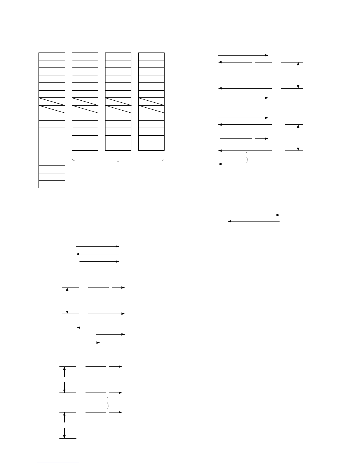
8. Packet Format
F
8 Bits 1Opening flag (8 Bits) (01111110) (7E)
DA
8 Bits 2Destination address (00-FEH)
(SRN Terminal Number)
SA
8 Bits 3Source address (00-FEH)
TYPE
8 Bits 4Packet type (DATA/ACK/RACK/NRDY)
CH NO
8 Bits 5Channel No. (01H = CH1; 02H = CH2)
DLS
8 Bits 6Circuit status: Buffer full, RE-transmit, Unable
7Dummy
BCL
8 Bits 8Number of bytes at the data unit
BCH
8 Bits
DATA
max.
270
bytes.
9DATA
Number of data bytes (270 Bytes)
CRC
8 Bits ΦCRC check code
CRC
8 Bits
F
8 Bits ΓClosing flag (8 Bits) (01111110) (7E)
Fig. 3-3 Packet format
1Opening flag (7E)
The open flag (7E) is sent at the beginning of each packet. As the
SRN control circuit (receiving side) receives the flag, it will start
the receiving operation.
NOTE: The packet begins with the open flag (8 Bits) and ends
with a closing flag (8 Bits).
2Destination address (00H – FEH)
The destination address indicates where the packet is addressed
(receiving unit) too. The terminal number of each unit is converted
into a hexadecimal number to be used for the destination address.
3Source Address (00H – FEH)
The source address indicates the sending unit (transmit unit). The
terminal number of each unit is converted into a hexadecimal
number to be used for the source address.
4Types of packets
There are four types of packets each are used to indicate the type
of packet to be transferred.
00: DATA packet
(summary and preset data)
01: ACK packet
The acknowledging packet that is sent to the transmitting
side from the receiving side to indicate that the packet was
received properly.
02: RACK packet
The acknowledging packet that will be sent to the receiving
side to indicate that the ACK packet has been properly
received by the sending side.
03: NRDY packet
The acknowledge packet that is sent to the sending side to
indicate that it is not ready to receive data.
5Channel No.
Indicates that channel of the packet. (Channel 1 or Channel 2)
6Circuit status
In the case of the NRDY packet, it indicates why the NRDY packet
was issued.
1) Unable to handle received data because the receiving side is
in the BUSY state.
2) Unable to handle received data because the receiving buffer is
full.
7Number of data bytes
Indicates the number of bytes of data, which is a data, packet
status that will be converted into hexadecimal numbers before
transmission. Maximum number of bytes is 270.
8Data
Transfer data is contained in this field. Size of data is limited to a
maximum of 270 bytes. It can only exist in the data packet.
9CRC check code
This check code is used to detect any errors in the transmit data.
A CRC code is generated from the sending side to be sent to the
receiving side.
At the receiving side, the CRC check code is generated on the
basis of the same formula as the sending side to verify it against
the CRC check code receive.
ΦClosing flag (7E)
The closing flag is sent at the end of the packet. When the IRC
control circuit at the receiving side receives the flag, it terminates
the operation.
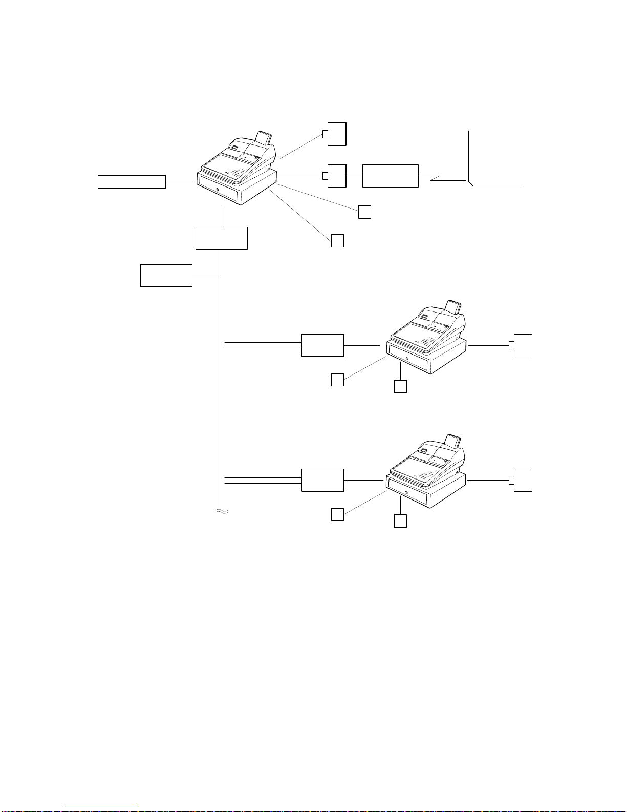
9. Type of packet
Two types of packet formats are available for the SHARP RETAIL
NETWORK. One is the data packet (the content of data is judged by
the host level). The other is the control packet which is responded to
by the controller level and has three types of packets: ACK packet,
RACK packet and NRDY (NOT READY) packet.
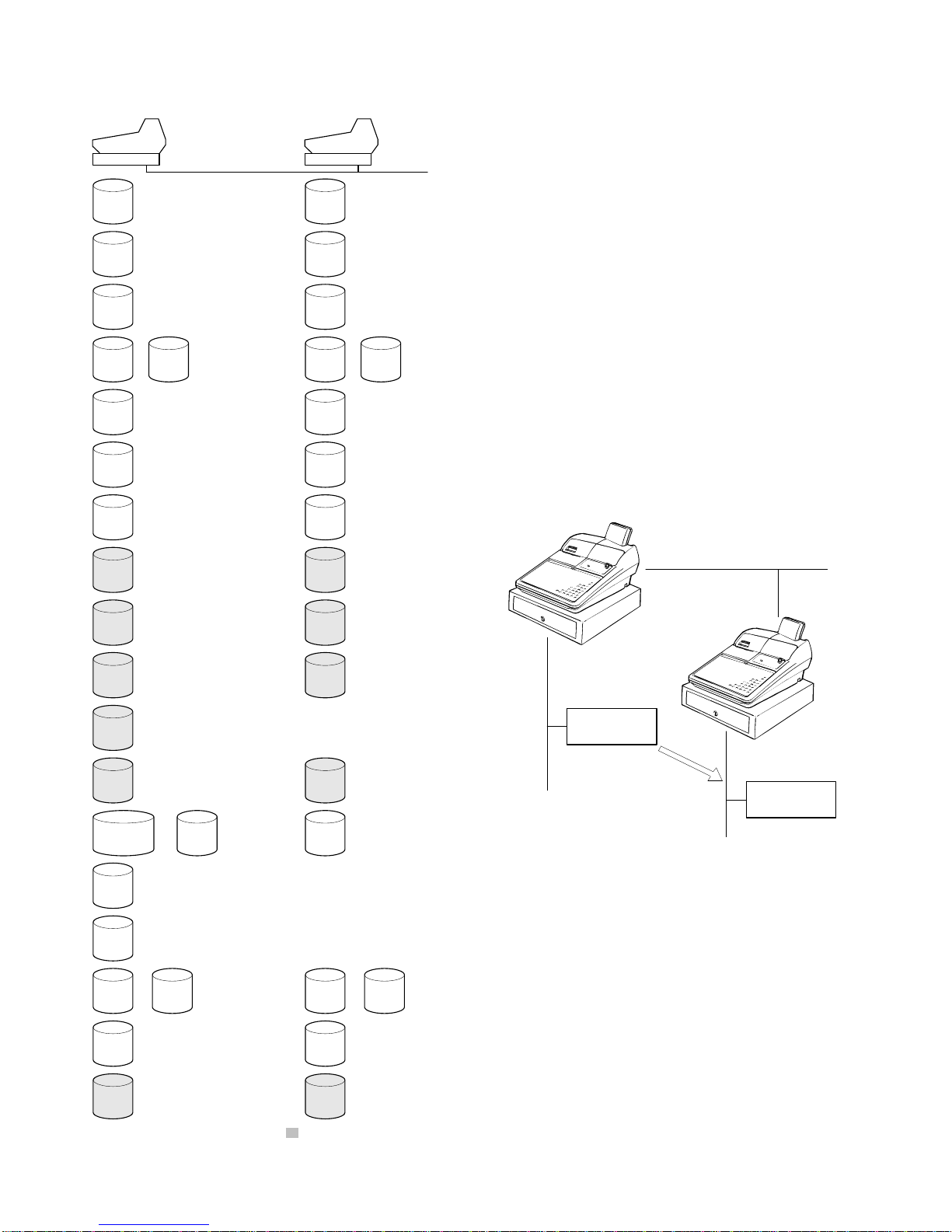
(1) DATA packet: is used for sending and receiving data. Its con-
tents are judged at the host level.
(2) ACK packet: is a response sent from the sink station to the
source station by the link level (of DATA packet) when the DATA
packet is properly received.
(3) NRDY (NOT READY) packet is a response packet of the link
level. It is used in case it is unable to receive in the host level or
no space is available in its receive buffer despite the the error
check CRC of the DATA packet is normal.
1 4