Elmuz DS202A User manual
24-BIT MULTI-BAND COMPRESSOR/LIMITER/X-OVER/DELAYER MODEL DS202A
INSTRUCTION MANUAL
POWER
DS202A
RATIO
CH-SEL
THRESHOLD TIME/PUSH
LOW CU T/N OTCH LOCK
PROGRAM/VOLUME
X-OVER/DELAY
BYPASS
SAVE
RESET MIDI
MULTI-BAND COMPRESSOR/LIMITER/X-OVER/DELAYER
24-BIT DSP/48KHZ SAMPLING RATE
CLIP
3
-
6
-
12
-
18
-
24
-
30
-
36
-
LR
dB
INPUTS
3
-
6
-
12
-
18
-
24
-
30
-
36
-
dB
GAIN REDUCTION
L&R R/SUB.
1
-
CLIP
3
-
6
-
12
-
18
-
24
-
30
-
36
-
dB
OUTPUTS
CLIP
3
-
6
-
12
-
18
-
24
-
30
-
36
-
dB
RSUB.
L
ATTENTION!
All products are carefully packed and designed to protect the units from
rough handling Before shipping out from the factory. Examine your good upon receiving, to ensure no
damage during transportation.Any damage claim should be informed & notified to relative dealer within
14 days of good received. The dealer will not except failing of such. The consignee must make all
shipping claims.
The DS202A fits into a standard 19" rack unit of space (1 3/4"). Allow at least an additional 4" depth
for the connectors on the back panel. Be sure that there is enough air space around the unit for cooling and
ventilation. DO NOT place the DS202A on high temperature devices like power amplifiers to avoid
overheating.
Using a main cable and a standard IEC receptacle makes the main connection of the DS202A. It
meets all of the international safety certification requirements.
Please make sure that all units have a proper ground connection. For your own safety, do not remove
the ground connection within the unit or at the supply, or fail to make this connection at all.
This machine is only intended for qualified personnel to operate & install. Do not attempt to repair
and service yourself but referred to qualified technical service personnel. The user must have sufficient
electrical contact to earth. Electrostatic charges might affect the operation of the DS202A.
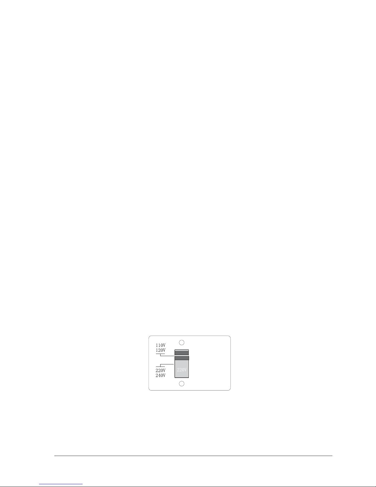
Before switching voltage for local supply requirement, fuse must be installed with correct
type and rate. When the power supply is 220V/240V, fuse is 315mA; and the power supply is 110V/120V,
fuse is changed to 630mA. The switch is preset to 220V/240V in the factory.
NOTICE:
CAUTION
THE POWER
SUPPLY CORD
SHOULD BE
DISCONNECTED
BEFORE
CHANGING
THE VOLTAGE
SELECTOR
Page 1

POWER
DS202A
RATIO
CH-SEL
THRESHOLD TIME/PUSH
LOW CUT /NOTCH LOCK
PROGRAM/VOLUME
X-OVER/DELAY
BYPASS
SAVE
RESET MIDI
MULTI-BAND COMPRESSOR/LIMITER/X-OVER/DELAYER
24-BIT DSP/48KHZ SAMPLING RATE
CLIP
3
-
6
-
12
-
18
-
24
-
30
-
36
-
LR
dB
INPUTS
3
-
6
-
12
-
18
-
24
-
30
-
36
-
dB
GAIN REDUCTION
L&R R/SUB.
1
-
CLIP
3
-
6
-
12
-
18
-
24
-
30
-
36
-
dB
OUTPUTS
CLIP
3
-
6
-
12
-
18
-
24
-
30
-
36
-
dB
RSUB.
L
DS202A
24-bit S-D,A/D,D/A,48kHz sampling rate
Compressor/limiter
3 kinds of output mode
-- 2 inputs, 2 outputs
-- 2 inputs, 2 outputs + sub
-- 2 inputs, 3 outputs
Notch and low cut filter to improve the noise
20 programs. First 3 programs are preset by factory, the other
17 programs can be named, saved and recalled.
MIDI control
2X16 character LCD with backlit
Page 2
POWER
DS202A
RATIO
CH-SEL
THRESHOLD TIME/PUSH
LOW CUT /NOTCH LOCK
PROGRAM/VOLUME
X-OVER/DELAY
BYPASS
SAVE
RESET MIDI
MULTI-BAND COMPRESSOR/LIMITER/X-OVER/DELAYER
24-BIT DSP/48KHZ SAMPLING RATE
CLIP
3
-
6
-
12
-
18
-
24
-
30
-
36
-
LR
dB
INPUTS
3
-
6
-
12
-
18
-
24
-
30
-
36
-
dB
GAIN REDUCTION
L&R R/SUB.
1
-
CLIP
3
-
6
-
12
-
18
-
24
-
30
-
36
-
dB
OUTPUTS
CLIP
3
-
6
-
12
-
18
-
24
-
30
-
36
-
dB
RSUB.
L
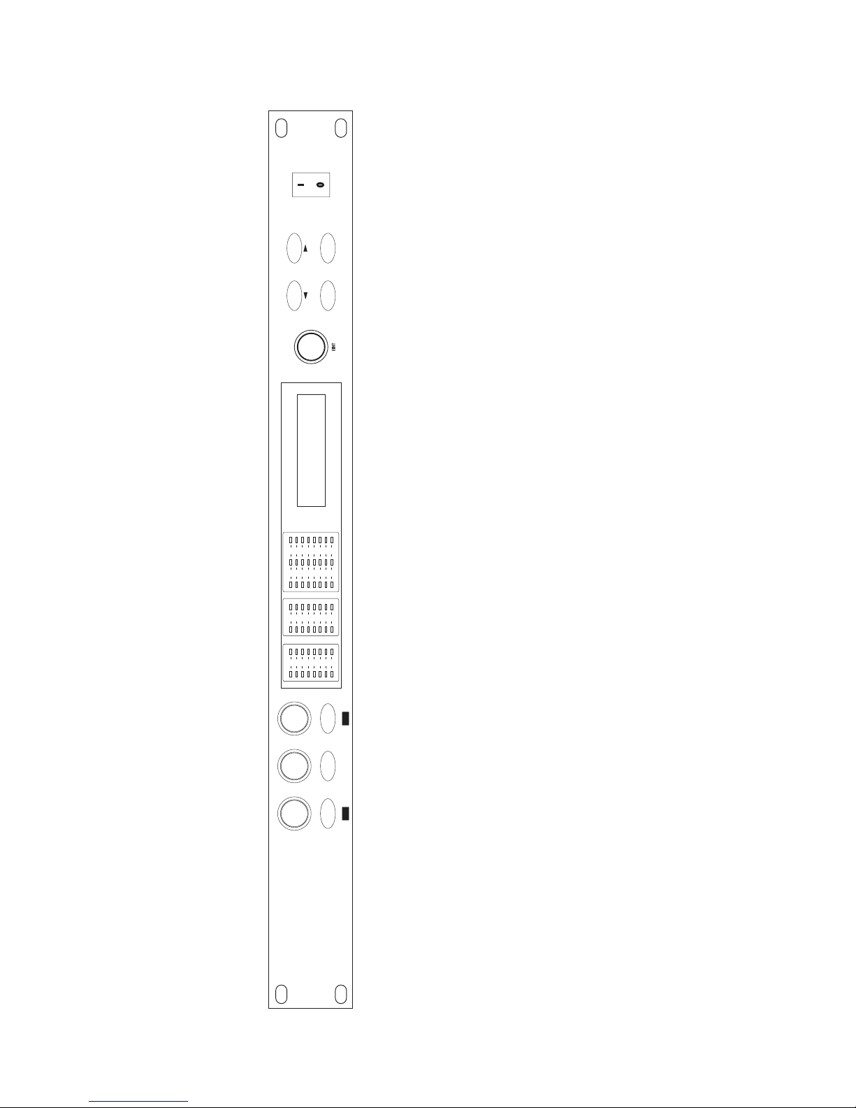
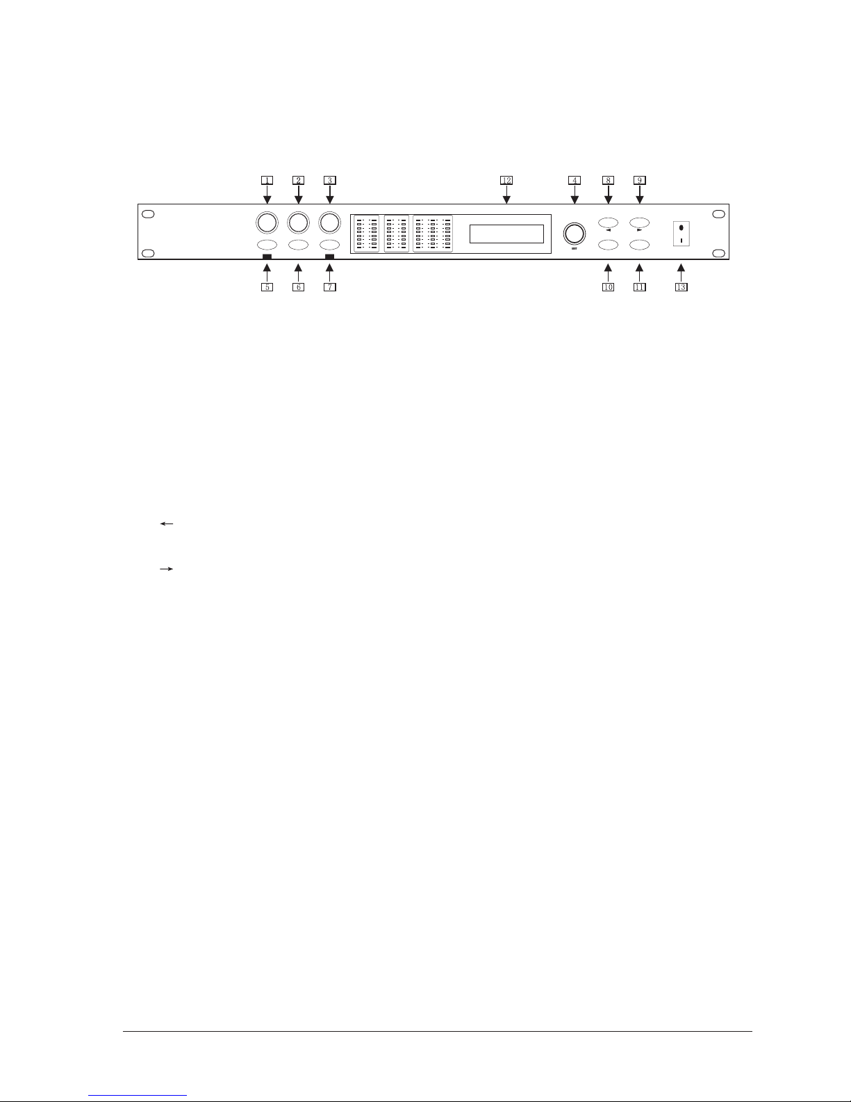
1.RATIO: adjust the compression ratio
2.THRESHOLD: adjust the compression threshold
3.TIME: adjust the constant time and push it to
select different parameters
4.EDIT: turn it to edit the parameters
5.CH-SEL/RESET: select channel/system reset
6.LOW CUT/NOTCH: select low cut function/notch function
7.LOCK/MIDI: function key lock/MIDI function set
8.PROGRAM/VOLUME: select program number/adjust the volume
" ": move the cursor to the left for editing program name
9.BYPASS
" ": move the cursor to the right for editing program name
10.CROSSOVER/DELAY: select crossover/delay menu
11.SAVE: select save function
12.LCD: display all the parameters with character backlit
13.POWER: switch ON/OFF
Page 3
Note:
Under the mode of "Mono Comp+Sub"or "Two Brand Comp" the channel indicates
L&R and "Sub". In this case ,three parameters, Compression ratio, threshold and time,
are adjusted simultaneously for left and right channels.
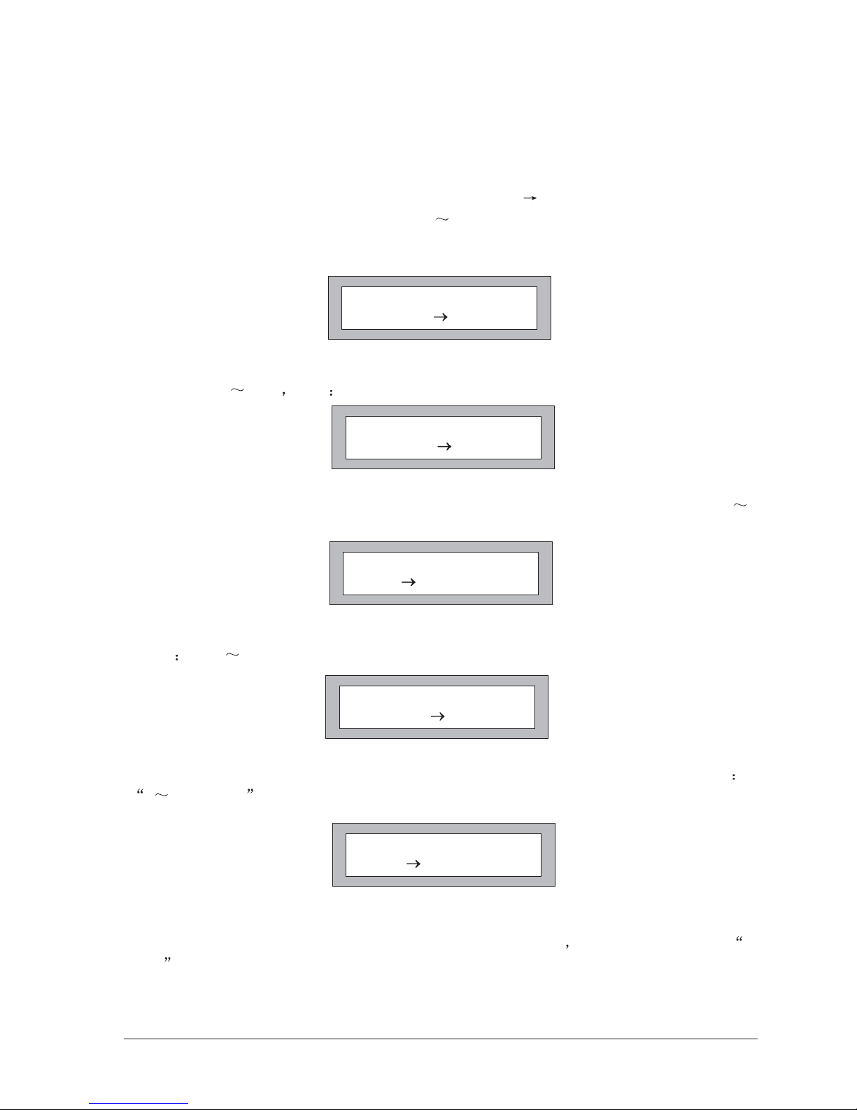
Instruction:
Turn encoder 1 to adjust the compression ratio ,and " " indicates the change of the
value (as fig.1) .The adjustment range:"1.00 Limit".
1.Directly-selected encoders, for example, RATIO,THRESHOLD and TIME encoders,
are adopted for convenient operation.
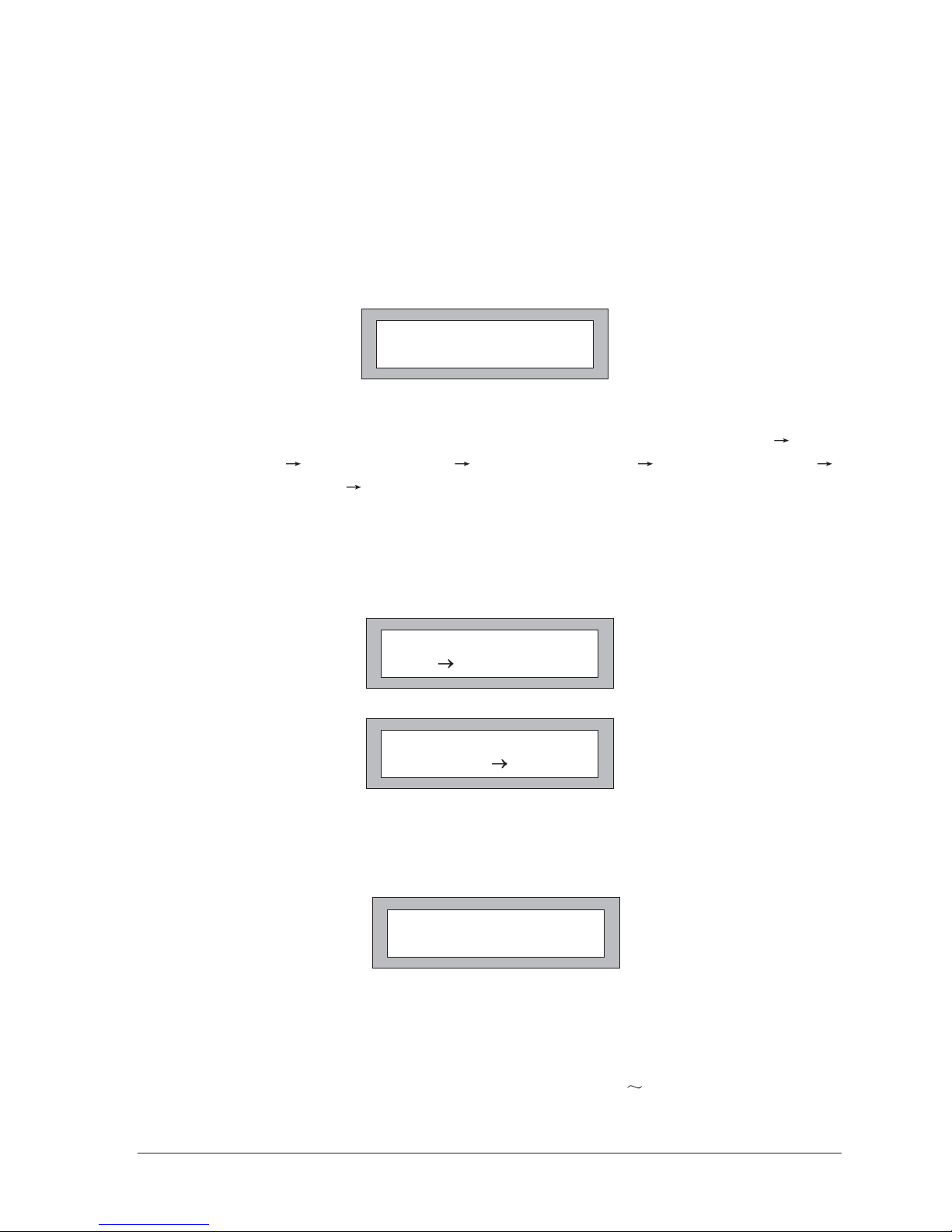
Turn encoder 2 to adjust the compression threshold (as fig.2). The adjustment
range:"-61dB 0dB" step 1dB.
Turn encoder 3 first to adjust attacktime (as fig.3). The adjustment range:"0
350dB/Sec".
And press encoder 3 and turn it to adjust holdtime (as fig.4).The adjustment
range "0ms 100ms".
then
Press encoder 3 again and turn it to adjust decaytime (as fig.5).The adjustment range
0 350dB/Sec .
01 Stereo Comp
Lch Thres. -61dB
Fig.2
01 Stereo Comp
Lch A 350dB/sec
Fig.3
01 Stereo Comp
Lch H time 10ms
Fig.4
01 Stereo Comp
Lch D 350dB/sec
Fig.5
01 Stereo Comp
Lch Ratio 1.00
Fig.1
Page 4
2.CH-SEL-Press it shortly to select the channel to be adjusted ,and the
Corresponding information is showed on the left-bottom of the LCD. Under the mode of
"Stereo Comp","Lch" and "RCH"can be selected; Under the mode of "Mono
Comp+Sub"or "Two Brand Comp", three channels "Lch", "Rch"and "Sub", can be
selected. Press "RESET"button longer and then the system is reset to factory default
settings.
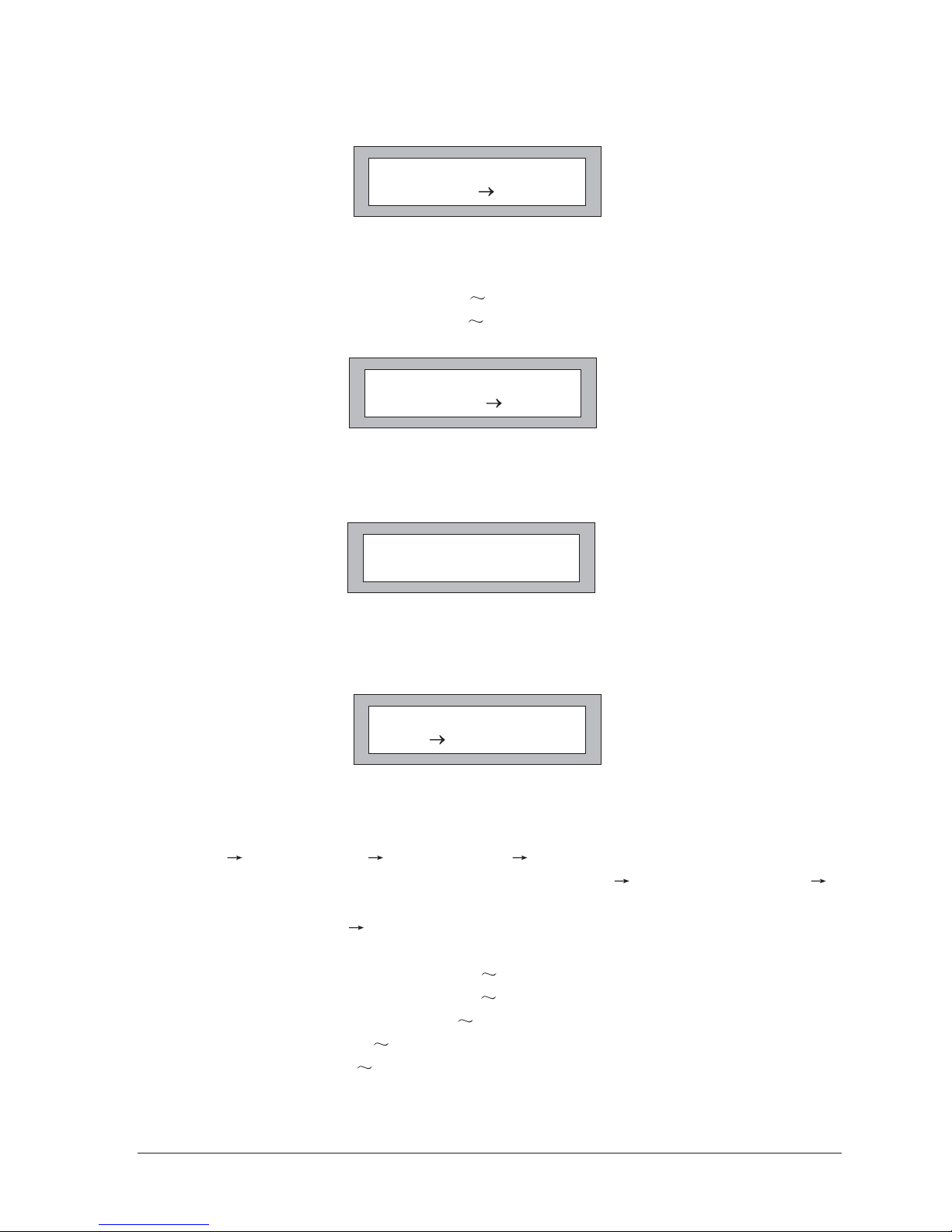
3.LOW CUT/NOTCH-Press it to enter the sub-menu of LOW CUT and NOTCH(as
fig7).In this case ,turn encoder 4 to select one of the following six sub-menus," LOW
CUT SWITCH"," LOW CUT FLT", " NOTCH SWITCH"," LQ NOTCH FLT", "
MQ NOTCH FLT " and " HQ NOTCH FLT". Press the key again and then turn encoder
4 to adjust the value of the corresponding sub-menu(as fig.8).
The adjustment range of LOW CUT:"20Hz-200Hz",step:10Hz;
The adjustment range of NOTCH:"40Hz-110Hz",step:5Hz.
4.LOCK-First press it about 3 seconds to lock all the function buttons and the
information of LOCK is showed in the LCD (as fig.9). Press it again, then all buttons
resume to its original.
5.PROG/VOL -Press it and then turn encoder 4 to select one of 20 different programs
,among which No.1, 2 and 3 programs are preset by factory and can not be changed(as
fig.1);Press it again and then turn encoder 4 to adjust the volume of correspondirg
channel (as fig.10) the adjustment range of the volume:"MUTE +6dB".
01 Stereo Comp
Lch Low cut FLT
Fig.7
01 Stereo Comp
Lch Low cut 20Hz
Fig.8
01 Stereo Comp
LOCK
Fig.9
01 Stereo Comp
SYSTEM RESET
Fig.6
Page 5
Under the mode of "MONO COMP+Sub"or "Two Band Comp", press "
for about two seconds to select the level ratio of the input subwoofer from left and right
Channels.
6.BYPASS-First press it to disable the compression (as fig.12). Press it again to
resume the function.
7.CROSSOVER/DELAY:First press it and then turn encoder 4 to select the sub-menu of
CROSSOVER and DELAY(as fig.13).
Press it again and then turn encoder 4 to edit the value of the corresponding Sub-menu.
The adjustment range of High Pass:"20Hz 250Hz",step:5Hz;
The adjustment range of phase:0,180 .
The adjustment range of"Sub/Left":"OFF 100%",step:10%;
The adjustment range of"Sub/Rch":"OFF 100%",step:10%.
Under the mode of "stereo",only the sub-menus under DELAY can be operated,
including" Millisecond"" Del Meters"" Del Feet"; Under the mode of
"Mono+Sub"or"Two Brand ",the following two sub-menus" High Pass(HPF)"and "
Low Pass(LPF)",are also available to select; Under the mode of "Two Band
Comp",another sub-menu" Phase"is added.
The adjustment range of Delay: "0ms 3.5ms",step:0.05ms;
"0mm 1201mm",step:17mm;
"0ft 3.945ft",step:0.057ft;
O
PROG/VOL"
The adjustment range of Low Pass: "20Hz 250Hz",step:5Hz;
01 Stereo Comp
Lch Volume -30dB
Fig.10
02 Mono Comp+Sub
L&R Sub/Left 100%
Fig.11
01 Stereo Comp
BYPASS
Fig.12
01 Stereo Comp
Lch Millisecond
Fig.13
Page 6

Note:
In the case of Mono and Crossover compression, the crossover frequency of the High
Pass and the Low Pass is adjusted simultaneously in order to ensure the frequency
response.
8.SAVE-First press it to enter the editable stage. As the first 3 programs have been
preset by factory and can not to be edited again, the editable programs for the user can
only start from No.04 (as fig.14).The max sequence number:20
Press" "or" "button to move the cursor to the correct position and then turn encoder
4 to select the correct editable symbol. Press it again(as fig.15),and the information of
"SAVE NOW" disappears after about three seconds, which shows that the function is
finished.
04
Lch Ratio 1.00:
Fig.14
04 ABCDEFGH
SAVE NOW...
Fig.15
Page 7

1. MAIN CONNECTOR/FUSE HOLDER/VOLTAGE SELECTOR: Before you
connect the unit, please make sure that the displayed voltage corresponds to your Mains supply.
Please note that the AC voltage selection is defined by the position of the Fuse Holder. If you
intend to change the two markers monitors the selected voltage, Please note that, depending on
the mains voltage supplied to the unit, the correct fuse type and rate must be installed (see
Technical Specifications). Please use the enclosed main cable to connect the unit to the mains
power supply.
XLR or TRS output socket, Parallel between XLR & TRS input.
Balanced & Unbalanced configuration.
XLR or TRS input socket, Parallel between XLR & TRS input.
Balanced & Unbalanced Configuration
adjust the unit to different level from -20dB to +4dB
110/120V or 220/240V
2. ANALOG OUTPUT:
3. ANALOG INPUT:
4. INPUT LEVEL
5. MIC OUTPUT SOCKET
6. MIC INPUT SOCKET
7. SUBWOOFER OUTPUT
8. MIDI INPUT
9. VOLTAGE SWITCH:
SUBWOOFER OUTPUTS
INPUT LEVEL INPUT LEVEL
OUTPUTS 1INPUTS 2 INPUTS 1
SERIAL NUMBER
DATE CODE
OUTPUTS 2
REAR PANEL
Page 8

TECHNICAL SPECIFICATIONS
Analog Inputs
Connectors XLR and 1/4" jack
Type RF filtered, servo balanced , 20kOhms unbalanced
Impedance 40kOhms balanced, 20kOhms unbalanced
Nominal Operating Level -20dB to +4dB
Analog Outputs
Connectors XLR and 1/4" jack
Type Electronically servo-balanced output stage
Impedance 66kOhms balanced, 33kOhms unbalanced
System specifications
Frequency Response 20Hz 20KHz 1dB
Dynamic Range >112dB,20Hz 20KHz
S/N >115dB
THD <0.065%,@1KHz,0dB
Compression
Threshold -61dB 0dB,1dB step
Ratio 1.0 Limit
Detect Time 0 350dB/Sec
Attack Time 0 100ms
Decay Time 0 350dB/Sec
MIDI Interface
Type 5-Pin-DIN-Socket
Digital Processing
Converters 24-bit Sigma-Delta
Sampling Rate 48KHz
2 16 LCD display
Mains supply General Export Model 110-120V,200-240V, 50-60Hz
Fuse 110-120VAC: 250mA(slow-blow)
200-240VAC: 125mA(slow-blow)
Power consumption 10W
Mains connection Standard IEC receptacle
Dimension 45 482 152(mm)
Gross weight 3 kg
Display
Powersupply
Physical
Page 9
Table of contents
Other Elmuz Recording Equipment manuals


