Sharpe 310596G Parts list manual
Instructions/Parts
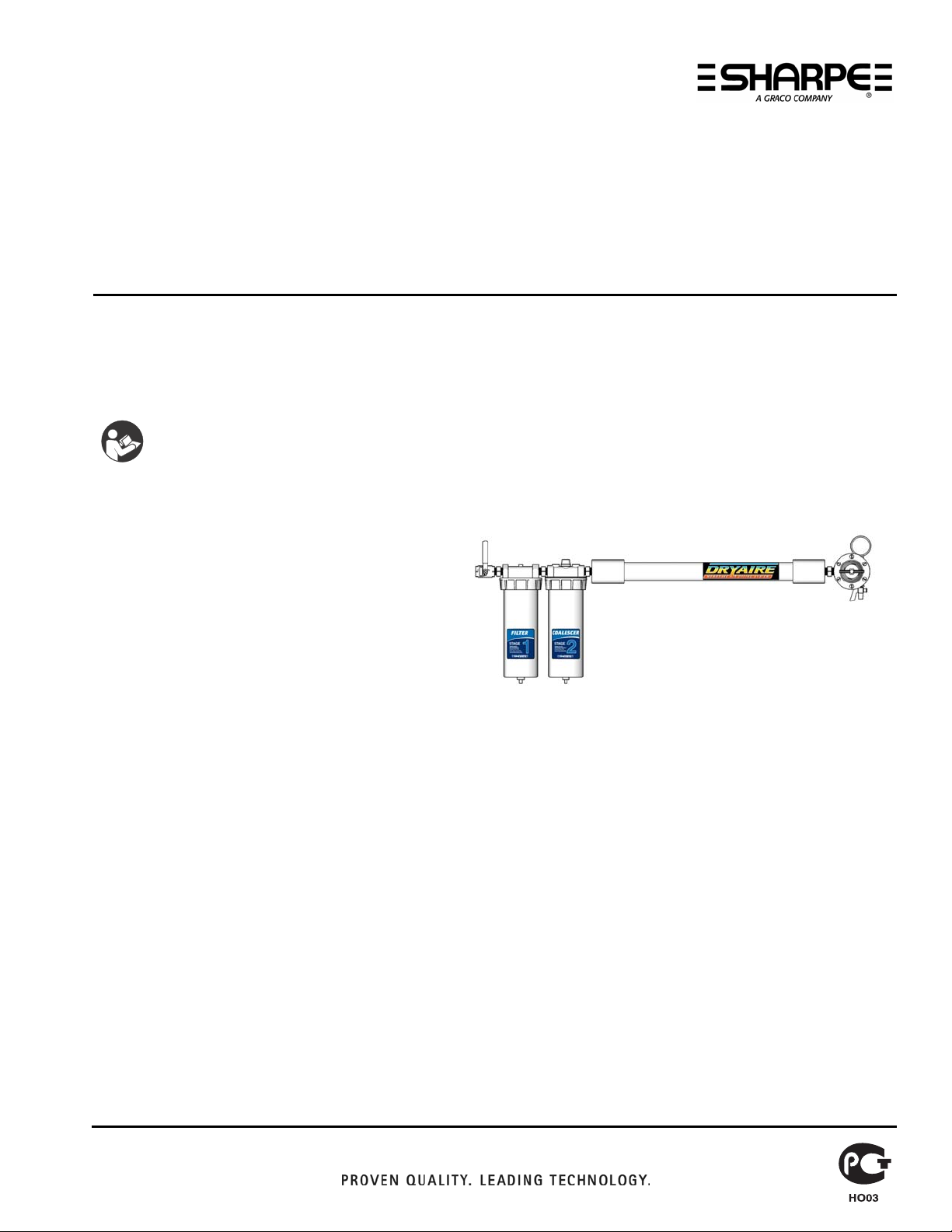
Dryaire Membrane
Air Drying System 310596G
ENG
Model 6770
Maximum Working Pressure: 175 psi (1.2 MPa, 12 bar)
System Includes:
•Air Filter w/Overnight Drain (Part No. 22601)
•Coalescer w/Overnight Drain (Part No. 22605)
•Air Regulator Assembly (Part No. 22604)
•Membrane Air Dryer (Part No. 1-6770-3)
System Description
Sharpe’s DRYAIRE Membrane Air Drying System
is the painter’s insurance for removing dirt, water, oil, and uncondensed moisture from compressed air lines. It
provides clean dry compressed air while reducing overall costs and minimizing waste.
Sharpe’s 3-Stage Point-of-Use System comes assembled and is simple to install.
Approved for Paint Company warranty programs when applying today’s state-of-the-art refinish materials.
Ideal for protecting moisture sensitive tools.
Advanced Membrane Technology
•Point-of-Use air dryer
•Optimize overall drying costs
•Effective even at low flow rates
•No chemicals to dispose of
•Transparent operation
•Continuous, effective air drying
•No maintenance on Stage 3
•No electricity
•No additional hookups or connections
•Easy installation
Important Safety Instructions
Read all warnings and instructions in this
manual. Save these instructions.
Model 6770 Membrane Air Drying System

DRYAIRE MEMBRANE AIR DRYING SYSTEM
2
Specifications
STAGE 1: Air Filter w/Overnight Drain (Part No. 22601)
Provides removal of water and contaminants down to 5 microns.
Air Inlet 1/2 in. F.P.T.
Air Outlet 1/2 in. F.P.T.
Air Flow Capacity 115 cfm (3.2 m3/min.)
Max. Operating Pressure 175 psi (1.2 MPa, 12 bar)
Max. Temperature 150°F (65°C)
STAGE 2: Coalescer w/Overnight Drain (Part No. 22605)
Provides removal of oil and sub-micronic particles down to .01 microns.
Air Inlet 1/2 in. F.P.T.
Air Outlet 1/2 in. F.P.T.
Air Flow Capacity 70 cfm (2.0 m3/min.)
Max. Operating Pressure 175 psi (1.2 MPa, 12 bar)
Max. Temperature 150°F (65°C)
STAGE 3: Membrane Air Dryer (Part No. 1-6770-3)
Provides removal of uncondensed moisture.
Air Inlet 1/2 in. F.P.T.
Air Outlet 1/2 in. F.P.T.
Air Flow Capacity 30 cfm (0.85m3/min.)
Max. Operating Pressure 175 psi (1.2 MPa, 12 bar)
Max. Temperature 175°F (79°C)
Warning
Installation
1. Install Air Drying System as close as possible to the point where the air is being used.
2. Install main shut-off valve (part no. 22695) upstream of air system to allow maintenance of the unit.
3. Install system with air flow through filters in the direction noted on top of units.
4. Minimum 1/2 in. npt piping is recommended. Avoid using many fittings, couplings, etc. that restrict air flow.
5. Maximum operating pressure and operating temperature of system is: 160 psi (1.1 MPa, 11 bar) and 150°F (65°C).
Relieve the pressure when you stop spraying and
before cleaning, checking, or servicing equipment.

DRYAIRE MEMBRANE AIR DRYING SYSTEM
3
Operation
After the system is installed and ready to use:
1. Attach air hose(s) to outlet valve (part no. 34700).
2. Open main shut-off valve upstream of system.
3. Adjust regulator to desired setting by turning T-handle adjusting screw in or out.
4. Open outlet valve (part no. 34700) to supply air to spray guns or tool being used.
5. With air flowing, readjust air pressure at regulator if necessary.
6. Be sure to turn off unit when not in use.
Maintenance
1. Check system at least once per shift to ensure proper drainage.
2. Before performing maintenance on system, close main shut-off valve located upstream. Bleed off residual air in
system.
New Membrane Technology
wet air enters
membrane module
water vapor purges clean, dry air exits
module
water vapor permeates through
hollow membrane fibers
SHUT-OFF VALVE
(22695)
FILTER
(22601)
COALESCER
(22605)
MEMBRANE
AIR DRYER
(1-6770-3)
AIR REGULATOR
(22604)
OUTLET VALVE
(34700)

DRYAIRE MEMBRANE AIR DRYING SYSTEM
4
Air Filter w/Overnight Drain (Part
No. 22601)
Maintenance
To maintain maximum filtering efficiency and to avoid
excessive pressure drop, the filter must be kept clean.
Bowl drainage is automatic with the overnight drain;
however, manual draining can also be done by removing
the bowl. A visible coating of dirt on the filter element
surface or an excessive pressure drop is an indication
that cleaning is necessary.
Cleaning
To clean, it is not necessary to remove the complete filter
from the line. Disassembly is simple and does not require
tools. Before disassembly, shut off the air supply and
depressurize filter. Clean all parts with cleaning solvent
and blow out filter body before reassembly. Wash filter
element in cleaning solvent and blow out from the inside.
Overnight Drain
The overnight drain (part no. 22631) is simple in design
and operation. When the filter bowl is pressurized, the
piston travels down against the spring and closes the
drain opening. When the bowl is depressurized (i.e.:
overnight when system is shut down), the spring lifts the
piston from the seal allowing the bowl to drain.
NOTE: The overnight drain can be operated manually at
anytime by pushing the piston stem up.
Parts
22638
22645
22640
22631
push to
manually drain
(open)
Part No. Description
22631 Overnight Drain
22632 Mounting Bracket
22638 O-Ring
22640 Baffle Kit
22645 Filter Element

DRYAIRE MEMBRANE AIR DRYING SYSTEM
5
Coalescer w/Overnight Drain
(Part No. 22605)
Installation
It is always recommended that a SHARPE air filter be
installed upstream of the coalescing filter to remove 5
micron and larger size particles and separate large
droplets of moisture from the air line.
Maintenance
Never let the liquid level in the bowl reach the base of the
coalescing element.
Cleaning
To clean, it is not necessary to remove the complete filter
from the line. Disassembly is simple and does not
require tools. Before disassembly, shut off the air supply
and depressurize coalescer. Clean all parts with
cleaning solvent and blow out body before reassembly.
Replace coalescing element (part no. U23075).
Pressure Drop Indicator
The differential pressure drop indicator on this unit is
designed to provide early detection of a clogged
coalescing filter element. As the filter element becomes
clogged the red indicator will start to rise while air is
flowing through the unit. When the pressure drop across
the element reaches 10-12 psi (0.07-0.08 MPa, 0.7-0.8
bar) the red indicator will be in full view and the element
should be replaced. Failure to replace the element when
the pressure drop exceeds 10 psi (0.07 MPa, 0.7 bar)
will affect your air quality and tool efficiency.
Overnight Drain
The overnight drain (part no. 22631) is simple in design
and operation. When the filter bowl is pressurized, the
piston travels down against the spring and closes the
drain opening. When the bowl is depressurized (i.e.
overnight when system is shut down), the spring lifts the
piston from the seal allowing the bowl to drain.
NOTE: The overnight drain can be operated manually at
anytime by pushing the piston stem up.
Parts
Part No. Description
22631 Overnight Drain
22632 Mounting Bracket
22647 O-Ring
22650 Pop-up Indicator Repair Kit
U23075 Coalescer Element
22650
22647
U23075
22631
push to
manually drain
(open)
DRYAIRE MEMBRANE AIR DRYING SYSTEM
6
I
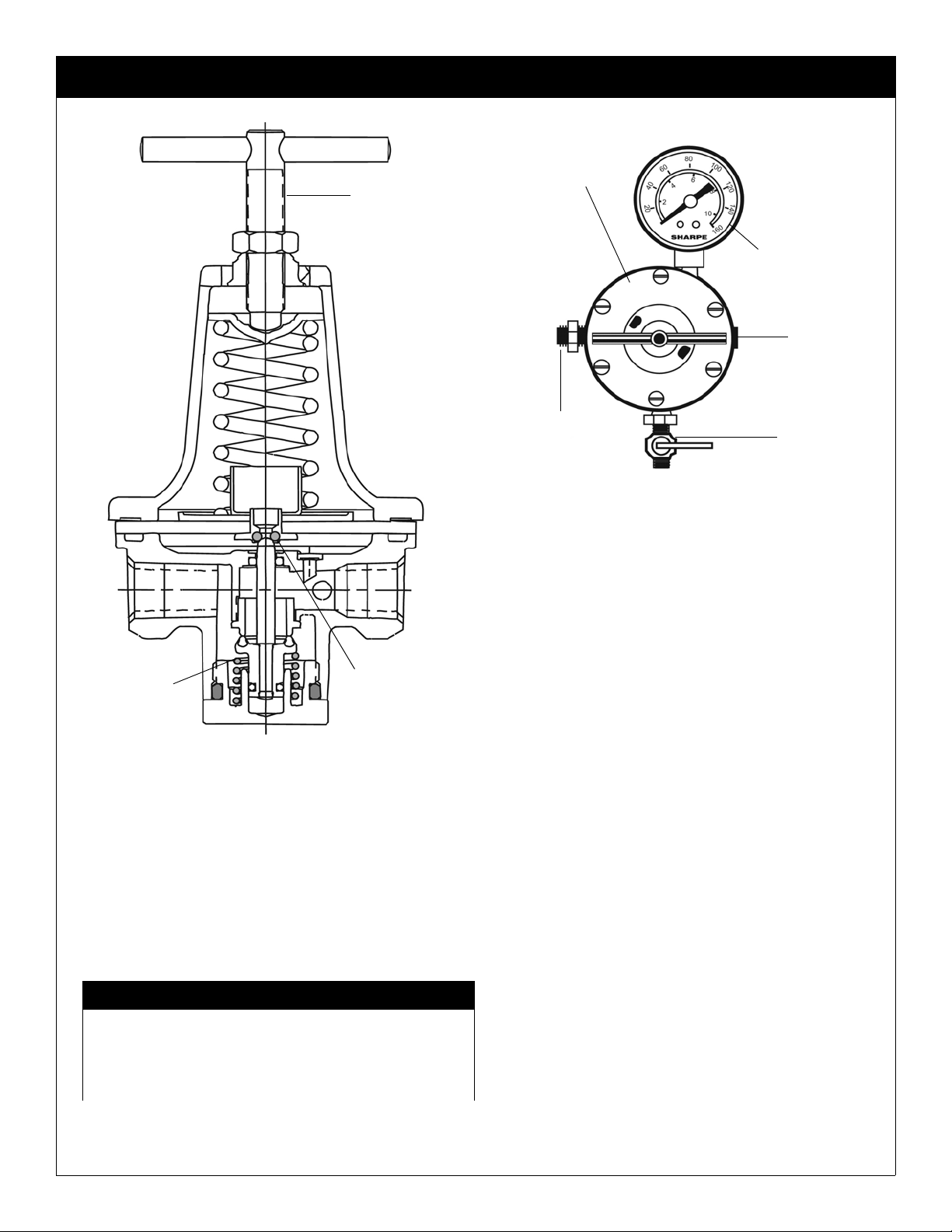
S e l f - R e l i e v i n g A i r R e g u l a t o r
(Part No. 22604)
Maintenance
If the air supply is kept clean, this regulator will provide
long periods of uninterrupted service. Erratic regulator
operation or loss of regulation is most always due to dirt
in the diaphragm area and cleaning is in order.
Cleaning
Depressurize regulator, remove bottom plug, spring
valve, and diaphragm. Clean parts with denatured
alcohol, wipe off seat and blow out body with
compressed air. Reassemble parts as a unit and screw
into regulator before tightening bottom plug Make sure
disc is in center hole in body. Should regulator continue
to malfunction, obtain diaphragm/valve repair kit (part
no. 22680) and replace parts provided.
22682
22680
22685
Specifications
Air Inlet 3/8 in. F.P.T.
Air Outlet 1/4 in. F.P.T. (3 EA.)
Air Flow Capacity 100 cfm (2.8 m3/min.)
Max. Operating Pressure 160 psi (1.1 MPa, 11 bar)
Max. Temperature 150°F (65°C)
Parts
Part No. Description
8230 Air Pressure Gauge
10028 Plug
22680 Diaphragm/Valve Repair Kit
22682 T-Handle Adjusting Screw
22685 Bottom Spring
AIR REGULATOR
(22604)
AIR PRESSURE
GAUGE (8230)
NIPPLE
(22687)
PLUG
(10028)
OUTLET
VALVE
(34700)
DRYAIRE MEMBRANE AIR DRYING SYSTEM
7
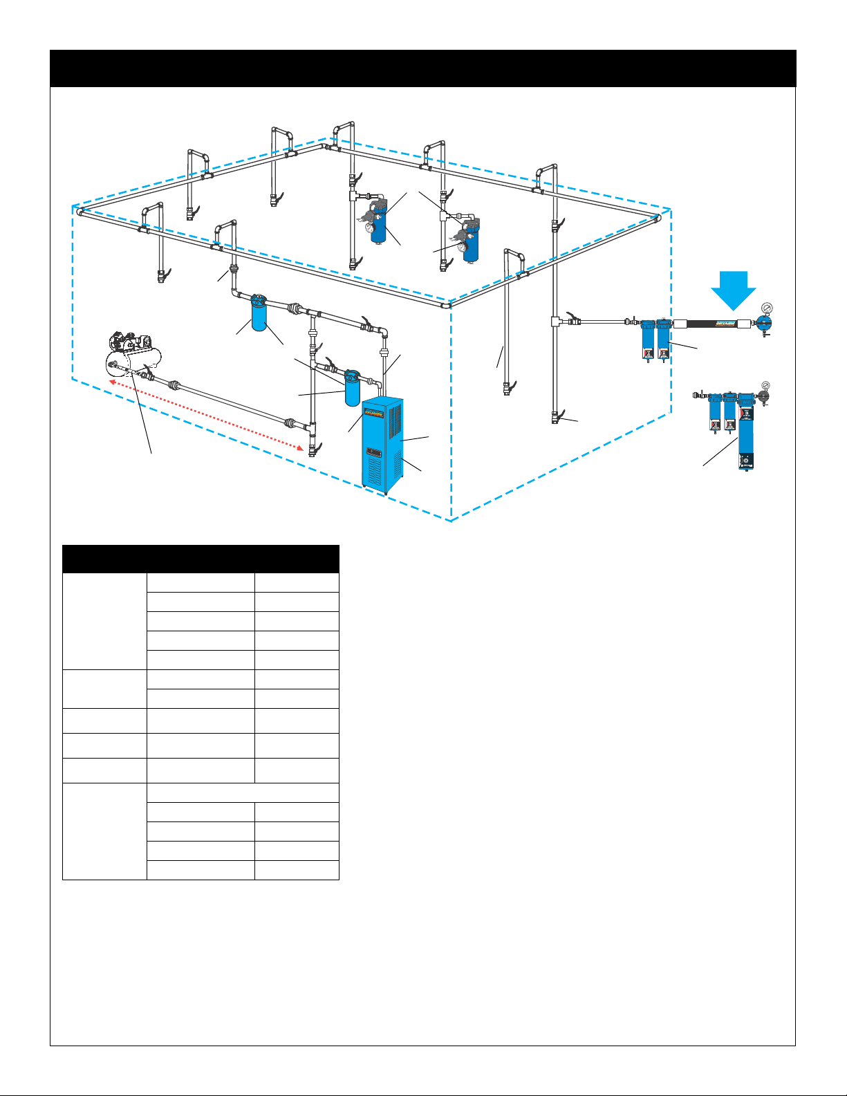
Ref. Letter Description Model No.
ASharpe 606 U06710
Sharpe 606A U06720
Sharpe 606B 6730
Sharpe 880A 6950
Sharpe F88 8130
B707C 6930
707F 6920
707FC 6910
CDryaire Membrane 6770
DDryaire Desiccant 6760
ERefrigerated Air Dryer
25CFM 6880
35CFM 6885
50CFM 6890
75CFM 6895
3!452!
4%$
./2-!
$%3)##!.4
Air Control Unit
or Air Filter
Refrigerated
Air Dryer
Dryaire Membrane
or Desiccant Air
Drying Systems at
Compressor
Model 707C
Oil Coalescer
Model 707F
Air Filter
Drain Leg
Ball Valve
Union
Air In
Air Out
Flexible Hose Between com-
pressor and Main Air Line
15ft.to20ft.
Main Air Line 1 in.
A
C
D
E
B

All written and visual data contained in this document reflects the latest product information available at the time of publication.
Graco reserves the right to make changes at any time without notice.
Original instructions. This manual contains English. MM 310596
SHARPE MANUFACTURING • P.O. BOX 1441, MINNEAPOLIS, MN 55440-1441
1-800-742-7731, www.sharpe1.com
Copyright 2006, Graco Inc. is registered to ISO 9001
Revised 02/2011
DRYAIRE MEMBRANE AIR DRYING SYSTEM
1 Year Limited Warranty
Sharpe warrants this product to the original user against defective material or workmanship for a period of 1 year from the
date of purchase.
Sharpe reserves the right to determine whether the part or parts failed because of defective material, workmanship, or
other causes. Failures caused by accident, alteration, or misuse are not covered by this warranty.
Sharpe, at its discretion, will repair or replace products covered under this warranty free of charge. Repairs or replacements
of products covered under this warranty are warranted for the remainder of the original warranty period.
Sharpe or its authorized service representatives must perform all warranty repairs. Any repair to the product by unauthor-
ized service representatives voids this warranty. The rights under this warranty are limited to the original user and may not
be transferred to subsequent owners.
This warranty is in lieu of all other warranties, expressed or implied, including warranties of merchantability and fitness for a
particular purpose. Some states do not allow the exclusion or limitations of incidental or consequential damages, so the
above limitations may not apply to you.
Sharpe Information
TO PLACE AN ORDER, contact your SHARPE distributor or call 1-800-742-7731 or visit our website at www.sharpe1.com.
Product Registration
Thank you for the purchase of your Sharpe®product. We greatly appreciate your business.
Important reasons to register your product:
•Registration enables Sharpe to notify you if there is a problem with your product.
•Improved Product Development - Your input helps us continue to design products that meet your needs.
For the most up-to-date information and to register your product, please go to www.sharpe1.com and click on “Register
Product.”
Table of contents
Other Sharpe Dehumidifier manuals


