Sharpe 6880 Parts list manual
Instructions/Parts
Dryaire Refrigerated
Air Dryers 310884D
ENG
To remove humidity from compressed air supply.
Models 6880, 6885, 6890, and 6895
Contents
General Safety Information . . . . . . . . . . . . . . . . . . . 2
Installation . . . . . . . . . . . . . . . . . . . . . . . . . . . . . . . . 2
Operation . . . . . . . . . . . . . . . . . . . . . . . . . . . . . . . . . 4
Maintenance . . . . . . . . . . . . . . . . . . . . . . . . . . . . . . . 5
Troubleshooting . . . . . . . . . . . . . . . . . . . . . . . . . . . . 7
Specifications . . . . . . . . . . . . . . . . . . . . . . . . . . . . . . 9
Electrical Schematics . . . . . . . . . . . . . . . . . . . . . . 10
Dimensions and Weights . . . . . . . . . . . . . . . . . . . . 12
Parts List . . . . . . . . . . . . . . . . . . . . . . . . . . . . . . . . . 14
Warranty . . . . . . . . . . . . . . . . . . . . . . . . . . . . . . . . . 16
Important Safety Instructions
Read all warnings and instructions in this manual.
Save these instructions.
Instructions/Parts
2General Safety Information
General Safety Information
Installation
Location
Air Compressor Intake
Locate air compressor so that contaminants potentially
harmful to the dryer are not drawn into the air system.
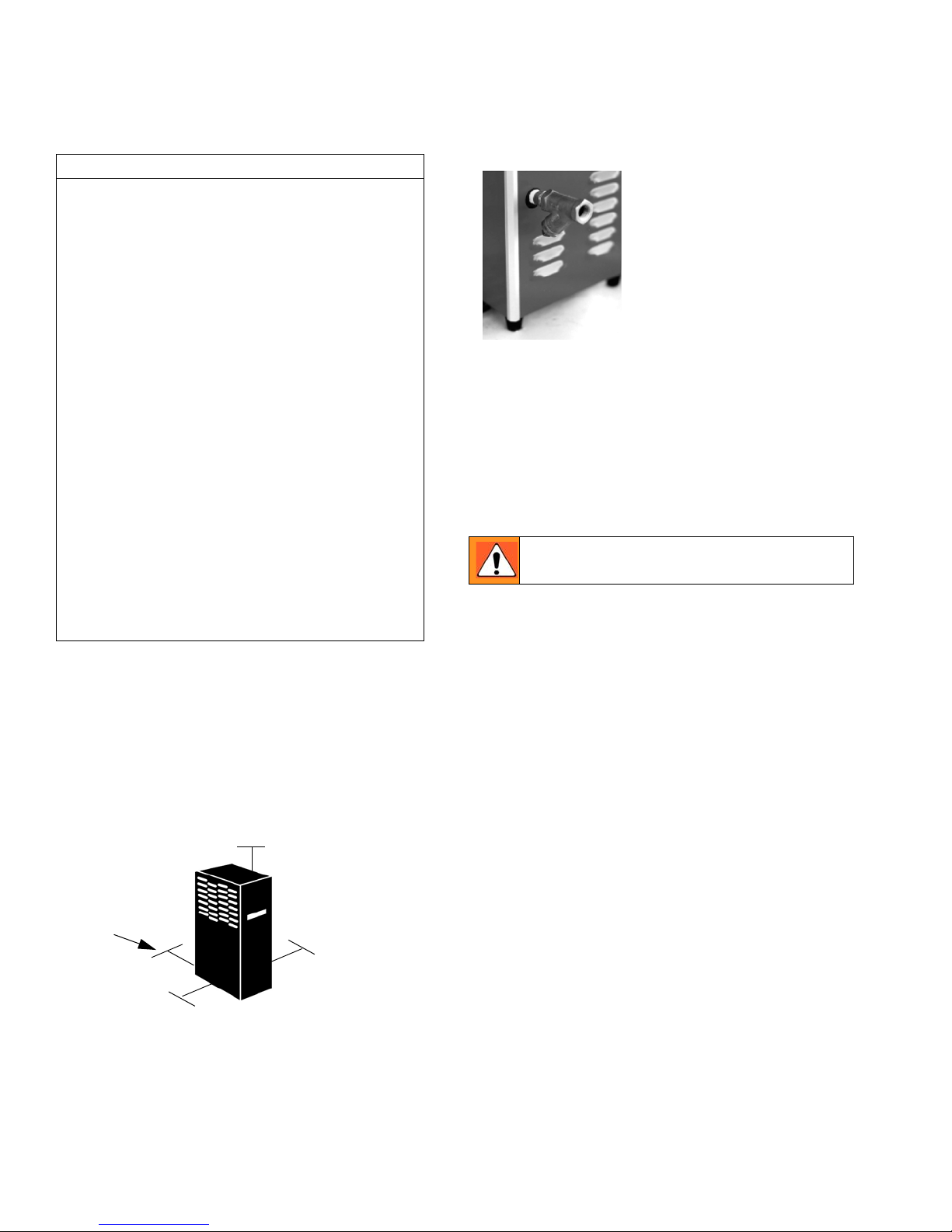
Free Air Flow
Do not block either side of the cabinet. Observe mini-
mum installation clearances as shown below.
Mounting
Dryer is suitable for floor or shelf mounting.
Piping connections
Air Inlet
Connect compressed air
line from air compressor to
air inlet using strainer sup-
plied.
Install strainer (included in
shipping carton) prior to
dryer inlet using pipe nipple
supplied or other piping as
required.
NOTE:
•Observe flow direction arrows on strainer.
•Install strainer where it is easily accessible for clean-
ing.
•Use vibration dampener if vibration exists in air line
at inlet to dryer.
For maximum capacity, install unit in air system at high-
est pressure possible (for example, before pressure
reducing valves).
For maximum capacity, install unit at coolest com-
pressed air temperature possible. Maximum inlet com-
pressed air temperature is 180°F (82°C). If inlet air
exceeds this temperature, precool the air by extending
the piping between the compressor and the dryer.
Air Outlet
Connect air outlet to downstream air lines.
Bypass Piping
If servicing the unit without interrupting the air supply is
desired, piping should include inlet and outlet isolation
valves and an air bypass valve.
Condensate Drain
It is advisable to connect drain outlet to the condensate
drainage system.
NOTE: Drain discharge is at system pressure. Drain line
should be anchored to prevent whipping.
CAUTION
Pressurized Devices
This equipment is a pressure containing device.
•Do not exceed maximum operating pressure as
shown on equipment serial number tag.
•Make certain equipment is depressurized before
servicing.
Electrical
This equipment requires electricity to operate.
•Install equipment in compliance with national and
local electrical codes.
•Standard equipment is supplied with NEMA 1
electrical enclosures and is not intended for
installation in hazardous environments.
•Disconnect power supply to equipment when
performing any electrical service work.
Breathing Air
•Air treated by this equipment may not be suitable
for breathing without further purification. Refer to
OSHA standard 1910.134 for the requirements
for breathing quality air.
36 in.
6 in.
24 in.
12 in.
Wall
Do not exceed the unit’s maximum working
pressure -- 175 psig (12.3 kgf/cm2).
Instructions/Parts
Installation 3
Electrical connections
Dryer is designed to operate on power supply (voltage)
listed on serial number tag located on the back of the
dryer.
Dryer is supplied with an electrical cord.
Install in receptacle of proper voltage.
NOTE: Models 6890 and 6895 (115V only)
Install plug in receptacle rated for 20 amps.
Units are supplied with 20 amp plug.
NOTE: Refrigeration system is designed to run continu-
ously and should NOT be wired to cycle on/off with the
air compressor.
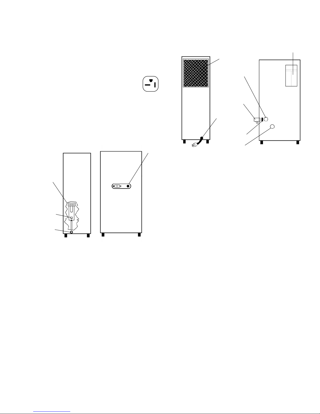
Plug
Front
Left Side
Control
Panel
Separator
and
Integral
Filter
Drain
Connection
Drain
Mechanism
Serial
Tag
Number
Right Side Back
Ambient Air
Filter
Pipe
Nipple
Air Outlet
Connection
Electrical
Connection
Air Inlet
Connection
Strainer
(shipped
separately)

Instructions/Parts
4Operation
Operation
NOTE: Installations above 6000 ft (1825 m)
Unit is adjusted to operate in altitudes up to 6000 ft
(1825 m). If unit is installed in an altitude above this, and
has not been preset at the factory for this altitude, con-
tact Manufacturer’s Service Department.
Start-up
Start refrigeration system by pushing on/off switch to the
ON position (depress rocker switch on side marked “I”).
NOTE: The fault light may illuminate when unit is ener-
gized. Light should go out approximately 5 min. after
start-up. If light remains lit after 30 min. or illuminates
after going out, see Troubleshooting page 7.
Operating Checkpoints
Check the following on a periodic basis:
•Rocker switch is in the ON position.
•Amber fault light is out.
•Condensate is being regularly discharged.
Minimum/Maximum Operating Conditions
•Minimum/Maximum air pressure: 20/175 psig (1.4/
12.3 kgf/cm2)
•Maximum inlet air temperature: 180°F (82°C)
•Minimum/Maximum ambient temperature: 35/110°F
(2/43°C)
•Maximum flow capacity:
For dryers without an aftercooler installed upstream
Flow capacity in scfm (m3/min) @ 180°F (82°C) inlet
temperature, 160°F (71°C) inlet pressure dew point,
95°F (35°C) ambient temperature, 50°F (10°C) outlet
pressure dew point, and less than 5 psi (0.35 kgf/cm2)
pressure drop.
60 Hz
50 Hz
For dryers with an aftercooler installed upstream
Flow capacity in scfm (m3/min) @ 100°F (38°C) inlet
temperature, 100°F(38°C) inlet pressure dew point,
100°F (38°C) ambient temperature, 50°F (10°C) outlet
pressure dew point, and less than 10 psi (0.7 kgf/cm2)
pressure drop.
60 Hz
50 Hz
On/Off Switch Fault Light
Control Panel
Inlet Pressure
psig (kgf/cm2) 175 (12.3) 150 (10.6)
125
(8.8)
100
(7.0)
Model
6880 29 (0.82) 27 (0.76) 25 (0.71) 23 (0.65)
6885 41 (1.16) 38 (1.08) 35 (0.99) 32 (0.91)
6890 58 (1.64) 54 (1.53) 50 (1.42) 45 (1.27)
6895 87 (2.46) 81 (2.29) 75 (2.12) 68 (1.93)
Inlet Pressure
psig (kgf/cm2) 175 (12.3) 150 (10.6)
125
(8.8)
100
(7.0)
Model
6880 24 (0.68) 23 (0.65) 21 (0.59) 19 (0.54)
6885 31 (0.88) 29 (0.82) 27 (0.76) 24 (0.68)
6890 58 (1.64) 54 (1.53) 50 (1.42) 45 (1.27)
6895 71 (2.01) 66 (1.87) 61 (1.73) 55 (1.56)
Inlet Pressure
psig (kgf/cm2) 175 (12.3) 150 (10.6)
125
(8.8)
100
(7.0)
Model
6880 40 (1.13) 37 (1.05) 34 (0.96) 31 (0.88)
6885 55 (1.56) 51 (1.44) 47 (1.33) 43 (1.22)
6890 78 (2.21) 73 (2.07) 67 (1.90) 61 (1.73)
6895 118 (3.34) 110 (3.12) 102 (2.89) 92 (2.61)
Inlet Pressure
psig (kgf/cm2) 175 (12.3) 150 (10.6)
125
(8.8)
100
(7.0)
Model
6880 33 (0.93) 31 (0.88) 29 (0.82) 26 (0.74)
6885 43 (1.22) 40 (1.13) 37 (1.05) 33 (0.93)
6890 78 (2.21) 73 (2.07) 67 (1.90) 61 (1.73)
6895 96 (2.72) 90 (2.55) 83 (2.35) 75 (2.12)

Instructions/Parts
Maintenance 5
Maintenance
Ambient Air Filter
Clean accumulated dust and dirt from ambient air filter
monthly or more often if air flow across the condenser is
impeded.
1. Remove top panel.
2. Remove ambient air filter by sliding upward.
3. Wash with soap and water and allow to dry before
reinstalling.
NOTE: Do not use solvents to clean ambient air filter.
4. Reinstall filter and top panel.
Inlet Strainer
Clean inlet strainer monthly or more often if rapid clog-
ging occurs.
1. Shut-off compressed air supply to the strainer and
depressurize.
2. Remove screen and clean or replace.
3. Reinstall.
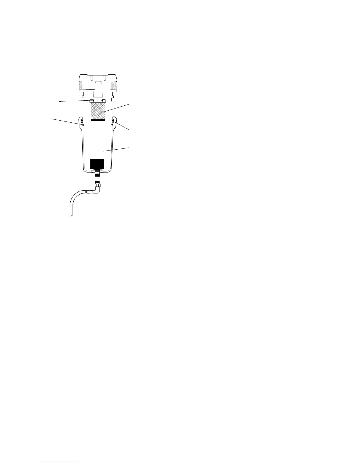
Replacing separator/filter element
Replace yearly or more often if pressure drop across the
dryer is excessive.
1. Shut-off compressed air supply to the dryer and
depressurize.
2. Remove top panel.
3. Remove two screws holding side panel and
remove side panel by sliding upward.
4. Disconnect drain tube from bulkhead fitting in cab-
inet base. To remove, press the plastic collar in,
toward the fitting, while pulling the tube out of the
fitting.
5. Remove bowl - push bowl up, turn bowl 1/8th turn
to your left, and pull straight down.
6. Clean filter bowl.
7. Replace element.
Replacing Complete Element
1. Pull off old element and discard.
2. Make certain o-ring inside top of replacement ele-
ment is in place and push element onto filter head.
Replacing Sleeve Only
1. Pull element straight down to remove.
2. Remove bolt and bottom cap and remove dispos-
able filter sleeve.
3. Clean separator core with soap and water in nec-
essary.
4. Slide new filter sleeve over separator core and
replace bottom cap and hand tighten bolt.
5. Make certain o-ring inside top of element is in
place and push element onto filter head.
6. After making sure that o-ring and wave spring
inside top of bowl are in place, reassemble bowl to
head.
NOTE: Make certain o-ring is generously lubricated.
NOTE: Wave spring ends should be pointed down to
prevent it from interfering with reassembly.
CAUTION
Dryer is a pressure containing device. Depressurize
before servicing.
Screen
Instructions/Parts
6Maintenance
7. Reconnect drain tube to bulkhead fitting by push-
ing tube into fitting until it locks in position.
8. Reinstall side and top panels.
9. Repressurize dryer and resume operation.
Automatic Condensate Drain
Check daily to make sure automatic drain is discharging.
Replace drain mechanism yearly.
1. Shut off compressed air supply to the dryer and
depressurize.
2. Remove top panel.
3. Remove two screws holding side panel then
remove side panel by sliding upward.
4. Disconnect drain tube from bulkhead fitting in cab-
inet base. To remove, press the plastic collar in,
toward the fitting, while pulling the tube out of the
fitting.
5. Remove bowl - push bowl up, turn 1/8th turn to
your left, and pull bowl straight down.
6. Remove drain tube fitting from bottom of bowl.
7. Remove old drain mechanism by turning knurled
fitting to the right (clockwise) and remove.
8. Install new drain mechanism. If necessary, use a
wire or pencil to guide the new mechanism into
place.
9. Reassemble drain tube fitting to bowl.
10. After making sure that large o-ring in filter head is
in place, reassemble bowl to head.
11. Reconnect drain tube to bulkhead fitting by push-
ing tube into fitting until it locks in position.
12. Reinstall top and side panels.
13. Repressurize dryer and resume operation.
Element o-ring
Bowl o-ring
Tube
Separator
Element
Wave Spring
Drain
Mechanism
Hose Barb

DRYAIRE REFRIGERATED AIR DRYERS
7
Troubleshooting
Problem Cause Solution
Water downstream of dryer. Residual free moisture remaining in down-
stream pipelines.
Air bypass system is open.
Inlet and outlet connections are reversed.
Temperatures surrounding air lines down-
stream of dryer have dropped below dry-
ers dew point rating.
Excessive free moisture (bulk liquid) at
dryer inlet.
Condensate not being automatically
drained. Drain mechanism is clogged or
inoperative or drain line is restricted or fro-
zen.
Dryer overloaded resulting in elevated
dew point.
Refrigeration system not functioning prop-
erly resulting in elevated dew point.
Blow out system with dry air.
Check valve positions.
Check for correct connection.
Insulate or heat trace air lines exposed to
low ambients or dry air to lower dew point.
Install separator ahead of dryer.
Replace drain mechanism if inoperative,
or open drain line.
Check inlet air temperature and pressure,
flow rate (compressor capacity) and ambi-
ent air temperature.
See “Refrigeration system not functioning
properly,” page 8.
High pressure drop across dryer Inlet air strainer clogged.
Excessive air flow.
Separator filter clogged.
Freezing of moisture in evaporator
because of refrigeration system improp-
erly functioning.
Clean inlet air strainer.
Check flow rate.
Replace filter sleeve.
See “Refrigeration system not functioning
properly,” page 8.
Fault Alarm Dryer overloaded resulting in high air out-
let temperature.
Refrigeration system not functioning prop-
erly resulting in high air outlet tempera-
ture.
Unit functioning normally but thermostatic
switch is malfunctioning or not securely
mounted.
Check inlet air temperature and pressure,
flow rate (compressor capacity) and ambi-
ent air temperature.
See “Refrigeration system not functioning
properly,” page 8.
Contact qualified refrigeration repairman
or manufacturer’s service department.

DRYAIRE REFRIGERATED AIR DRYERS
8
Refrigeration system not functioning prop-
erly
1. When dryer on/off in on or “I” posi-
tion
2. Refrigerant compressor cycles on
and off
Power failure.
Line disconnect switch open.
Blown fuses, open breaker.
Faulty wiring, loose terminals.
High or low ambient conditions.
Ambient air filter clogged.
Condenser fins clogged.
Fan motor or fan control switch malfunc-
tion.
Refrigerant leak.
Low voltage.
Check power to unit.
Close disconnect switch.
Check for continuity.
Have electrician check electrical connec-
tions.
Check minimum/maximum temperature
ranges.
Clean ambient air filter.
Clean condenser.
Replace fan motor or fan control switch.
Contact qualified refrigeration repairman
or manufacturer’s service department.
Check wiring.
Problem Cause Solution

DRYAIRE REFRIGERATED AIR DRYERS
9
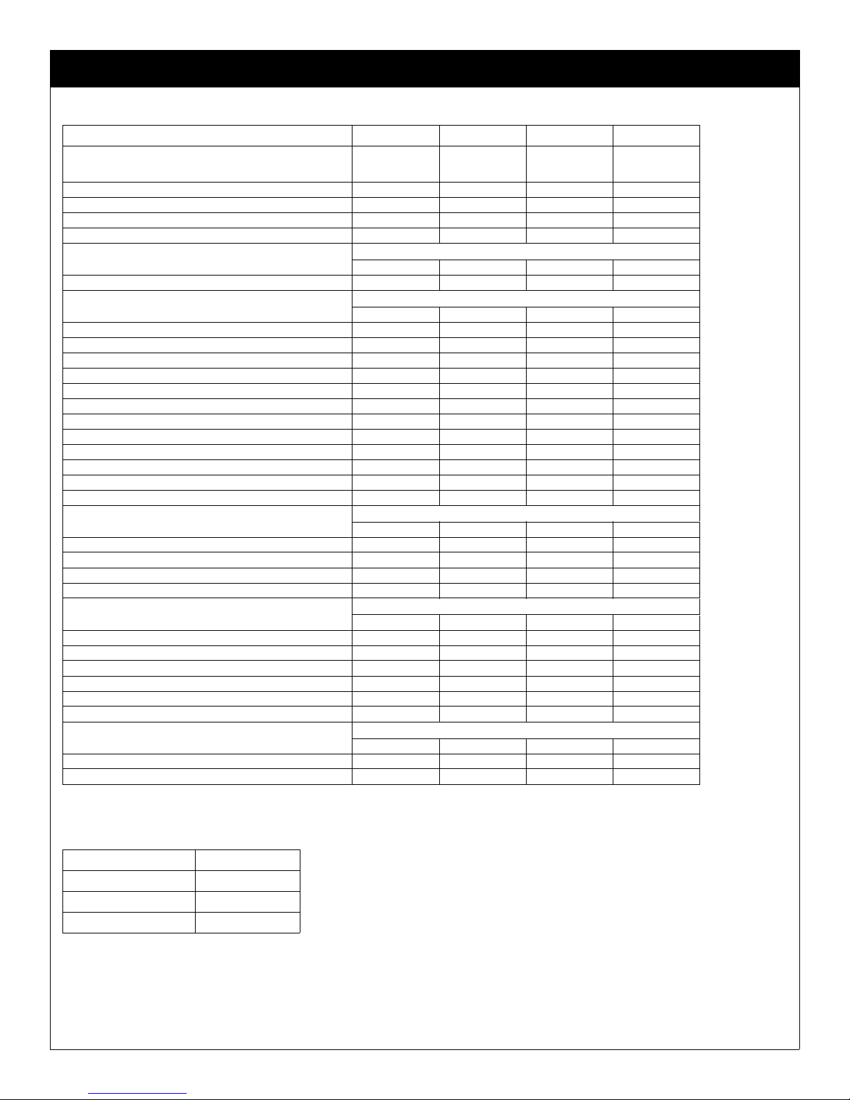
Specifications
Models 6880 through 6895
* Capacity @ 180°F (82°C) inlet temperature, 160°F (71°C) inlet pressure dew point, 95°F (35°C) ambient temperature, 50°F
(10°C) outlet pressure dew point, and less than 5 psi (0.35 kgf/cm2) pressure drop.
Description Model
6880 6885 6890 6895
Operating Conditions
Rated Capacity
@ 125 psig (8.8 kgf/cm2*)
scfm
m3/min.
60/50 hz
60/50 hz
25/21
0.71/0.59
35/27
0.99/0.76
50/50
1.42/1.42
75/61
2.12/1.7
Maximum Working Pressure 175 psig (12.3 kgf/cm2)
Maximum Inlet Temperature 180°F (82°C)
Minimum/Maximum Ambient Temp. 35-110°F (2-43°C)
Pressure Drop @
rated capacity
psi
kgf/cm2
60/50 hz
60/50 hz
3.3/2.4
0.23/0.17
4.7/2.9
0.33/0.20
4.5/4.5
0.32/0.32
3.8/2.2
0.27/0.15
Refrigeration System Data
Compressor Type Hermetic, Rotary, Permanent Split Capacitor
BTU/HR - Refrigeration Only
@ARSE-T Conditions 60/50 hz 6800/5500 6800/5500 12850/10100 12850/10100
Outlet Air Temperature
(nominal @ rated conditions) 155°F (68°C)
Refrigerant Type R-407C
Refrigerant Charge oz (grams) 60/50 hz 12.0 (340) 12.0 (340) 18.0 (510) 20.5 (581)
Suction Pressure Setting 67 psig (4.7 kgf/cm2)
Factory Test (design) Pressure
high side/low side 330/178 psig (23.2/12.5 kgf/cm2)
Condenser Fan Switch Setting (in-out) 240-280 psig (16.9-12.7 kgf/cm2)
Air Flow Across Condenser cfm
m3/min
60/50 hz
60/50 hz
280/235
7.9/6.7
280/235
7.9/6.7
620/515
17.6/14.6
620/515
17.6/14.6
Electrical Data
Unit 115/1/60
VAC/phase/hz 115/1/60
Minimum/Maximum Volts 98-127
Full Load Amps (FLA) 7.9 7.9 13.0 13.0
Branch Circuit Fuze Size (amps) 15 15 20 20
Compressor
Volts/phase/hz 115/1/60
Rated Load Amps (RLA) 6.7 6.7 11.1 11.1
Locked Rotor Amps (LRA) 37.0 37.0 63.0 63.0
Watts (input) 645 645 1250 1250
Overload Thermal and Current (Auto Reset)
Condenser Fan Motor
Volts/phase/Watts (output) 115/1/25 115/1/25 115/1/35 115/1/35
Full Load Amps (FLA) 1.2 1.2 1.6 1.6
Other Loads
Volts/amps/Watts 115/0.002/0.2 115/0.002/0.2 115/0.002/0.2 115/0.002/0.2
Unit
VAC/phase/hz
220-240/1/50
220-240/1/50
Minimum/Maximum Volts 198-264
Full Load Amps (FLA) 3.5 3.5 6.0 6.0
Branch Circuit Fuse Size (amps) 15 15 15 15
Compressor
Volts/phase/hz 220-240/1/50
Rated Load Amps (RLA) 2.9 2.9 5.1 5.1
Locked Rotor Amps (LRA) 14.0 14.0 28.0 28.0
Watts (input) 540 540 990 990
Overload Thermal and Current (Auto Reset)
Condenser Fan Motor
Volts/phase/Watts (output)
220-240/1/
18.3
220-240/1/
18.3
220-240/1/
25.6
220-240/1/
25.6
Full Load Amps (FLA) 0.6 0.6 0.8 0.8
Other Loads
Volts/amps/Watts
220-240/
0.002/0.4
220-240/
0.002/0.4
220-240/
0.002/0.4
220-240/
0.002/0.4
DRYAIRE REFRIGERATED AIR DRYERS
10
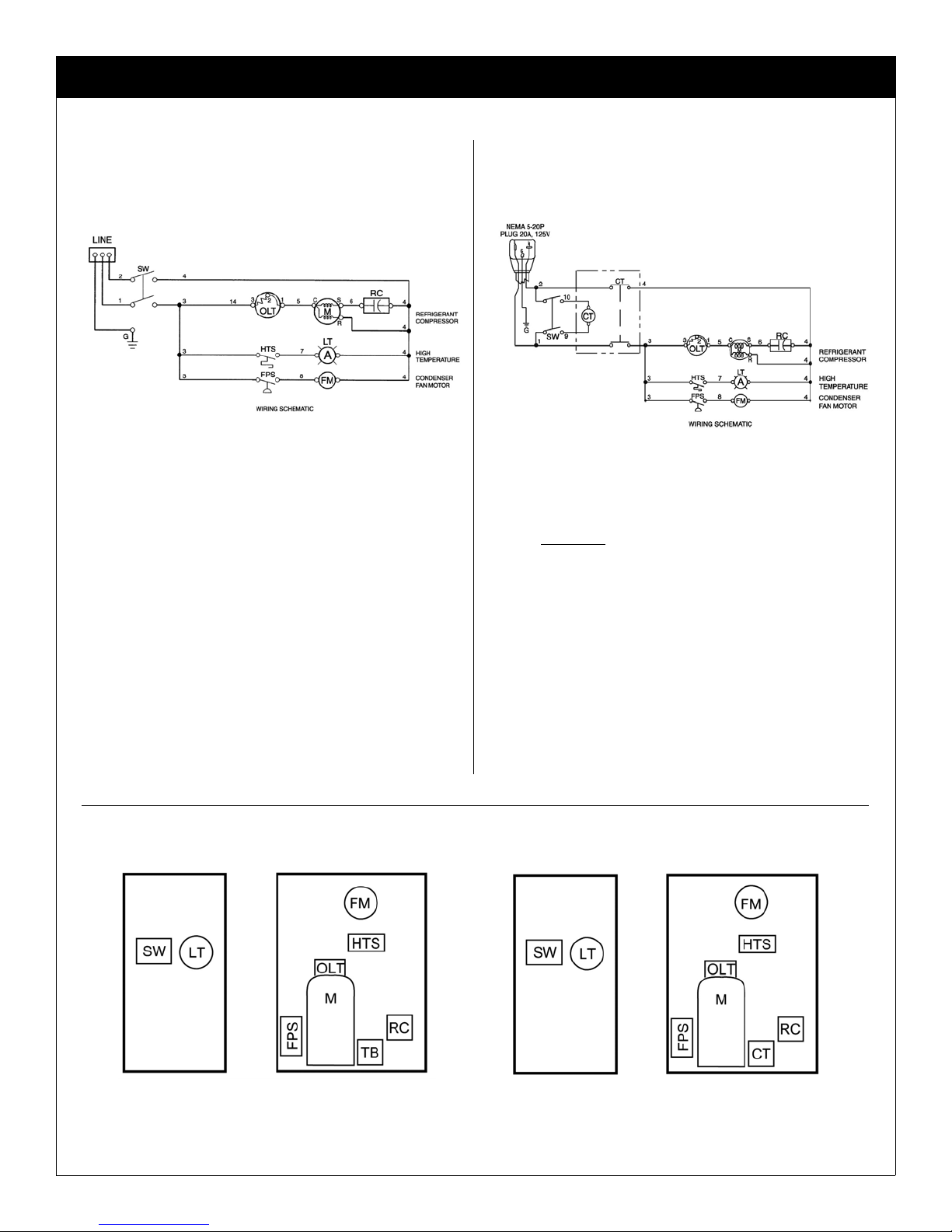
Electrical Schematics
All Models - All Voltages
Only Models 6890 and 6895 - 115-1-50/60 Only Models 6890 and 6895 - 115-1-50/60
LEGEND
SW On/Off Switch
OLT Thermal Overload
M Compressor Motor
RC Run Capacitor
HTS High Temperature Switch
LT Fault Light
FPS Fan Pressure Switch
FM Fan Motor
TB Terminal Block
CT Contactor with 115V Coil
All Models - All Voltages Only Models 6890 and 6895 - 115-1-50/60
COMPONENT LOCATIONS COMPONENT LOCATIONS
Front of Dryer
(Outside)
Front of Dryer
(Outside)
Right Side of Dryer
(Inside) Right Side of Dryer
(Inside)

Instructions/Parts
Electrical Schematics 11

DRYAIRE REFRIGERATED AIR DRYERS
12
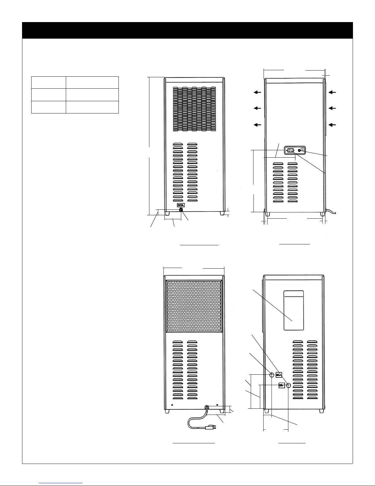
Dimensions and Weights
Models 6880 and 6885
Air Flow
1/4 in.
6 mm
Fault
Indicator
Light
On/Off
Switch
13/16 in.
21 mm
(TYP)
8 9/16 in.
217 mm
FRONT VIEW
3/16 in.
5 mm
12.5 in.
317 mm
5 1/16 in.
128 mm
1 in.
25 mm
1/4 in.
Drain Connection
4 1/8 in.
105 mm
LEFT SIDE VIEW
28 1/4 in.
718 mm
Serial
Number
Tag
10 1/8 in.
257 mm
Air outlet
1/2 in.
6 5/8 in.
168 mm
BACK VIEW
5 1/8 in.
130 mm
1 11/16 in.
41 mm
8 1/2 in.
216 mm
Air inlet
1/2 in.
1 1/2 in.
38 mm
4 1/8 in.
105 mm
11 5/16 in.
287 mm
Replaceable Ambient
Air Filter
12 7/8 in.
327 mm
1 9/16 in.
40 mm
10 1/8 in.
257 mm
RIGHT SIDE VIEW
Model Weight
6880 80 lbs (36 kg)
6885 81 lbs (37 kg)
DRYAIRE REFRIGERATED AIR DRYERS
13
Models 6890 and 6895
16 7/8 in.
425 mm 1/4 in.
6 mm
Air Flow
Fault
Indicator
Light
On/Off
Switch
13/16 in.
21 mm
15 1/4 in.
387 mm
FRONT VIEW
3/16 in.
5 mm
16 1/2 in.
419 mm
8 7/16 in.
213mm
1 in.
25 mm
1/4 in.
Drain Connection
LEFT SIDE VIEW
4 5/8 in.
117
1 1/2 in.
38 mm
36 3/4 in.
933 mm
BACK VIEW
2 5/16 in.
59 mm
6 7/8 in.
175 mm
6 5/16 in.
160 mm
9 1/8 in.
232 mm
Air Inlet
3/4 in.
Air Outlet
3/4 in.
Serial Tag
Number
1 9/16 in.
39 mm
5 1/16 in.
129 mm
RIGHT SIDE VIEW
16 7/8 in.
429 mm
Replaceable
Ambient Air Filter
Model Weight
6890 150 lbs (68 kg)
6895 155 lbs (70 kg)
DRYAIRE REFRIGERATED AIR DRYERS
14
Parts List
* Maintenance kits for the above models are available.
Maintenance Kits
Parts Description 6880 6885 6890 6895
Separator
*Separator/Filter Cartridge E9-16 E9-16 E9-20 E9-24
Filter Sleeve S9-16 S9-16 S9-20 S9-24
*Drain Mechanism 05.4170-08 05.4170-08 05.4170-08 05.4170-08
Bowl 03.0810-04 03.0810-04 03.0810-05 03.0810-06
*O-ring Bowl 9320.552.14 9320.552.14 9320.552.16 9320.552.16
Inlet (Compressed Air) Strainer
Strainer, inlet 4731.735.1 4731.735.1 4731.735.2 4731.735.2
*Screen, strainer 4731.735.5 4731.735.5 4731.735.7 4731.735.7
Electrical
Switch on/off 6110.706.7 6110.706.7 6110.706.7 6110.706.7
Light, Fault (amber) 115/1/60 6350.451.10 6350.451.10 6350.451.10 6350.451.10
Light, Fault (amber) 220-240/1/50 6350.451.11 6350.451.11 6350.451.11 6350.451.11
Cord Set 115/1/60 03.7133-10 03.7133-10 03.7133-11 03.7133-11
Cord Set 230/2/60 03.7133-24 03.7133-24 03.7133-25 03.7133-25
Cord Set 220-240/1/50 03.7133-12 03.7133-12 03.7133-12 03.7133-12
Capacitor, run 115/1/60 5910.103.17 5910.103.17 5910.103.13 5910.103.13
Capacitor, run 220-240/1/50 5910.103.18 5910.103.18 5910.103.49 5910.103.50
Capacitor, run 208-230/1/60 5910.103.18 5910.103.18 5910.103.49 5910.103.49
Overload, Compressor 115/1/60 5925.571.12 5925.571.12 5925.571.15 5925.571.15
Overload, Compressor 208-230/1/60 5925.571.13 5925.571.13 5925.571.16 5925.571.16
Overload, Compressor 220-240/1/50 5925.571.14 5925.571.14 5925.571.14 5925.571.14
Switch, fault light with conn. 03.7419-02 03.7419-02 03.7419-03 03.7419-03
Condenser Fan
Fan Motor 115/1/60 6105.226.2 6105.226.2 6105.226.7 6105.226.7
Fan Motor 220-240/1/50 6105.226.4 6105.226.4 6105.226.9 6105.226.9
Fan Motor 208-230/1/60 6105.226.4 6105.226.4 6105.226.9 6105.226.9
Fan Blade 115/1/60 6105.378.2 6105.378.2 6105.378.4 6105.378.4
Fan Blade 208-240-1-50/60 --- --- 6105.378.6 6105.378.6
Refrigeration System
Compressor 115/1/60 4130.106.67 4130.106.67 4130.106.70 4130.106.70
Compressor 208-230/1/60 4130.106.68 4130.106.68 4130.106.71 4130.106.71
Compressor 220-240/1/50 4130.106.69 4130.106.69 4130.106.72 4130.106.72
Condenser 4130.112.13 4130.112.13 4130.112.15 4130.112.15
Hot gas by-pass valve 4130.690.21 4130.690.21 4130.690.22 4130.690.22
Filter/Dryer 4130.165.12 4130.165.12 4130.165.12 4130.165.12
Fan Pressure Switch 4130.139.21 4130.139.21 4130.139.21 4130.139.21
Cabinet
*Filter, Ambient Air 4460.233.3 4460.233.3 4460.233.4 4460.233.4
Grommet (light and switch, front panel) 9320.302.11 9320.302.11 9320.302.11 9320.302.11
Foot, mounting 9330.230.2 9330.230.2 9330.230.2 9330.230.2
For Dryer Models Kit Number
6880, 6885 RDMK4B
6890 RDMK6B
6895 RDMK5B
DRYAIRE REFRIGERATED AIR DRYERS
15

All written and visual data contained in this document reflects the latest product information available at the time of publication.
Graco reserves the right to make changes at any time without notice.
Original instructions. This manual contains English. MM 310884
SHARPE MANUFACTURING • P.O. BOX 1441, MINNEAPOLIS, MN 55440-1441
1-800-742-7731, www.sharpe1.com
Copyright 2004, Graco Inc. is registered to ISO 9001
Revised 02/2011
Warranty
The manufacturer warrants the product manufactured by it, when properly installed, operated, applied, and maintained in accor-
dance with procedures and recommendations outlined in manufacturer’s instruction manuals, to be free from defects in material or
workmanship for a period as specified below, provided such defect is discovered and brought to the manufacturer’s attention within
the aforesaid warranty period.
The manufacturer will repair or replace any product or part determined to be defective by the manufacturer within the warranty
period, provided such defect occurred in normal service and not as a result of misuse, abuse, neglect or accident. Normal mainte-
nance items requiring routine replacement are not warranted. The warranty covers parts and labor for the warranty period unless
otherwise specified. Repair or replacement shall be made at the factory or the installation site, at the sole option of the manufac-
turer. Any service performed on the product by anyone other than the manufacturer must first be authorized by the manufacturer.
Unauthorized service voids the warranty and any resulting change or subsequent claim will not be paid. Products repaired or
replaced under warranty shall be warranted for the unexpired portion of the warranty applying to the original product.
The foregoing is the exclusive remedy of any buyer of the manufacturer’s product. The maximum damages liability of the manufac-
turer is the original purchase price of the product or part.
THE FOREGOING WARRANTY IS EXCLUSIVE AND IN LIEU OF ALL OTHER WARRANTIES, WHETHER WRITTEN, ORAL,
OR SATUTORY, AND IS EXPRESSLY IN LIEU OF THE IMPLIED WARRANTY OF MERCHANTABILITY AND THE IMPLIED
WARRANTY OF FITNESS FOR A PARTICULAR PURPOSE. THE MANUFACTURER SHALL NOT BE LIABLE FOR LOSS OR
DAMAGE BY REASON OF STRICT LIABILITY IN TORT OR ITS NEGLIGENCE IN WHATEVER MANNER INCLUDING DESIGN,
MANUFACTURE OR THE INSPECTION OF THE EQUIPMENT OR ITS FAILURE TO DISCOVER, REPORT, REPAIR, OR MOD-
IFY LATENT DEFECTS INHERENT THEREIN.
THE MANUFACTURER, HIS REPRESENTATIVE OR DISTRIBUTOR SHALL NOT BE LIABLE FOR LOSS OF USE OF THE
PRODUCT OR OTHER INCIDENTL OR CONSEQUENTIAL COSTS, EXPENSES, OR DAMAGES INCURRED BY THE BUYER,
WHETHER ARISING FROM BREACH OF WARRANTY, NEGLIGENCE OR STRICT LIABILITY IN TORT.
The manufacturer does not warrant any product, part, material, component, or accessory manufactured by others and sold or sup-
plied in connection with the sale of manufacturer’s products.
Warranty Period
Parts and labor for two (2) from the date of shipment from the factory; heat exchangers are covered (parts only) for an additional
three (3) years (total of five [5]). On units that manufacturer requests be returned to the factory, a one time removal/reinstallation
labor allowance as noted in the Service Warranty Policies and Procedures Handbook will apply. Freight to the factory from the
installation site and to the installation site from the factory will be paid by the manufacturer; means of transportation to be specified
by the manufacturer.
AUTHORIZATION FROM THE SERVICE DEPARTMENT IS NECESSARY BEFORE MATERIAL IS RETURNED TO THE FAC-
TORY OR IN-WARRANTY REPAIRS ARE MADE.
Product Registration
Thank you for the purchase of your Sharpe®product. We greatly appreciate your business.
Important reasons to register your product:
•Registration enables Sharpe to notify you if there is a problem with your product.
•Improved Product Development - Your input helps us continue to design products that meet your needs.
For the most up-to-date information and to register your product, please go to www.sharpe1.com and click on
“Register Product.”
This manual suits for next models
3
Table of contents
Other Sharpe Dehumidifier manuals


