Shenzhen VDWALL A6000 Series User manual
SHENZHEN VDWALL CO., LTD. www.vdwall.cn en.vdwall.cn
Add: Room 1001, 10th Floor, 4th Building, Fangda-city, Longzhu 4th Road, Nanshan District, 518073 Shenzhen,
China
Tel:+86-755-2675 0210 / 2650 1506 / 2663 6668
QQ:400-0660-628 Technical QQ group:422024594
1
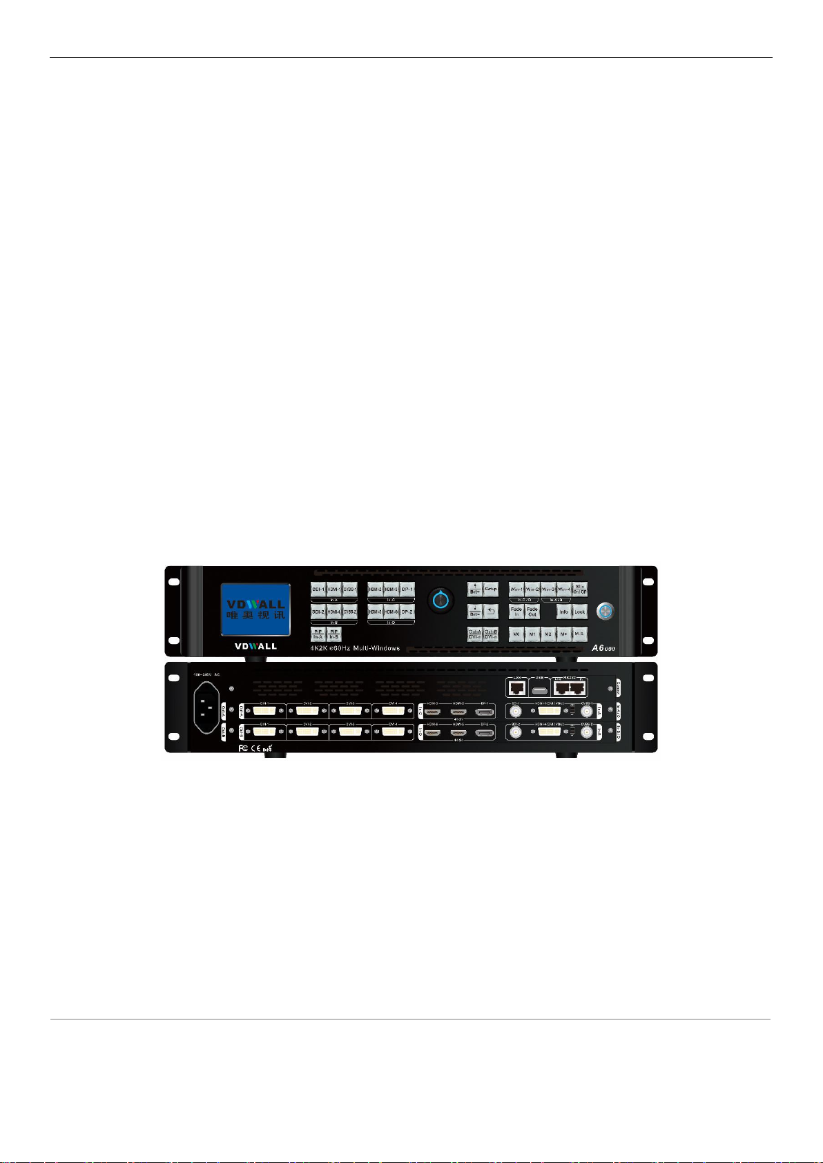
A6000 Series
4K Multi-Window Mosaic Processor
User Manual V1.0

A6000Series user manual www.vdwall.cn en.vdwall.cn
1
Contents
A6000 Series.............................................................................................................................................................................. 1
Chapter 1:Safety precautions............................................................................................................................................... 2
Chapter 2:Packing list............................................................................................................................................................ 3
Chapter 3:Hardware connection...........................................................................................................................................4
3-1 Rear panel signal port overview...................................................................................................................4
3-2 Port description............................................................................................................................................... 4
3-4 Technical specification................................................................................................................................... 6
3-5 Installation dimension.....................................................................................................................................8
Chapter 4: Front panel button description...........................................................................................................................10
4-1 Front panel button sketch map...................................................................................................................10
Chapter 5:User basic operation instruction......................................................................................................................13
5-1 Input card operation..................................................................................................................................... 13
5-2 Output card operation.................................................................................................................................. 15
Chapter 6: User setup menu..................................................................................................................................................21
6-1 Language setup............................................................................................................................................ 21
6-2 Video input setup.......................................................................................................................................... 22
6-3 Multi-Window setup......................................................................................................................................24
6-4 Output image setup......................................................................................................................................29
6-5 Communication setup.................................................................................................................................. 34
Chapter 7: System maintenance and related operation................................................................................................... 36
7-1 System random check and verification.....................................................................................................36
7-2 Data recovery................................................................................................................................................ 37
7-3 PC software import and export...................................................................................................................39
Chapter 8:Model code description..................................................................................................................................... 40

A6000Series user manual www.vdwall.cn en.vdwall.cn
2
Chapter 1:Safety precautions
Danger !
There is high voltage in the processor, to prevent any unexpected hazard, please do not
open the cover of the device,unless you are a maintenance personnel.
Warning !
1) This device shall not encounter water sprinkle or splash, please do not place anything containing
water on this device.
2) To prevent fire, keep this device far from any fire source.
3) If this device gives out any strange noise, smoke or smell, please immediately unplug the power cord
from receptacle, and contact local dealer.
4) Please do not plug or unplug DVI signal cable if the device is powered on.
Caution !
1) Please thoroughly read this manual before using this device, and keep it safe.
2) In the event of lighting or when you are not going to use the device for a long time, please pull the
power plug out of receptacle.
3) Nobody other than professional technicians can operate the device, unless they have been
appropriately trained or under guidance of technicians.
4) To prevent equipment damage or electric shock, please don’t fill anything in the vent of the device.
5) Do not place the device near any water source or anywhere damp.
6) Do not place the device near any radiator or anywhere under high temperature.
7) To prevent rupture or damage of power cords, please handle and keep them properly.
8) Please immediately unplug power cord and have the device repaired, when
1. Liquid splashes to the device.
2. The device is dropped down or cabinet is damaged.
3. Obvious malpractice is found or performance degrades.
A6000Series user manual Chapter 2 : Packing list
3
Chapter 2:Packing list
Please unpack the product with care, and then check whether all the following items are included in the
package. If anything is found missing, please contact the dealer.
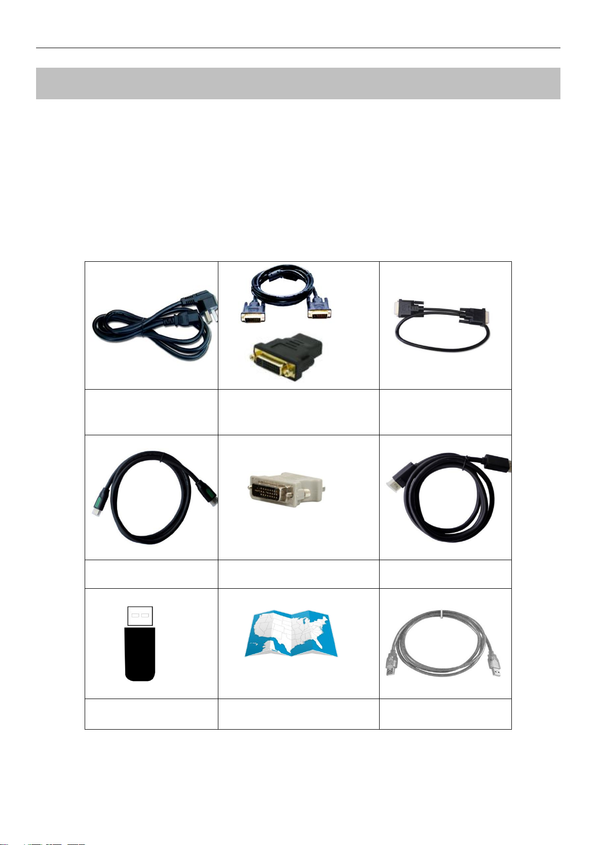
Standard accessories
The accessories supplied with this product may differ from the following pictures, but they are applicable for
the regions where you live (LED sending card is optional accessory)
1.5m Power cable X1
1.5m DVI cable
(Quantity depends on input
card quantity)
0.5m DVI cable
(Quantity depends on
output card quantity)
1.5m HDMI cable X1
DVI-I to VGA adapter X1
1.5m DP cable X1
Product data U disk X1
Quick operation instruction X1
1.5m USB cable X1
A6000Series user manual Chapter 3:Hardware connection
4
Chapter 3:Hardware connection
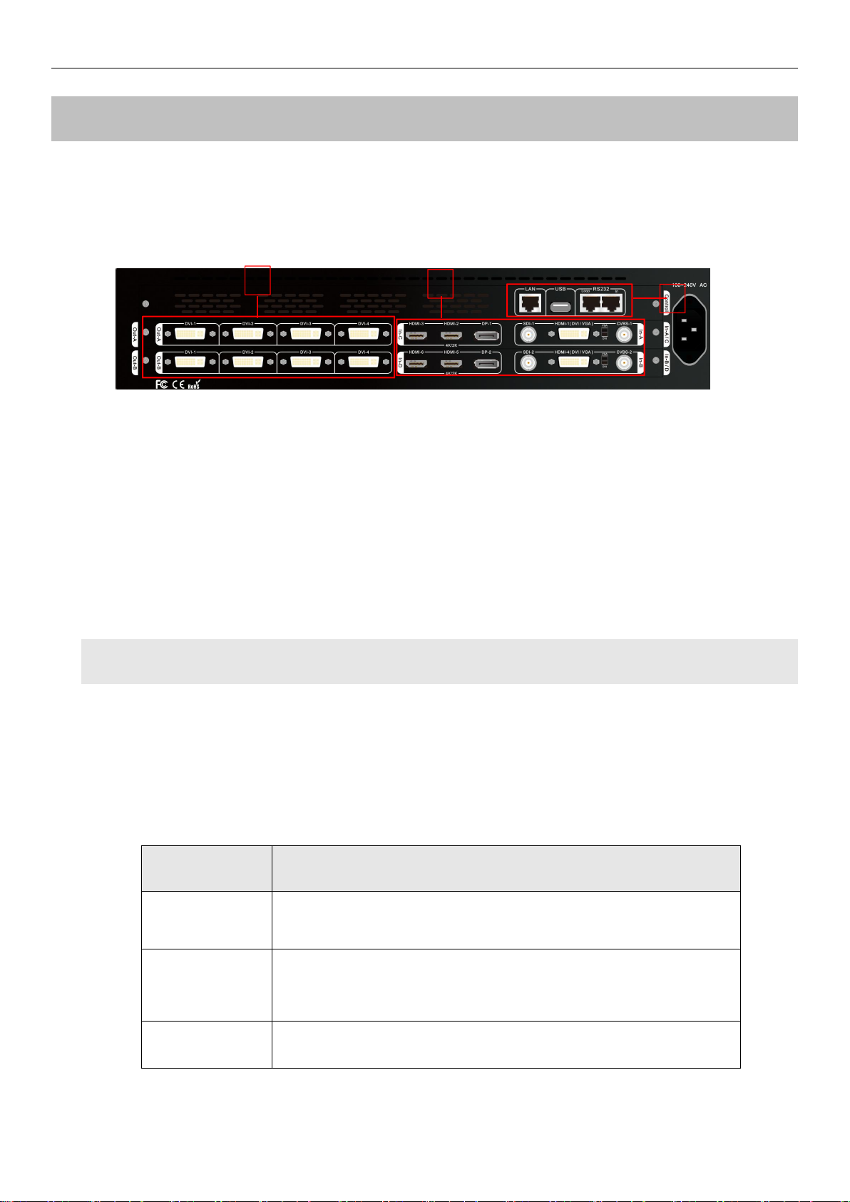
3-1 Rear panel signal port overview
2
3
1
Picture 3-1 Rear panel signal port
①Video input port ②Video output port ③Communication port
3-2 Port description
1. Video signal input
A6000 can assemble maximum 4 video input cards, the series numbers are In-A、In-B、In-C、In-D. In-A and
In-B are 2K input cards,In-C and In-D are 4K input cards .
Each 2K input card supports 4 channels of signal input, signal input port description as the following table:
Ports
Description
CVBS
1 channel of PAL/ NTSC format composite video input
HDMI(DVI/VGA)
1 channel of HDMI1.3 digital signal input ( compatible with DVI,can
choose VGA input via switch beside the port )
SDI
1 channel of SDI digital serial signal input

A6000Series user manual Chapter 3:Hardware connection
5
Each 4K video input card supports 3 channels of signal input, signal input port description as the following
table:
Ports
Description
HDMI
2 channel of HDMI2.0 digital signal input
DP
1 channel of DP1.2 digital signal input
2. Video signal output
A6000 can assemble maximum 2 output cards, series number are Out-A and Out-B. Each output
card can output 4 channels of DVI signal, output port description as the following table:
Ports
Description
DVI-1 ~ DVI-4
4 channels of DVI output ports, used to connect LED
sending card or monitor .
3. Communication port
Ports
Description
LAN
Local area network TCP/IP network control port
USB
USB communication port
RS232 In
Serial communication port, RS232 electrical level,connect to
PC RS232 port,for PC software control
RS232 Out
RS 232 cascading output port, RS232 electrical leve,several
processors can be controlled by single PC
A6000Series user manual Chapter 3:Hardware connection
6
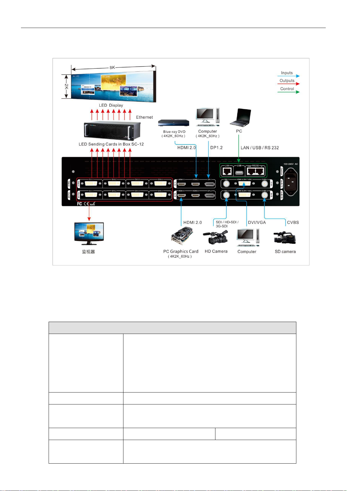
3-3 Hardware connection diagram
Picture 3-2 Hardware connection diagram
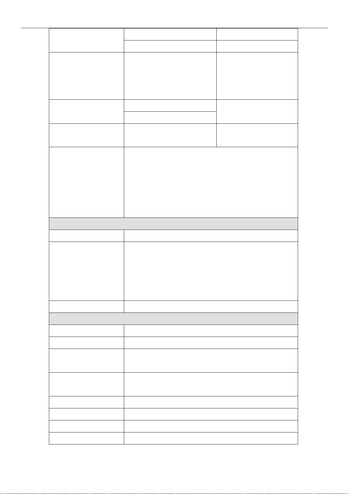
3-4 Technical specification
Input signal index
Quantity / type
4×HDMI 2.0(VESA/CEA-861)
2×DP1.2(VESA)
2×CVBS
2×DVI-I(VESA/CEA-861,support VGA/DVI/HDMI 1.3a)
2×SDI(SDI/HD-SDI/3G-SDI)
Composite video system
PAL/NTSC
Composite video
amplitude / Impedance
1V(p_p)/ 75Ω
VGA format
PC(VESA)
≤1920×1200_60Hz
VGA amplitude /
Impedance
R、G、B = 0.7 V(p_p)/ 75Ω
A6000Series user manual Chapter 3:Hardware connection
7
DVI /HDMI format
PC(VESA)
≤1920×1200_60Hz
HDMI1.3(CEA-861)
≤1080p_60Hz
SDI format
SMPTE259M-C
SMPTE 292M
SMPTE 274M/296M
SMPTE 424M/425M
480i_60Hz
576i_50Hz
720p、1080i、1080p
HDMI 2.0
(HDCP 2.2)
PC(VESA)
≤4096 x 2160_60Hz
HDMI2.0(CEA-861)
DP1.2
(HDCP 2.2)
DisplayPort1.2(VESA)
≤4096 x 2160_60Hz
Input port
CVBS:BNC/ 75Ω
VGA:24+5 DVI_I
DVI:24+5 DVI_I
HDMI 2.0:HDMI A mode
DP:DP port
SDI:BNC/ 75Ω
Output signal index
Quantity / type
8×DVI
DVI format
2160X1160_50Hz、2048X1200_50Hz、1920X1200_50Hz、
1920X1080_50Hz、1680X1440_50Hz、1440X1680_50Hz、
1200X1960_50Hz、1200x1600_60Hz、1440x1440_60Hz、
1600x1344_60Hz、1920×1080_60Hz、2160x960_60Hz、
User-defined output resolution
Output port
DVI OUT:24+1 DVI_D
Others
Control port
RS232/USB/LAN
Input voltage
100-240VAC 50/60Hz
Overall power
consumption
75W
Environment
temperature
0-45 ℃
Environment humidity
15-85%
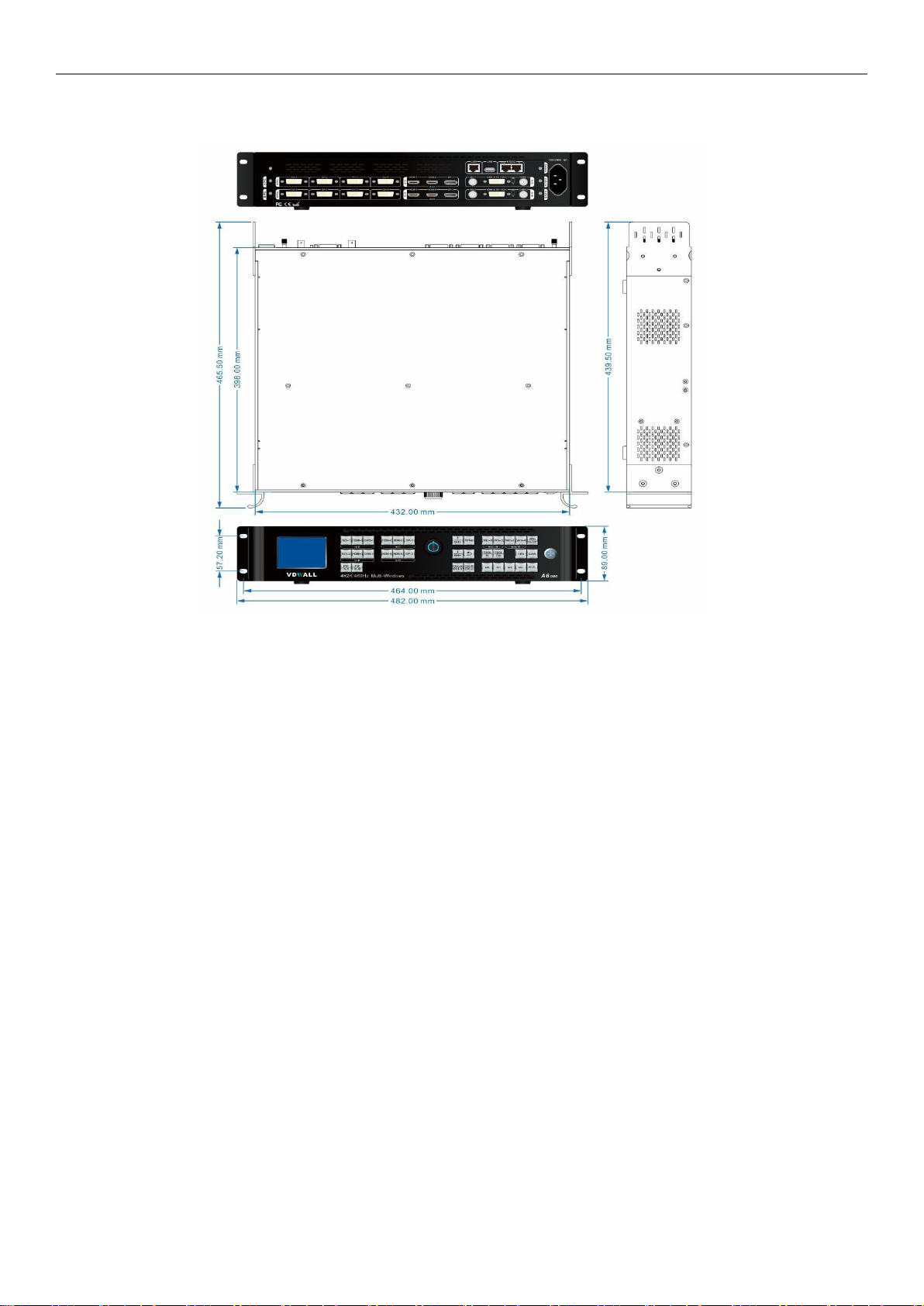
Product size
482(L) x 465.5(W) x 89(H)mm
Packing size
560(L) x 552(W) x 178(H)mm
Weight
G.W:10.8Kg, N.W:7.5Kg
A6000Series user manual Chapter 3:Hardware connection
8
3-5 Installation dimension
Picture 3-5a Installation dimension drawing

A6000Series user manual Chapter 3:Hardware connection
9
RS232 connection cable and wire order
Picture 3-5b RS232 connection cable and wire order
Note: 1. A is RS232 female connector
2. B is RJ45 connector
3. Accord with emergency decree,
The wires must be soft

A6000Series user manual Chapter 4:Front panel button description
10
Chapter 4: Front panel button description
4-1 Front panel button sketch map
1
3
2
Picture 4-1 Front panel button sketch map
①Input card button ②Setup button ③Other function button
1. Input signal selection button
Input signal selection button used to select signal source and open PIP, divided into 4 groups.
In-A input card button: SDI-1、HDMI-1、CVBS-1、PIP/In-A
In-B input card button: SDI-2、HDMI-4、CVBS-2、PIP/In-B
In-C input card button: HDMI-2、HDMI-3、DP-1
In-D input card button: HDMI-5、HDMI-6、DP-2
Note: press VGA button continually to adjust VGA signal, automatically fit screen.
2. Setup button
Configuration buttons: used to configure processor parameters
Setup:press to enter setup menu
↑、↓: up and down selection button
Knob:rotate Knob button adjust parameter value or select item

A6000 series user manual Chapter 5:Basic operation instruction
11
OK:press Knob /OK button, to save parameter
:back to previous menu
3. Output Card / Output Port selection button
Output Card and Output Ports selection button,used to select output DVI port
Out-A/DVI-n、Out-B/DVI-n
4. Multi-image function button
Win-1、Win-2、Win-3、Win-4: used to select target window
Win/OnOff: used to turn on / off selected window. Red indicator light up if corresponding
window lit up normally, indicator light off when close the selected window
Fade In、Fade Out: set selected window at bottom or on top with Fade in/Fade out switching effect
5. Brightness adjustment button
Brt+ ,Brt- or Knob: brightness adjustment buttons, when device is in operation state, use the
button to increase or decrease the output brightness
6. Information display button
Information display (Info): when device is in operation state, press Info button, processor LCD will
display current configuration and information. Press ↑or ↓to turn page, press button exit
7. Display mode button
Multi-window display mode, from 0 to 15 total 16 preset modes. Mode 0, 1 and 2 can be directly
recalled by pressing M0,M1 or M2 button, meanwhile the corresponding indicator will light up;
Mode 3 to 12 can be selected by pressing M+ button , the indicator of M+ will light up, then rotate
knob to select target mode. Mode 13-15 is used for backup, cannot be recalled directly;
MS is mode duplication button, can copy the parameters from source mode to destination mode. Each

A6000 series user manual Chapter 5:Basic operation instruction
12
display mode saves 4 configuration items and corresponding value:
A: image size and position ( including the input and output image )
B: overlay order of multi-layer
C: on-off status of window (Win On / Off status)
D: signal source of each window
8. Lock button
Lock button (Lock): lock function. Press to open front control button lock function, red indicator will
light up, all buttons in front panel will be invalid except Lock itself. Press Lock button three times
continually to unlock, the red indicator will light off.

A6000 series user manual Chapter 5:Basic operation instruction
13
Chapter 5:User basic operation instruction
After processor boot up, A6000 will automatically detect the quantity and configuration information of input
and output card. Processor LCD display interface varies from different customized boards assembled. The
following is standard display interface of full configuration (4 input boards, 2 output boards) .
In-A:HDMI1 PIP:off
In-B:CVBS2 PIP:SDI2
In-C:HDMI2
In-D:DP2
--------------------------------------
Multi Win:Win1->Win2->Win3->Win4
Input Card:In-D In-C In-A In-B
Multi Win Mode:M3
Output Mode: M0
Picture 5-1 Operation display interface
The top 4 rows show input signal source, for instance, In-B is CVBS2, PIP input signal is SDI2;
The fifth row "Multi Win: Win1->Win2->Win3->Win4" shows the overlay order from top to bottom;
The sixth row shows signal source of each window;
The seventh and eighth rows show multi win mode and output mode;
User can operate input and output card in operation state:
Input card operation includes input signal selection and PIP operation;
Output card operation includes output card selection, output port selection, display mode selection, mode
duplication and brightness adjustment;
Multi-win operation includes overlay order operation and mode duplication;
5-1 Input card operation
Under user operation state, input card operation includes: input card signal selection and PIP on/off.
1.Input card signal source selection
Input card A: when in PIP off state, press button SDI-1、
HDMI-1、
CVBS-1 to select signal source;
Input card B: when in PIP off state, press button SDI-2、HDMI-4、CVBS-2 to select signal source;
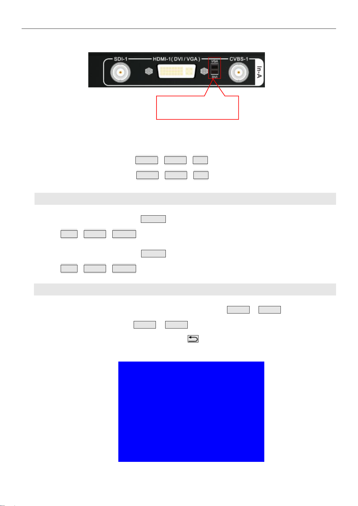
Note: HDMI-1 and HDMI-4 can access VGA signal, select VGA input or DVI/HDMI input by
toggling switch beside the DVI port.
A6000 series user manual Chapter 5:Basic operation instruction
14
Picture 5-1a DVI-I switch
Input card C: press button HDMI-2、HDMI-3、DP-1 to select signal source;
Input card D: press button HDMI-5、HDMI-6、DP-2 to select signal source;
2. Input card PIP operation
Input card A: press button PIP/In-A to enter or exit PIP. When in PIP ready state, press button
SDI-1、HDMI-1、CVBS-1 to select sub image sinal source;
Input card B: press button PIP/In-B to enter or exit PIP. When in PIP ready state, press button
SDI-2、HDMI-4、CVBS-2 to select sub image signal source;
3. VGA input signal automatic adjustment
For input card In-A and In-B, on occassion input signal is VGA, press HDMI-1 or HDMI-4 button to enter VGA
automatic adjustment menu, press HDMI-1 or HDMI-4 button again to automatically adjust VGA signal. May
need press several times to perfectly fit screen. Press to exit menu.
Tips
--------------------------------------
VGA Auto Adjust
Press <HDMI-1> to start
Press <Return> to cancel
--------------------------------------
Picture 5-1b VGA automatic adjustment
Switch up VGA signal
Switch down DVI/HDMI

A6000 series user manual Chapter 5:Basic operation instruction
15
5-2 Output card operation
Under user operation state, output card operation includes: output card display mode selection, output
brightness adjustment.
1. Output card display mode recall and mode duplication
A6000 multi-window display mode has 16 presets(M0-M15), select M0~M12 by pressing mode button,
M13~M15 are backup modes, can't be recalled directly.
Output mode operation procedure: under user operation state, rotate Knob button to select output mode,
press OK button to confirm and apply the output mode.
In-A:HDMI1 PIP:off
In-B:CVBS2 PIP:CVBS2
In-C:HDMI2
In-D:DP2
--------------------------------------
Multi Win:Win1->Win2->Win3->Win4
Input Card:In-D In-C In-A In-B
Multi Win Mode:M3
Output Mode: M0
Picture 5-2a Output mode switching
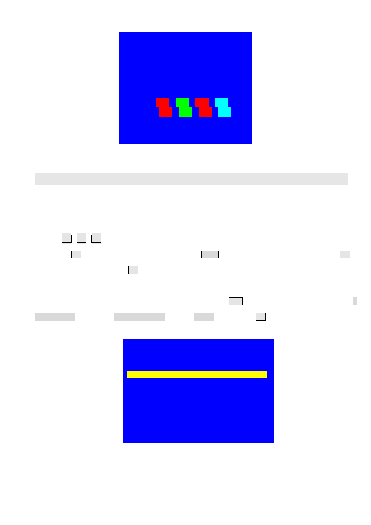
M.S. button operation procedure: under user operation state, press M.S. button to enter mode duplication
menu, select Source Mode and Destination Mode, on 3.Copy menu, press OK button, then output
parameters of Source Mode will be copied to Destination Mode.
Mode Copy(Output):
--------------------------------------
1.Source Mode M3
2. Destination Mode M4
3. Copy OK To Apply
-------------------------------------
Press <M.S.>switch to Multi Win Mode Copy
Picture 5-2b Output mode switching

A6000 series user manual Chapter 5:Basic operation instruction
16
2. Output card brightness setup
Output card brightness adjustment ranges from 0 – 255, “0” represents the lowest brightness level, press
Brt+ button to increase, and press Brt- button to decrease, or rotate Knob button to adjust value. In order to
guarantee sufficient grayscale, the default brightness value is 128.
Brightness(Out-A+Out-B)Default
--------------------------------------
1. Brightness 32 128
--------------------------------------
Picture 5-2c Output brightness setup
5-3 Multi-window operation
Multi-window operation mainly includes: output window on/off, overlay order operation, multi-window preset
mode operation and other related operations.
1. Output window on/off and overlay order operation
Output window on/off : under operation state, select target window by pressing(Win-1、Win-2、Win-3、
Win-4 ), then press Win/OnOff button to open or close selected window , Win/OnOff indicator light up
means display current window, indicator light off means close current window.
Multi-window overlay order operation: under operation state, select target window by pressing (Win-1、
Win-2、Win-3、Win-4), then press Fade In、Fade Out button to set the selected window at bottom or on
the top.
A6000 series user manual Chapter 5:Basic operation instruction
17
In-A:HDMI1 PIP:off
In-B:CVBS2 PIP:CVBS2
In-C:HDMI2
In-D:DP2
--------------------------------------
Multi Win:Win1->Win2->Win3->Win4
Input Card:In-D In-C In-A In-B
Multi Win Mode:M3
Output Mode:M0
Picture 5-3a Output card mode switching
2. Multi-window display mode operation
There are 16 preset multi-window display modes, M0 ~ M15, among which M0 ~ M12 is available for direct
recall , M13 ~ M15 is used for backup (cannot be recalled directly). M0 ~ M2 can be recalled directly by
pressing M0、
M1、
M2 button, the button indicator will light up after being selected; M3 ~M12 can be selected
by pressing M+ button into mode selection menu, rotate Knob button to select target mode, then press OK
button to confirm and apply, the M+ button will light up when recall M3 ~M12 .
Multi-window mode duplication: under user operation state, press M.S. button into mode copy menu, select
Source Mode and copy to Destination Mode, then on 3.Copy menu, press OK button to confirm and apply,
thus the parameters in source mode will be copied to destination mode.
Mode Copy(Multi Win):
--------------------------------------
1. Source Mode M3
2. Destination Mode M4
3. Copy OK To Apply
-------------------------------------
Press <M.S.> switch to Output Mode Copy
Picture 5-3b Multi-window mode copy

A6000 series user manual Chapter 5:Basic operation instruction
18
5-4 Other functions operation
Except above operations, there are lock button operation, system Info function and other related operations.
1. Lock button operation
Under operation state, press Lock button to activate function, other buttons will be invalid, only LAN, RS232,
USB control is active, thus to prevent remote control and front panel control conflict. A6000 will automatically
enter key lock state once receiving remote control instructions.
Under lock state,press Lock button three times continually to unlock.
Button Lock
--------------------------------------
Keypad Invalid
LAN Valid
RS232 Valid
USB Valid
--------------------------------------
Picture 5-4a Button lock
2. Check system information(Info)
Press Info button into System Info menu. Press ↑,↓button turning page,press to exit.
System Info menu as following.
System Info 1/9
--------------------------------------
Model:A6000
Version:V0.1.2
IP: 192.168.1.8
MASK:255.255.255.0
GATE:192.168.1.1
MAC:76-64-77-1A-2B-3A
Device ID:1
--------------------------------------
Picture 5-4b System info

A6000 series user manual Chapter 5:Basic operation instruction
19
System Info 2/9
--------------------------------------
Made data:2017-04
--------------------------------------
Picture 5-4c System info
Input - A(HD) 3/9
--------------------------------------
Version:V1.1.0
MAIN:HDMI-1
Input Signal:1080p_60Hz
PIP:Off
Input Signal:No Input
--------------------------------------
Picture 5-4d System info
Input - C(UHD) 5/9
--------------------------------------
Version:V1.1.0
Source:HDMI-2
Input Signal:No Input
--------------------------------------
Picture 5-4e System info
Other manuals for A6000 Series
1
Table of contents


