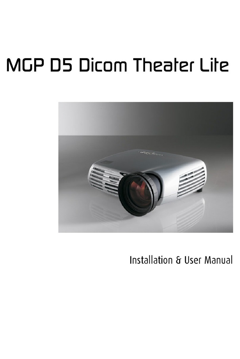
Barco R9841020 Cine VERSUM Master User manual

BARCOPROJECTION
Cine VERSUM 50
Cine VERSUM Master
Digital Link
Cine Versum 120
Cine Versum 80
CINE VERSUM SYSTEM
R9841020 Cine VERSUM Master/R9001870/R9005010 - R9001870 Cine VERSUM 80
R9005010 Cine VERSUM 50 - R9010090 Cine VERSUM 120
INSTALLATION MANUAL
03112003 R5976468/01

Barco nv Home Cinema
Noordlaan 5, B-8520 Kuurne
Phone: +32 56.36.84.30
Fax: +32 56.36.88.62
E-mail: [email protected]
Visit us at the web: www.homecinema.barco.com
Printed in Belgium

Copyright ©
All rights reserved. No part of this document may be copied, reproduced or translated. It shall not otherwise be recorded, transmitted or
stored in a retrieval system without the prior written consent of BARCO.
Changes
Barco provides this manual ’as is’ without warranty of any kind, either expressed or implied, including but not limited to the implied war-
ranties or merchantability and fitness for a particular purpose. Barco may make improvements and/or changes to the product(s) and/or the
program(s) described in this publication at any time without notice.
This publication could contain technical inaccuracies or typographical errors. Changes are periodically made to the information in this
publication; these changes are incorporated in new editions of this publication.
Trademarks
Brand and product names mentioned in this manual may be trademarks, registered trademarks or copyrights of their respective holders.
All brand and product names mentioned in this manual serve as comments or examples and are not to be understood as advertising for
the products or their manufactures.
Federal Communication Commission (FCC Statement)
This equipment has been tested and found to comply with the limits for a class B digital device, pursuant to Part 15 of the FCC rules.
These limits are designed to provide reasonable protection against harmful interference when the equipment is operated in a residential
environment. This equipment generates, uses, and can radiate radio frequency energy and, if not installed and used in accordance with the
instruction manual, may cause harmful interference to radio communications. Operation of this equipment in a residential area is likely to
cause harmful interference in which case the user is encouraged to try to correct the interference by one or more of the following measures.
Introduction to the user :
If this equipment does cause interference to radio or television reception, the user may try to correct the interference by one or more of the
following measures :
• Re-orientation of the receiving antenna for the radio or television.
• Relocate the equipment with respect to the receiver.
• Plug the equipment into a different outlet so that the equipment and receiver are on different branch circuits.
• Fasten cables connectors to the equipment by mounting screws.
The use of shielded cables is required to comply within the limits of Part 15 of FCC rules and EN55022.
Guarantee and Compensation
Barco provides a guarantee relating to perfect manufacturing as part of the legally stipulated terms of guarantee. On receipt, the purchaser
must immediately inspect all delivered goods for damage incurred during transport, as well as for material and manufacturing faults Barco
must be informed immediately in writing of any complaints.
The period of guarantee begins on the date of transfer of risks, in the case of special systems and software on the date of commissioning,
at latest 30 days after the transfer of risks. In the event of justified notice of compliant, Barco can repair the fault or provide a replacement
at its own discretion within an appropriate period. If this measure proves to be impossible or unsuccessful, the purchaser can demand a
reduction in the purchase price or cancellation of the contract. All other claims, in particular those relating to compensation for direct or
indirect damage, and also damage attributed to the operation of software as well as to other services provided by Barco, being a component
of the system or independent service, will be deemed invalid provided the damage is not proven to be attributed to the absence of properties
guaranteed in writing or due to the intent or gross negligence or part of Barco.
If the purchaser or a third party carries out modifications or repairs on goods delivered by Barco, or if the goods are handled incorrectly,
in particular if the systems are commissioned operated incorrectly or if, after the transfer of risks, the goods are subject to influences not
agreed upon in the contract, all guarantee claims of the purchaser will be rendered invalid. Not included in the guarantee coverage are
system failures which are attributed to programs or special electronic circuitry provided by the purchaser, e.g. interfaces. Normal wear as
well as normal maintenance are not subject to the guarantee provided by Barco either.
The environmental conditions as well as the servicing and maintenance regulations specified in the this manual must be complied with by
the customer.


Table of contents
TABLE OF CONTENTS
1. Safety Instructions.................................................................................................. 5
1.1 General Safety Instructions . ............................................................................................................ 5
1.1.1 General Instructions . . ............................................................................................................ 5
1.1.2 Electrical Safety .................................................................................................................. 6
1.1.3 Protection on Servicing........................................................................................................... 6
1.1.4 Safety on Cleaning . . . ............................................................................................................ 7
1.1.5 Safety on Shipping ............................................................................................................... 7
1.2 Display Related Safety Instructions .................................................................................................... 7
1.2.1 Cine VERSUM 50 ................................................................................................................ 7
1.2.1.1 On installation site ......................................................................................................... 7
1.2.1.2 On product specifications. ................................................................................................. 8
1.2.2 Cine VERSUM 80 and Cine VERSUM 120 ..................................................................................... 8
1.2.2.1 Heat and Fire Hazards .................................................................................................... 8
1.2.2.2 Safety on Installation ...................................................................................................... 9
1.2.2.3 Protection from High Intensity Light Beam and Ultraviolet Radiation.................................................... 9
2. Cine VERSUM System.............................................................................................11
2.1 Digital Video Distribution Concept..................................................................................................... 11
2.2 Digital Video Distribution Parts ........................................................................................................ 11
2.2.1 Cine VERSUM Master ..........................................................................................................12
2.2.2 Cine VERSUM 50 ...............................................................................................................12
2.2.3 Cine VERSUM 80 ...............................................................................................................13
2.2.4 Cine VERSUM 120..............................................................................................................13
2.2.5 Digital Link.......................................................................................................................13
3. Unpacking ...........................................................................................................15
3.1 Unpacking Cine VERSUM Master.....................................................................................................15
3.2 Unpacking Cine VERSUM 80 .........................................................................................................16
3.3 Unpacking Cine VERSUM 120........................................................................................................17
3.4 Unpacking Cine VERSUM 50 .........................................................................................................18
4. Dimensions..........................................................................................................19
4.1 Cine VERSUM Master.................................................................................................................19
4.2 Cine VERSUM 80......................................................................................................................21
4.3 Cine VERSUM 120 ....................................................................................................................23
4.4 Cine VERSUM 50......................................................................................................................24
5. Location of Controls...............................................................................................27
5.1 On Cine VERSUM Master.............................................................................................................27
5.2 On Cine VERSUM 50..................................................................................................................27
5.3 On Cine VERSUM 80..................................................................................................................28
5.4 Cine VERSUM 120 ....................................................................................................................29
5.5 On InfraRed Remote Control..........................................................................................................30
6. Installation Guidelines.............................................................................................33
6.1 Projector Installation Guidelines.......................................................................................................33
6.1.1 General Installation Guidelines . ................................................................................................33
6.1.2 Image Projection ................................................................................................................34
6.1.2.1 Cleaning the lens .........................................................................................................34
6.1.2.2 Image Projection configurations..........................................................................................34
6.1.2.3 Projector distance adjustment............................................................................................36
6.1.2.4 Projector installation requirements.......................................................................................38
6.1.2.5 Lens Control ..............................................................................................................38
6.1.2.6 Ceiling Mount for Cine VERSUM 80 Cine VERSUM 120 . ..............................................................40
6.2 Plasma Screen Installation Guidelines................................................................................................41
6.2.1 About Installation of the Unit ....................................................................................................41
6.2.2 Installation using the Wall mount kit ............................................................................................41
6.2.3 Installation using the Table mount kit...........................................................................................42
7. Connections.........................................................................................................45
7.1 Power Supply Connection . . ...........................................................................................................45
7.1.1 Supplied Power Cords . . . . . . ....................................................................................................45
7.1.2 Power Connection Cine VERSUM Master .....................................................................................45
7.1.3 Power Connection Cine VERSUM 80 . . . . . .....................................................................................46
7.1.4 Power Connection Cine VERSUM 120 . . . . .....................................................................................47
7.1.5 Power Connection Cine VERSUM 50 . . . . . .....................................................................................47
7.2 Connection for Preview and Communication . . . . .....................................................................................48
7.2.1 Connection for Preview Monitors . . . ............................................................................................48
7.2.2 Connection for Communication . ................................................................................................49
7.2.3 Network Connection . . ...........................................................................................................50
7.3 Digital Link to Display Modules . . . . ....................................................................................................51
7.3.1 Cine VERSUM System Link ....................................................................................................51
7.3.2 Digital Link to One Display......................................................................................................52
R5976468 CINE VERSUM SYSTEM 03112003 1
Table of contents
7.3.3 Digital Link to More Displays (Loop-through). . .................................................................................53
7.3.4 Digital Link Cable for long distances............................................................................................54
7.4 Connection to Video Equipment.......................................................................................................55
7.4.1 Input Connection per Module . . . ................................................................................................56
7.4.2 Installation of an Input module . . ................................................................................................58
8. Operating the Remote Control...................................................................................61
8.1 Battery Insertion in the Remote Control...............................................................................................61
8.2 Operating the Remote Control.........................................................................................................62
8.3 Address setting for the Remote Control...............................................................................................63
9. Points of Similarity between Graphical display and On Screen Menus ..................................65
9.1 Explanation about differences in menu displays . .....................................................................................65
10.Overview GUI Menu Screens.....................................................................................69
10.1Overview Main menu..................................................................................................................69
10.2Overview Image Settings..............................................................................................................70
10.3Overview Advanced Settings..........................................................................................................71
10.4Overview Installation ..................................................................................................................72
10.5Overview Service......................................................................................................................75
11.Powering on/off the Cine VERSUM System ...................................................................77
11.1Powering ON the Cine VERSUM System ............................................................................................77
11.2Status of the System after powering up...............................................................................................77
11.3Display Info ’New Display’ and ’Lost Display’.........................................................................................78
12.Image Projection after Powering Up ............................................................................81
12.1Image Projection Using the Jog Dial on Cine VERSUM Master.....................................................................81
12.2Image Projection Using the Remote Control .........................................................................................81
12.3Lamp Mode Set Up for Cine VERSUM 120 Only.....................................................................................82
12.3.1Lamp Mode Set Up Single/Dual (Image Settings menu) ......................................................................82
12.3.2Lamp Mode Set Up Economic/Normal (Image Settings menu) . ..............................................................83
12.3.3Lamp mode/Power set up in Display Settings menu. . . . . ......................................................................83
13.Projection Stop (Standby or Economic Standby mode).....................................................85
13.1Projection Stop Using the Selection Wheel...........................................................................................85
13.2Projection Stop Using the Remote Control ...........................................................................................86
13.2.1Direct System Shutdown (standby). ............................................................................................86
13.2.2System Shutdown (standby) via screen menu .................................................................................86
14.Switching linked displays To and Out Standby ...............................................................89
14.1Switching by means of the Cine VERSUM Master . . .................................................................................89
14.1.1Switching In/Out Standby using the Jog Dial. . .................................................................................89
14.1.2Switching In/Out Standby using the Remote Control .. . . ......................................................................90
14.2Direct Switching of the Linked Display................................................................................................91
14.2.1Switching a specific display In/Out standby....................................................................................91
15.Module Address Read out/Change..............................................................................93
15.1Default address of the Modules . . . ....................................................................................................93
15.2Reading out/Changing the stored addresses. . . . .....................................................................................93
15.2.1Reading out the stored address ................................................................................................93
15.2.2Changing the stored addresses ................................................................................................94
16.Input Source File Service .........................................................................................97
16.1About Stored files......................................................................................................................97
16.2Loading a File..........................................................................................................................97
16.3Editing a File...........................................................................................................................99
16.4File identification . . . . ...................................................................................................................99
16.5Rename a file .........................................................................................................................102
16.6Copy a file.............................................................................................................................102
16.7Delete a file ...........................................................................................................................103
16.8Delete all files.........................................................................................................................104
16.9File options............................................................................................................................104
17.Adjusting the Picture ............................................................................................ 105
17.1Setup Video and RGB module for the input signal type. ............................................................................105
17.2Adjusting the Image Orientation......................................................................................................106
17.3Adjusting the Image Aspect Ratio....................................................................................................107
17.4Adjusting the Decoding Standard . ...................................................................................................109
17.5White Peak Set up....................................................................................................................109
17.6Keystone Correction..................................................................................................................110
17.6.1Setting the Keystone correction: Global or on a File .........................................................................110
17.6.2Applying the Keystone correction..............................................................................................111
17.7Adjusting the Image Shift and Size ..................................................................................................112
17.7.1Adjusting the Image Shift ......................................................................................................112
17.7.2Adjusting the Image Size ......................................................................................................113
17.8Outline the displayed Image (Blanking)..............................................................................................113
2R5976468 CINE VERSUM SYSTEM 03112003

Table of contents
17.9Alignment of the Input Balance . . . ...................................................................................................114
17.9.1Input Balance Selection . .. . . ...................................................................................................115
17.9.2Input Balance Adjustment. . . ...................................................................................................116
17.10Phase adjustment for Computer signals ...........................................................................................117
17.11Gamma Correction ..................................................................................................................117
17.12Adjusting the Color Temperature ...................................................................................................118
17.12.1Selecting the preset Color Temperature .....................................................................................119
17.12.2Customizing the Color Temperature .........................................................................................120
17.13Adjusting the Picture Controls ......................................................................................................122
17.13.1Master Adjustment of the Analog Controls ..................................................................................123
17.13.2Analog Controls adjustment per Display.....................................................................................123
17.13.2.1Via Cine VERSUM Master.............................................................................................124
17.13.2.2Via Display with Remote Control only .................................................................................125
18.Additional settings Cine VERSUM Master ................................................................... 127
18.1Output Resolution set up.............................................................................................................127
18.2Display Internal Generated Pattern . . . ...............................................................................................128
18.3Shutdown Automatic when no signal . ...............................................................................................129
18.4Source Transition.....................................................................................................................130
18.5On Screen Display Configuration ....................................................................................................130
18.5.1About the OSD (Menu, Bar Scale and Message) . ............................................................................130
18.5.2Status Change of the OSD ....................................................................................................131
18.5.3On Screen Display Position Alignment........................................................................................132
18.6On-Screen Display Language . . . . . ...................................................................................................132
18.7Display Name Change . ..............................................................................................................133
19.Picture in Picture (PIP) .......................................................................................... 135
19.1Turning On/Off the Picture in Picture ................................................................................................135
19.2Selecting Input Source for PIP Window. . . ...........................................................................................135
19.3Configuration of the PIP Window . ...................................................................................................136
20.Cine VERSUM Master Settings & Info ........................................................................ 139
20.1Service Menu .........................................................................................................................139
20.2Cine VERSUM Master Identification . ................................................................................................139
20.3Cine VERSUM Master Password....................................................................................................140
20.4Cine VERSUM Master Address......................................................................................................141
20.4.1About the Cine VERSUM Master Address ....................................................................................141
20.4.2Cine VERSUM Master Address change . . ....................................................................................142
20.4.3Selecting the Transmission Speed ............................................................................................143
20.4.4Selecting the Interface standard (RS232/RS422). ............................................................................143
20.4.5RS422 data bus termination...................................................................................................144
20.4.6Diagnosis . . . . . ..................................................................................................................144
21.Maintenance Indicators ......................................................................................... 145
21.1Display Information...................................................................................................................145
21.2Display Diagnosis. . . ..................................................................................................................147
21.3ColorWheel IndexCine VERSUM 80 . . ...............................................................................................148
21.4Test Pattern...........................................................................................................................149
Index.................................................................................................................... 153
R5976468 CINE VERSUM SYSTEM 03112003 3

Table of contents
4R5976468 CINE VERSUM SYSTEM 03112003

1. Safety Instructions
1. SAFETY INSTRUCTIONS
Overview
• General Safety Instructions
• Display Related Safety Instructions
1.1 General Safety Instructions
Overview
• General Instructions
• Electrical Safety
• Protection on Servicing
• Safety on Cleaning
• Safety on Shipping
1.1.1 General Instructions
Scope
This document includes safety considerations of the Cine VERSUM System. Throughout this manual, the term SERVICE PERSON-
NEL refers to persons having appropriate technical training and experience necessary to be knowledgeable of potential hazards
to which they are exposed (including, but not limited to HIGH VOLTAGE ELECTRIC and ELECTRONIC CIRCUITRY and HIGH
BRIGHTNESS PROJECTORS) in performing a task, and of measures to minimize the potential risk to themselves or other persons.
The term USER and OPERATOR refers to any person other than SERVICE PERSONNEL, AUTHORIZED to operate the installed
digital video distribution system.
General safety instructions
• Before operating your digital video distribution system, please read this manual thoroughly, and retain it for future use.
• Installation and preliminary adjustments should be performed by qualified BARCO service personnel or authorized BARCO
service dealers.
• All warnings on the system parts and in the documentation manual should be adhered to.
• All instructions for operating and use of this equipment must be followed precisely.
• All local installation codes should be adhered to.
Owner’s Record
The part number and serial number are indicated on the registration plate which is located at the rear of the Cine VERSUM 50, at
the bottom of the Cine VERSUM Master, Cine VERSUM 80 and Cine VERSUM 120. Record these numbers in the spaces of the
table provided below. Refer to them whenever you call upon your BARCO dealer regarding these products.
Name Parts Number Serial Number Dealer
Cine VERSUM Master
Cine VERSUM 50
Cine VERSUM 80
Cine VERSUM 120
R5976468 CINE VERSUM SYSTEM 03112003 5

1. Safety Instructions
Shock Hazard
The lightning flash with an arrowhead within a triangle is intended to tell the user that
parts inside this product are risk of electrical shock to persons.
The exclamation point within a triangle is intended to tell the user that important
operating and/or servicing instructions are included in the technical documentation f
o
this equipment.
Image 1-1
1.1.2 Electrical Safety
Ratings & Grounding
• These products should be operated from an AC power source. Check if the mains voltage and the load matches the product
electrical ratings.
• A grounded three-core power cable has to be used. Connect the power cord by inserting it in a grounded electrical outlet,
making sure that the cord is properly grounded.
• If you are unable to install the AC Requirements, contact your electrician. Do not defeat the purpose of the grounding.
• Always connect this appliance to an electrically grounded outlet. Never use a ground bypass (cheater) adapter.
General
• Always plug power cord into appliance before plugging into outlet.
• Do not allow anything to rest on the power cord. Do not locate this product where persons will walk on the cord.
• Always unplug appliance from electrical outlet before cleaning and servicing and when not in use. Never yank cord to pull plug
from outlet. Grasp plug and pull to disconnect.
• Do not operate appliance with a damaged cord or if the appliance has been dropped or damaged - until it has been examined
by a qualified serviceman.
• Position the cord so that it will not be tripped over, pulled, or contact hot surfaces.
• If an extension cord is necessary, a cord with a current rating at least equal to that of the appliance should be used. Cord rated
for less amperage than the appliance may overheat.
• Let appliance cool completely before storing. Remove cord from appliance when storing.
• Never push objects of any kind into this product through cabinet slots as they may touch dangerous voltage points or short out
parts that could result in a risk of fire or electrical shock.
• Never spill liquid of any kind on the product. Should any liquid or solid object fall into the cabinet, unplug the set and have it
checked by qualified service personnel before resuming operations.
• Lightning - For added protection for this video product during a lightning storm, or when it is left unattended and unused for
long periods of time, unplug it from the wall outlet. This will prevent damage to the projector due to lightning and AC power-line
surges.
1.1.3 Protection on Servicing
Attempts to alter the factory-set internal controls or to change other control settings not specially discussed
in this manual can lead to permanent damage to the Projection Unit and cancellation of the warranty.
Servicing
Do not attempt to service the installed modules yourself, as opening or removing covers may expose you to dangerous voltage
potential and risk of electric shock! Refer all projector service to a qualified BARCO service center.
Call for service in the following conditions :
• When the power cord or plug is damaged or frayed.
• If liquid has been spilled into the modules.
• If the product has been exposed to rain or water.
• If the product does not operate normally when the operating instructions are followed. Adjust only those controls that are
covered by the operating instructions since improper adjustment of the other controls may result in damage and will often
require extensive work by a qualified technician to restore the product to normal operation;
• If the product has been dropped or the cabinet has been damaged;
• If the product exhibits a distinct change in performance, indicating a need for service.
6R5976468 CINE VERSUM SYSTEM 03112003

1. Safety Instructions
Replacement Parts
When replacement parts are required, be sure the service technician has used original BARCO replacement parts or authorized
replacement parts which have the same characteristics as the BARCO original part. Unauthorized substitutions may result in de-
graded performance and reliability, fire, electric shock or other hazards. Unauthorized substitutions may void warranty.
Safety Check
Upon completion of any service or repairs to these modules, ask the service technician to perform safety checks to determine that
the modules are in proper operating condition.
Lamp Explosion Hazard
P-VIPRlamps are under high pressure. The lamp must be handled with great care. They may explode if dropped or
mishandled. Never try to disassemble the lamp housing.
Lamp disposal:
For disposal of spent lamps, always consult federal, state, local and provincial hazardous waste disposal rules and regulations to
ensure proper disposal.
1.1.4 Safety on Cleaning
Cabinet
Unplug this product from the wall outlet before cleaning. Do not use liquid cleaners or aerosol cleaners. Use a damp cloth for
cleaning.
To keep the cabinet looking brand-new, periodically clean it with a soft cloth. Stubborn stains may be removed with a cloth lightly
dampened with mild detergent solution. Never use strong solvents, such as thinner or benzine, or abrasive cleaners, since these
will damage the cabinet.
Optical Performances
To ensure the highest optical performance and resolution, the projection lenses are specially treated with an anti-reflective coating,
therefore : AVOID TOUCHING THE LENS FACE. To remove dust on the lens, use a soft dry cloth. Do not use a damp cloth,
detergent solution, or thinner. Follow the lens cleaning procedure in the Owners Manual.
1.1.5 Safety on Shipping
Original Shipping package
Save the original shipping packing material; they will come in handy if you ever have to ship one of your installed modules. For
maximum protection, repack your set as it was originally packed at the factory.
1.2 Display Related Safety Instructions
1.2.1 Cine VERSUM 50
Overview
• Oninstallationsite
• On product specifications
1.2.1.1 On installation site
Transportation
• Any transportation of the unopened unit in its packaging should be done by two or more persons. To avoid injury or damage,
do not lift the package by its packing bands.
• When transporting or storing the unit, always position it vertically – NEVER horizontally. Horizontal transportation or storage
invalidates the product warranty.
• In transportation or storage of products in original packing, NEVER stack more than three units high. This warning is also
indicated on he upper face of the carton.
• For transportation or storage, observe the warnings and instructions on the upper face of the carton.
R5976468 CINE VERSUM SYSTEM 03112003 7

1. Safety Instructions
Nearby equipment
If air conditioning ducts or lamps, etc. are located near the installation site, the attendant dust, extreme temperatures, humidity, and
condensation may become sources of trouble. Please take sufficient steps to avoid this.
Safety locations
Do not install the unit where it may be easily touched or leaned against. Avoid locations subject to high vibrations or severe impacts.
Lightning conditions
• Consider existing lightning and sunlight angles when creating the installation layout. Extremely bright lightning can reduce the
visibility and the quality of the displayed image.
• In extremely bright surroundings, adjusting screen intensity may not result in perceptibly brightener images. Keep in mind that
extreme intensity settings can reduce system service life.
Installation partially outdoors
The unit is designed for indoor use, and is not suited for open-air use. Installation in locations that are even partially exposed to the
elements may lead to malfunctions or breakdown caused by any of the following:
• Water and dust
• Changes in temperature and humidity
• Salt-bearing wind
1.2.1.2 On product specifications
Temperature and humidity conditions
• The installation site should meet the following conditions:
- Operating temperature: 0 to 40 °C (largely depending on installation conditions)
- Operating humidity: 20 to 80%
- Storage temperature: –20 to 60°C
- Storage humidity: 20 to 90%
- Operating atmospheric pressure: 800 to 1100kPa
- Storage atmospheric pressure: 600 to 1500 kPa
• We recommend against installing electronic products such as this unit in locations subject to high humidity. If the unit is to be
installed in a location subject to relatively high humidity, observe the following:
- Failure to install the unit in unacceptable ways may result in non-warranty damages.
- Make sure the unit is grounded.
- Do not allow water or other liquid to enter the unit.
Prevent condensation
One of the main sources of problems during winter is ’condensation’. Rapid temperature fluctuations can deposit water vapor inside
the unit or on the screen, degrading performance. If condensation occurs, turn the unit off and leave it off for an hour or so. It is also
good practice to increase the room temperature gradually.
Burn in of the picture
Avoid static pictures on the plasma screen for more than 15 minutes in order to prevent burn in of the picture on the plasma screen.
Effective remote control distance
This display emits weak infrared radiation. If other products controlled with infrared remote controls are placed nearby, remote
control function may be affected. In such case, move them further away from the display or contact BARCO authorized dealer or
assistance.
Depending on installation conditions, the range of the unit’s own remote control may be reduced by infrared radiation emitted by the
screen. The screen’s infrared intensity will vary, depending on the image displayed.
1.2.2 Cine VERSUM 80 and Cine VERSUM 120
1.2.2.1 Heat and Fire Hazards
Warning Risk of Fire
Warning Risk of Fire: Do Not Place Flammable or Combustible Materials Near Projector !
BARCO large screen projection products are designed and manufactured to meet the most stringent safety regulations. This pro-
jector radiates heat on its external surfaces and from ventilation ducts during normal operation, which is both normal and safe.
8R5976468 CINE VERSUM SYSTEM 03112003

1. Safety Instructions
Exposing flammable or combustible materials into close proximity of this projector could result in the spontaneous ignition of that
material, resulting in a fire. For this reason, it is absolutely necessary to leave an “exclusion zone” around all external surfaces of the
projector whereby no flammable or combustible materials are present. The exclusion zone must be not less than 40 cm (16”) for all
projectors. The exclusion zone on the lens side must be at least 2m. Do not cover the projector or the lens with any material while
the projector is in operation. Keep flammable and combustible materials away from the projector at all times. Mount the projector
in a well ventilated area away from sources of ignition and out of direct sun light. Never expose the projector to rain or moisture.
In the event of fire, use sand, CO2, or dry powder fire extinguishers; never use water on an electrical fire. Always have service
performed on this projector by authorized BARCO service personnel. Always insist on genuine BARCO replacement parts. Never
use non-BARCO replacement parts as they may degrade the safety of this projector.
Slots and Openings
Slots and openings in the cabinet and the sides are provided for ventilation; to ensure reliable operation of the projector and to
protect it from overheating, these openings must not be blocked or covered. The openings should never be blocked by placing the
product too close to walls, or other similar surface. This product should never be placed near or over a radiator or heat register. This
projector should not be placed in a built-in installation or enclosure unless proper ventilation is provided.
Projection Room
Projection rooms must be well ventilated or cooled in order to avoid build up of heat around the projector.
1.2.2.2 Safety on Installation
Personal Injury or Property Damage
WARNING: To minimize risks of personal injury or property damage, due electrical shock, fire, energy hazards, mechanical and heat
hazards, Ultraviolet an Infrared energy hazards, and/or chemical hazards this equipment must be installed and/or serviced ONLY
by SERVICE PERSONNEL.
• If the mains switch is not readily accessible, make sure that the plug on the mains cord or the mains outlet is easily accessible,
or that a general switch is provided in the installation in order to disconnect the mains from the unit.
• Do not place this projector on an unstable cart, stand, table...etc.
• To prevent risk of fire or electric shock, do not immerse or expose this appliance in water or other liquids.
• To prevent the risk of electric shock, do not disassemble this appliance, but always take it to an authorized, trained service
person when service or repair work is required.
• The use of an accessory attachment not recommended by the manufacturer may cause a risk of fire, electric shock, or injury
to persons.
Projector Damage
If the Air Filters are not regularly cleaned or replaced, the air flow inside the projector could be disrupted, causing overheating.
Overheating may lead to the projector shutting down during operation.
In order to ensure that correct airflow is maintained, and that the projector complies with Electromagnetic Compatibility requirements,
it should always be operated with all of it’s covers in place.
Ensure that nothing can be spilled on, or dropped inside the projector. If this does happen, switch off and unplug the mains supply
immediately. Do not operate the projector again until it has been checked by qualified service personnel.
The projector must always be mounted in a manner which ensures free flow of air into its air inlets and unimpeded evacuation of the
hot air exhausted from its cooling system. Heat sensitive materials should not be placed in the path of the exhausted air.
1.2.2.3 Protection from High Intensity Light Beam and Ultraviolet Radiation
WARNING: Do not stare in the high intensity light beam
Do not look directly in the light beam. Due to the high luminance, damage to eye can happen.
Exposure to UV Radiation
The lamp contained in this product is an intense source of light and heat. One component of the light emitted from this lamp is ultra-
violet light. Potential eye and skin hazards are present when the lamp is energized due to ultraviolet radiation. Avoid unnecessary
exposure. Protect yourself and your employees by making them aware of the hazards and how to protect themselves. Protecting
the skin can be accomplished by wearing tightly woven garments and gloves. Protecting the eyes from UV can be accomplished by
wearing safety glasses that are designed to provide UV protection. In addition to the UV, the visible light from the lamp is intense
and should also be considered when choosing protective eye wear.
Some medications are known to make individuals extra sensitive to UV radiation. The American Conference of Governmental In-
dustrial Hygienists (ACGIH) recommends occupational UV exposure for an-8hour day to be less than 0.1 microwatts per square
centimeters of effective UV radiation. An evaluation of the workplace is advised to assure employees are not exposed to cumulative
radiation levels exceeding these government guidelines.
R5976468 CINE VERSUM SYSTEM 03112003 9

1. Safety Instructions
10 R5976468 CINE VERSUM SYSTEM 03112003

2. Cine VERSUM System
2. CINE VERSUM SYSTEM
Overview
• Digital Video Distribution Concept
• Digital Video Distribution Parts
2.1 Digital Video Distribution Concept
Structure of the concept
The Cine VERSUM is from a concept of view a true digital video distribution system to which at present a 50" Plasma screen -Cine
VERSUM 50 - ,a single chip DLPTM projectorbasedontheHD2chip-CineVERSUM80-anda3chipDLP
TM projector - Cine
VERSUM 120 - can be connected.
Up to 32
Display Modules
Cine VERSUM 50
Cine Versum 80
Cine VERSUM Master
8 Digital and Analog
Input modules
Digital Link
Cine Versum 120
Image 2-1
Structure of the Cine VERSUM Concept
2.2 Digital Video DistributionParts
Overview
• Cine VERSUM Master
• Cine VERSUM 50
• Cine VERSUM 80
• Cine VERSUM 120
• Digital Link
R5976468 CINE VERSUM SYSTEM 03112003 11

2. Cine VERSUM System
2.2.1 Cine VERSUM Master
General information
The heart of the system is a fully digital video signal switcher/signal processor called Cine VERSUM Master, which is entirely modular.
It can be equipped with up to 8 digital and/or analog input modules. Currently developed modules include:
3 digital inputs: DVI
SDI
HD-SDI
2 Analog Inputs: RGB
Video/S-Video/Component
Another major benefit of the Master is that all input processing –scaling and switching- is done as close as possible to the sources,
from then on the entire system is digital, which results in optimum image reproduction at all time.
Image 2-2
Cine VERSUM Master
2.2.2 Cine VERSUM 50
General Information
The Cine VERSUM 50 is a high-resolution 50” plasma display module. This 16:9 display provides superior brightness and incredible
contrast, giving a clear, flicker-free display in light intensive environments. The Cine VERSUM 50 ensures a clear color reproduction
and all-surpassing color purity. This enables enjoying extremely sharp pictures, without reduction in the blacks. A stylish slim design
is intentionally chosen to allow easy integration in almost every home environment. BARCO is convinced that the future-oriented
Cine VERSUM 50 concept is what the high demanding and critical customer is looking for. The advantages are numerous, as you
will see, giving an answer to all the Home Theater lover’s present needs; and those of the future.
Image 2-3
Cine VERSUM 50
12 R5976468 CINE VERSUM SYSTEM 03112003

2. Cine VERSUM System
2.2.3 Cine VERSUM 80
General Information
Based on the ground-breaking DLP™ 16:9 technology, the Cine VERSUM 80 delivers ultra-high quality color images with contrast
ratios of over 1100:1 and a light output of 800 ANSI Lumen. The six-segment color wheel enables a pure color reproduction, reducing
or completely eliminating all possible visual artifacts. Thanks to its superior design, noise generation on the Cine VERSUM 80 is
virtually non-existent, making it ideal for even the most critical home theater usage.
Image 2-4
Cine VERSUM 80
2.2.4 Cine VERSUM 120
General Information
The extremely powerful Cine VERSUM 120 + Master combination provides the ultimate in home cinema entertainment.
TheCine VERSUM 120 accommodates screen sizes of 90" to 150" diagonal (200 cm to 330 cm wide) and ensures a high quality
picture even in brighter environments.
With a wide versatility of lenses, the Cine VERSUM 120 can project out-of-axis both horizontally and vertically, which make the
projector ideal for installation in the architecturally most demanding environments.
Combined with the Cine VERSUM Master and its Digital Link, the ultimate Cine VERSUM System accommodates both analog and
digital sources, combining extreme picture quality with elegant installation capabilities and future - proof modularity.
Image 2-5
Cine VERSUM 120
2.2.5 Digital Link
General Information
The digital output of the Master is a proprietary Digital Link based on Fibre channel technology that allows transporting uncom-
pressed video pictures in HD resolution over a distance of up to 150’ (40m) to the first display device. Several displays can also be
interconnected by the digital link by simply daisy chaining them. Presently two cable types have been developed for easy installation:
• The flexible Cine VERSUM SL cable for short distances up to 15 meter maximum.
This kind of cable is available in different lengths: 1.5m, 5m and 15m.
• The Cine VERSUM XL rigid cable for longer distances up to 40 meter.
Based on this one of the biggest advantages of the whole VERSUM concept turns out to be to digitally distribute a wide range of
video sources through the whole house by use of one single digital cable. This digital link transports uncompressed HD images
together with all communication between the Cine VERSUM Master and the different display modules attached to it. As such each
displaydeviceactsasaremot
e IR receiver for the Cine VERSUM Master.
R5976468 CINE VERSUM SYSTEM 03112003 13

2. Cine VERSUM System
Image 2-6
Digital link connectors
Image 2-7
Digital link cable
14 R5976468 CINE VERSUM SYSTEM 03112003

3. Unpacking
3. UNPACKING
Overview
• Unpacking Cine VERSUM Master
• Unpacking Cine VERSUM 80
• Unpacking Cine VERSUM 120
• Unpacking Cine VERSUM 50
3.1 Unpacking Cine VERSUM Master
How to unpack the Cine VERSUM Master
The original packing material can be reused to solely ship the Cine Versum Master. When doing so, it is important to use the material
in the same way as they were originally shipped. Failure to correctly use the material can damage the product.
Packaging Specifications Description
Dimensions 570 (W) x 540 ( H ) x 290 ( D )
Weight 16 kgs
Image 3-1
R5976468 CINE VERSUM SYSTEM 03112003 15

3. Unpacking
Image 3-2
Ref. No Description Ref. No Description
1Carton cover top 6Pad
2Carton box 7Power cord
3Pad 8Remote Control
4Pad 92 Manganese AA Batteries, R6P
5Pad 10 Operating Instruction
3.2 Unpacking Cine VERSUM 80
How to unpack the Cine VERSUM 80
The original packing material can be re-used to solely ship the Cine VERSUM 80. When doing so, it is important to use the material
in the same way as they were originally shipped. Failure to correctly use the material can damage the product.
Packaging Specifications Description
Dimensions 700 (W) x 640 ( H ) x 310 ( D )
Weight 28 kgs
Image 3-3
16 R5976468 CINE VERSUM SYSTEM 03112003
This manual suits for next models
9
Table of contents
Other Barco Projector manuals

Barco
Barco MiPIX-20 User manual

Barco
Barco R9001390 User manual

Barco
Barco DATA 708HS R9002230 User manual

Barco
Barco CineVersum 120 User manual

Barco
Barco iQ Reality 500 User manual

Barco
Barco iCon H600 User manual

Barco
Barco HDF W26 User manual

Barco
Barco GRAPHICS 808s User manual

Barco
Barco PHWU-81B Operating manual

Barco
Barco iCon H600 User manual

Barco
Barco RLM H5 User manual

Barco
Barco iQ series User manual

Barco
Barco F80-Q7 User manual

Barco
Barco LX-5 SERIES User manual

Barco
Barco HDF W series User manual

Barco
Barco UDX Series User manual

Barco
Barco Galaxy 6 Classic+ Manual

Barco
Barco R9002250 User manual

Barco
Barco CLM W6 User manual

Barco
Barco UDM W22 User manual