Sherman digitec DIGIMIG 2OO PULSE User manual

V1.3 19.11.28
USER MANUAL
WELDING SYNERGIC RECTIFIER
INVERTER
DIGIMIG 2OO PULSE
ATTENTION!
Please read this manual carefully before installing and starting up the device
1. GENERAL REMARKS
Commissioning and operation of the device may only be performed after carefully reading these Operating
Instructions.
Due to the continuous technical development of the device, some of its functions may be modified and their operation
may differ in detail from the descriptions in the manual. This is not a device error, but the result of progress and
continuous modification of the device.
Damage to the device caused by improper operation results in the loss of warranty rights. Any modifications to the
charger are prohibited and will void the warranty.
2. SAFETY
Employees operating the device should have the necessary qualifications authorizing them to perform
welding works:
should have the qualifications of an electric welder in the field of gas-shielded welding, know the health and safety
rules for the operation of electrical power equipment such as welding devices and auxiliary equipment powered
by electricity
know the health and safety rules when handling cylinders and installations with compressed gas (argon),
know the content of this manual and use the device in accordance with its intended purpose.
WARNING
Welding may endanger the safety of the operator and other people in the vicinity. Therefore, special precautions
should be taken when welding. Before starting welding, familiarize yourself with the health and safety
regulations in force at the workplace. There are the following dangers during electric welding with the MIG /
MAG method:
ELECTRIC SHOCK
NEGATIVE EFFECT OF ARC ON HUMAN EYES AND SKIN POISONING BY STEAMS
AND GASES
BURNS
EXPLOSION AND FIRE HAZARDS NOISE
To prevent electric shock:
connect the device to a technically efficient electrical installation with appropriate protection and effectiveness
of zeroing (additional protection against electric shock); other devices at the welder's workplace should be
checked and properly connected to the network,
install the current cables with the device switched off,
do not touch the non-insulated parts of the electrode holder, electrode and workpiece at the same time,
including the device housing,
do not use holders and power cables with damaged insulation,
in conditions of particular risk of electric shock (work in environments with high humidity and closed tanks) work
with an assistant supporting the work of the welder and ensuring safety, use clothes and gloves with good
insulating properties,
if you notice any irregularities, please contact competent people to remove them,
It is forbidden to operate the device with the covers removed.
Preventing the negative effects of an electric arc on human eyes and skin:
Use protective clothes (gloves, apron, leather shoes), Use shields or helmets
with a properly selected filter,
Use protective curtains made of non-flammable materials and properly select the colors of walls that
absorb harmful radiation.
2

Prevention of poisoning by vapors and gases released during welding from the electrode coating and metal
vaporization:
Use ventilation devices and exhausters installed at workstations with limited air exchange,
Blow out with fresh air when working in confined spaces (tanks), Use masks and respirators.
Burn prevention:
Use appropriate protective clothing and footwear to protect against burns from arc radiation and
spatter,
Avoid staining the clothes with grease and oils that can cause its ignition.
Preventing explosion and fire:
It is forbidden to use the device and weld in rooms at risk of explosion or fire,
The welding station should be equipped with fire extinguishing equipment,
The welding station should be at a safe distance from flammable materials.
Prevention of negative effects of noise:
Use earplugs or other noise protection measures. Warn about the
dangers of nearby people.
WARNING!
Do not use the power source to thaw frozen pipes.
Before starting the device, it is necessary to:
Check the condition of the electrical and mechanical connections. It is forbidden to use handles and power cables
with damaged insulation. Improper insulation of the handles and power cables may result in electric shock,
Ensure proper working conditions, i.e. ensure proper temperature, humidity and ventilation in the workplace.
Protect against rainfall outside closed rooms, Place the charger in a place that enables its easy operation.
Welder operators should:
have a qualification for electric welding with the MIG / MAG method,
know and follow the health and safety regulations in force when performing welding work,
use appropriate, specialized protective equipment: gloves, apron, rubber boots, shield or welding helmet with an
appropriately selected filter,
know the content of this manual and use the welding machine in accordance with its intended purpose.
Any repairs of the device may be made only after disconnecting the plug from the power socket.
When the device is connected to the mains, it is forbidden to touch any elements forming the welding current circuit
with your bare hand or through wet clothing.
It is forbidden to remove external covers when the device is connected to the network.
Any modifications to the rectifier on their own are forbidden and may deteriorate the safety conditions.
All maintenance and repair works may be carried out only by authorized persons, in compliance with the working safety
conditions applicable to electrical devices. It is forbidden to use the welder in explosion or fire hazardous rooms! The
welding station should be equipped with fire extinguishing equipment.
After finishing work, disconnect the device's power cord from the mains.
The above-mentioned risks and general health and safety rules do not exhaust the issues of the welder's work safety, as they
do not take into account the specificity of the workplace. An important supplement to them are workplace health and safety
instructions as well as training and instruction provided by supervision employees.
3
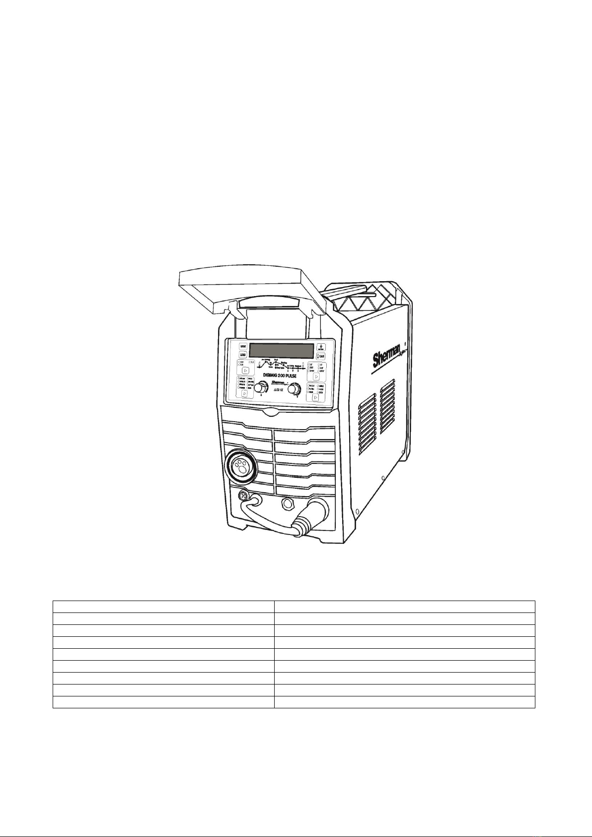
3. GENERAL DESCRIPTION
The synergistic welding machine DIGIMIG 200 PULSE is used for manual welding of steel and non-ferrous metals. It
enables welding with MMA (coated electrode), MMA with pulse, TIG Lift, TIG Lift with pulse, and MIG / MAG. Welding with
the MIIG / MAG method can be carried out with the use of single and double pulse. The MIG / MAG method can be used
in manual and synergic mode, simplifying its operation and allowing the welding machine to be used by people with less
experience and hobbyists. Due to the change of polarity, the device allows welding with the MIG / MAG method using
both standard wires in a protective gas shield and self-shielding flux-cored wires.
The device allows you to connect a Spool Gun (SG) with a mini wire feeder and a D100 spool of steel or colored wire.
The device is made in IGBT technology, which allows for a significant reduction in the weight and dimensions of the welding
machine and an increase in efficiency while reducing energy consumption.
The welder is used in closed or roofed rooms, not exposed to
direct exposure to atmospheric influences.
4. TECHNICAL PARAMETERS
4.1 Welder
Supply voltage:
Maximum power consumption:
Rated welding current: / duty cycle Rated voltage in
no-load condition Wire spool diameters:
Maximum current consumption:
Weight:
Dimensions [mm]:
Level of security:
AC 230V 50Hz
7.7 kVA
MIG: 200A / 60%; MMA: 200A / 60%; TIG: 200A / 60%
56V (9V with VRD)
100mm, 200mm
MIG: 26.5 A; MMA: 33.7 A; TIG: 21.5 A
12 kg
495 x 210 x 345
IP21
4

4.1.1 Adjustment ranges of parameters
Welding current:
Welding voltage:
Wire Feed Speed: Inductance:
Gas pre-flow
Gas post-flow
Pulse frequency
ARC FORCE (MMA):
HOT START (MMA) - electricity:
HOT START (MMA) - time:
MIG: 24 - 200 A; MMA: 20 - 200 A; TIG: 10 - 200 A.
MIG: 17.5 - 24.7 V
2 - 14 m / min
- 99 - + 50%
0 - 10 sec
0.1 - 50 s
TIG, MMA: 0.1 - 99 Hz; D-PULSE MIG: 0.5 - 5 Hz.
0 - 100%
20 - 200 A.
0 - 99 ms
4.2 MIG gun
Handle type:
Maximum current carrying capacity:
Type of cooling:
Cooling gas flow: Length:
TW-15
200 A (CO2)
gas
10-18 l / min
3 m
Work cycle
The duty cycle is based on a 10-minute period. 60% duty cycle means that after 6 minutes of operation, a 4-minute break
is required. Duty cycle of 100% means that the device can work continuously without interruption.
Attention! The heating tests were carried out at the ambient air temperature. The duty cycle at 20ºC has been
determined by simulation.
Level of security
The IP defines the degree to which the device is resistant to the ingress of solid and water contaminants. IP21 means
that the device is adapted to work in closed rooms.
Overheating protection
The IGBT module is protected against overheating by a protective system that turns off the power to the welding
machine. After a few minutes, the device cools down to a temperature that allows it to be switched on again
automatically. Do not disconnect the power supply during this time, because the continuously operating fan cools the
internal heat sinks of the device in order to reduce the temperature faster. After restarting, remember to limit the
welding parameters for further continuous operation of the device.
5. PREPARING THE DEVICE FOR WORK
If the device is stored or transported in frost, bring the device to a temperature above freezing before starting
work.
5

1. MIG gun socket
2. Spool Gun remote control / holder socket
3. "+" socket
4. Polarity reversal plug
5. "-" socket
6. Power switch
7. Fan
8. Shielding gas connection stub
9. Earthing clamp
10. Power cord
11. Spool Gun switch
12. Wire feeder
13. Wire spool pin
6
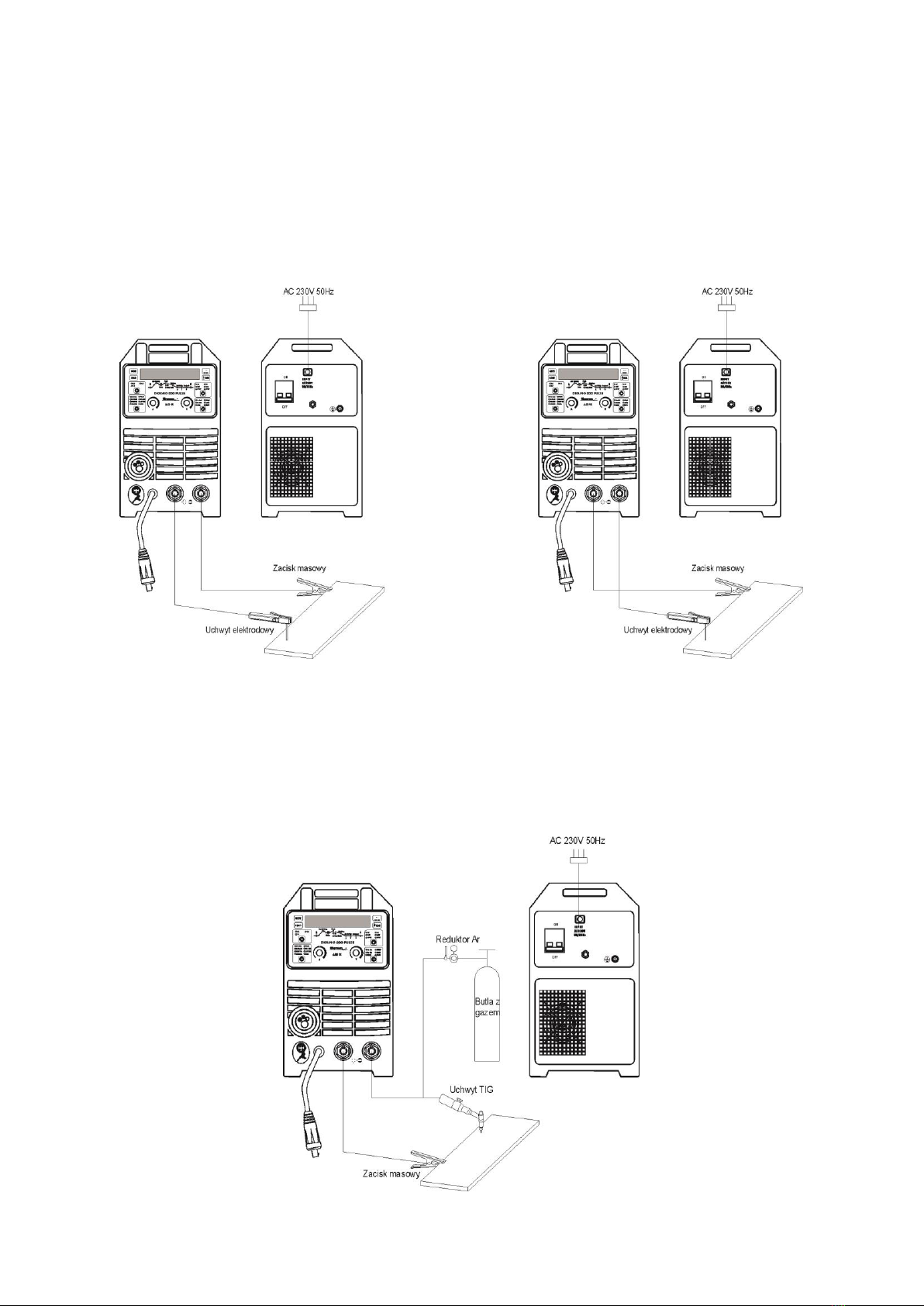
5.1 Connecting the wires
5.1.1 The MMA method
The ends of welding cables should be connected to sockets (3) and (5) on the front panel so that the electrode holder has
the correct pole for the electrode. The polarity of connecting the welding cables depends on the type of electrode used
and is indicated on the package of the electrodes (negative DCEN or positive DCEP). The return line clamp must be
carefully attached to the work piece. Connect the device's plug to a 230V mains socket
50Hz.
DCEN DCEP
5.1.2 TIG method
For welding with this method it is necessary to use an additional TIG torch. A gas-cooled torch with 200A amperage and
a shielding gas control valve is required.
The torch's current clamp should be connected to the negative polarity socket (5), and the gas hose to the regulator on
the gas cylinder. The positive pole of the source (3) should be connected to the work piece by means of a wire with a
clamp. Connect the device plug to a 230V 50Hz mains socket.
7

5.1.3 MIG method and braze welding
5.1.3.1 Welding and braze welding in protective gas shield
The torch current clamp should be connected to the MIG torch socket (1). The gas line from the regulator should be lead
and fastened to the gas connector (8) on the rear wall of the device. Plug the polarity change (4) into the socket (3). The
negative pole of the source (5) should be connected to the work piece by means of a wire with a clamp. Connect the
device plug to a 230V 50Hz mains socket.
5.1.3.2 Welding with self-shielding steel wire
The torch current clamp should be connected to the MIG torch socket (1). Plug the polarity change (4) into the socket (5).
The positive pole of the source (3) should be connected to the work piece with a wire with a clamp. Connect the device
plug to a 230V 50Hz mains socket.
8

5.1.3.3 Welding with Spool Gun (optional)
The torch current clamp should be connected to the MIG torch socket (1). Plug the polarity change (4) into the socket (3).
Connect the negative pole of the source (5) to the work piece with a wire with a clamp. Connect the device plug to a 230V
50Hz mains socket. Set the switch (11) inside the feeder chamber to the Spool Gun position.
5.2 Connecting the shielding gas
1. Attach the cylinder and secure it against falling over.
2. Open the cylinder valve for a moment to remove any contamination.
3. Install the regulator on the cylinder.
4. Connect the hose with the reducer to the gas connector (8) on the rear wall of the welding machine.
5. Unscrew the valve of the cylinder and the regulator.
5.3 Connection to the mains
1. The device should only be used in a single-phase, three-wire system with an earthed neutral
point.
2. The DIGIMIG 200 PULSE inverter rectifier is adapted to work with a 230V50 Hz network protected by 25 A time-
delay fuses. The power supply should be stable, without voltage drops.
3. The device is equipped with a power cord and plug. Before connecting the power supply, make sure that
the power switch (6) is in the OFF position (turned off).
5.4 Loading the wire spool
1. Open the side cover of the housing.
2. Check that the drive rolls are suitable for the wire type and diameter. Install the correct roller if necessary. For
steel wires, use rolls with V-grooves, and for aluminum wires with U-grooves.
3. Place the spool with the filler wire on the spindle.
4. Secure the spool against falling.
5. Release the pressure on the feed rolls.
6. Dull the end of the electrode wire.
7. Introduce the wire through the feeder drive roller into the holder.
8. Press the wire into the grooves of the drive roll.
9. Unscrew the contact tip from the gun, turn on the power supply to the welder and pull the wire into the
welding gun with the quick wire inch function.
10. After the wire appears in the gun outlet, release the button and screw on the contact tip.
11. Adjust the pressing force of the feed roller by turning the pressure knob. Too little pressure force will result in
slippage of the drive roller, too high pressure force will increase the feeding resistance, which may lead to
deformation of the wire and damage to the feeder.
5.5 Preparing the MIG gun to work
Depending on the type of material to be welded and the diameter of the electrode wire, attach a suitable contact tip and
a wire guide to the MIG torch.
When welding steel, use contact tips for welding steel and a steel insert. When welding aluminum, use contact tips for
aluminum welding and a Teflon insert.
5.5.1 Rapid wire inch
The device has the function of a quick wire inch. Pressing the button (B) causes the wire to advance quickly, allowing it to
be easily inserted into the holder.
9
6. SERVICE
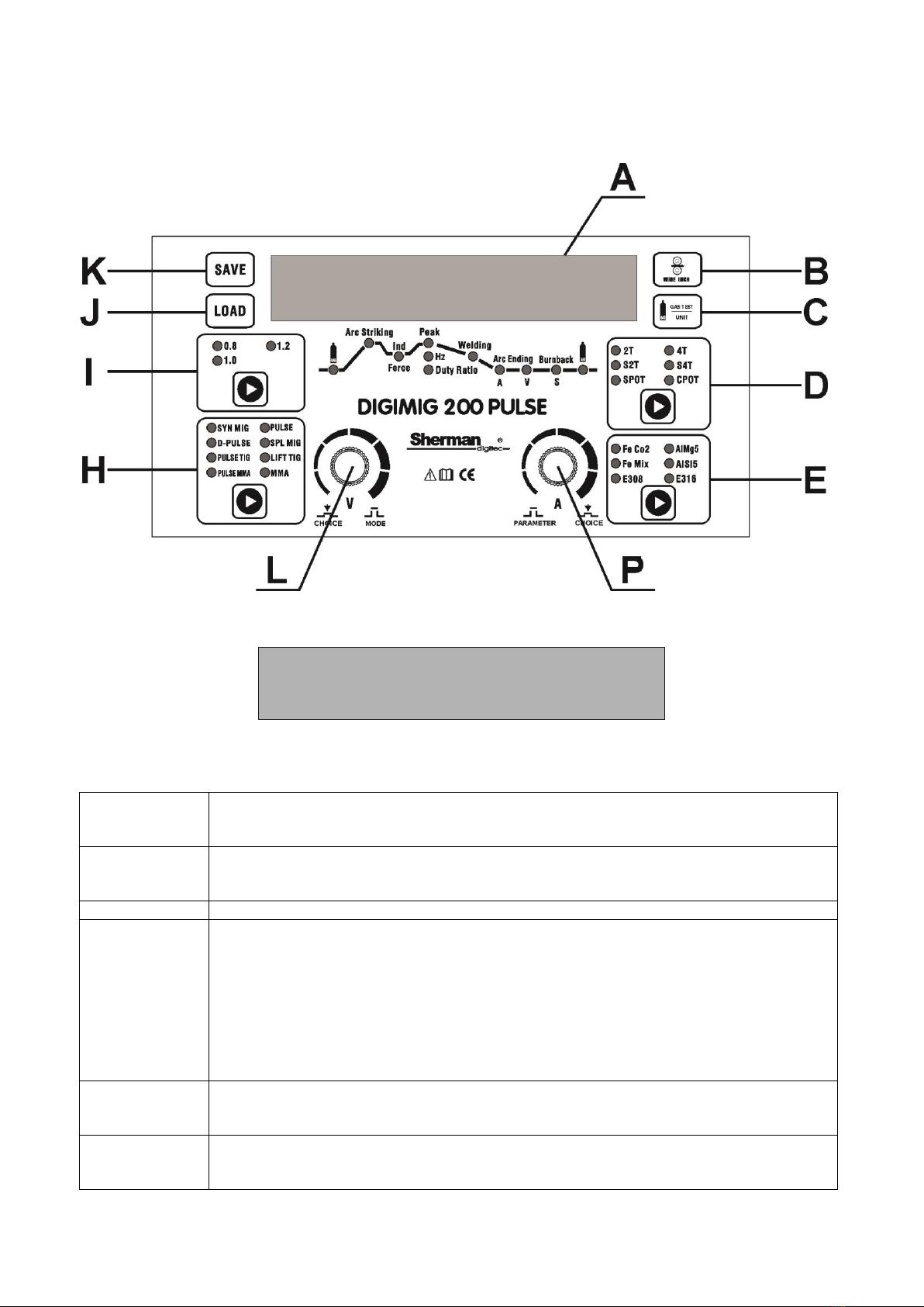
6.1 Front panel
A - Display
The display shows the names and values of the parameters, the numbers of the sets of settings stored in memory, and the
error codes.
The voltage (arc length) of the base current.
Only for the D-PULSE MIG method.
Adjustment range: -50 - 50%.
Burnback - time for which the wire feed continues after the arc has been extinguished.
Adjustment range: -50 - 50% of factory setting. Welding
current
Pulse width - pulse duration, allows you to adjust the depth of penetration. Increasing the
width increases the penetration depth, reducing the amount of heat introduced into the
material, reducing the risk of burning through thinner sheets or smaller components.
Lower pulse width values should be used for higher currents. A larger pulse width should
be used for small currents, for example a width greater than 50% should be used for
currents below 100A.
Only for D-PULSE MIG, PULSE TIG and PULSE MMA methods.
Adjustment range: PULSE TIG, PULSE MMA: 5 - 95%; D-PULSE MIG: 20 - 80%. Final current
(crater filling)
Only for MIG / MAG method in S2T and S4T modes.
The adjustment range depends on the type of material to be welded and the wire
diameter. The duration of the final current (crater filling).
Only for MIG method in S2T mode
Adjustment range: 0 - 50 s
BU
Burn
Cur
Duty
EndI
Endt
10

The final current (crater filling) voltage (arc length). Only for MIG
method in S2T and S4T modes.
Adjustment range: -50 - 50%
ARC FORCE function.
Only for MMA and PULSE MMA methods.
Adjustment range: 0 - 100%.
Pulse frequency.
Only for D-PULSE MIG, PULSE TIG and PULSE MMA methods.
Adjustment range: PULSE TIG, PULSE MMA: 0.1 - 99 Hz; D-PULSE MIG: 0.5 - 5 Hz. HOT START
(MMA) function / starting current (MIG / MAG)
MMA:
HOT START function The HotI parameter is used to regulate the current value by which the
welding current will be increased.
The adjustment range depends on the type of workpiece and the wire diameter.
MIG / MAG:
Initial current.
Only in S2T and S4T modes.
The adjustment range depends on the welding method, type of material to be welded and wire
diameter.
Duration of HOT START (MMA) / starting current time (MIG / MAG)
MMA:
The duration of the HOT START
function. Adjustment range: 0 - 99 ms.
MIG / MAG:
The duration of the starting current.
Only in S2T mode.
Adjustment range: 0 - 50 s.
The voltage (arc length) of the starting current. Only for
MIG / MAG method in S2T and S4T modes. Adjustment
range: -50 - 50%.
Inductance - its adjustment enables optimization of the arc characteristics depending on the
thickness of the welded element as well as the welding method and conditions. Only for MIG / MAG
method.
Adjustment range: -99 - 50%.
Peak current.
Only for D-PULSE MIG, PULSE TIG and PULSE MMA
Adjustment range: MIG / MAG 5 - 50%, PULSE TIG 1 - 500%, PULSE MMA 1 - 50%. Parameter set
number to be loaded.
Gas post flow - the time during which the shielding gas flow continues after the arc has
been extinguished. Only for MIG / MAG method.
Adjustment range: 0.1 - 50 s.
Gas pre-flow - the time it takes for the shielding gas to flow before the arc strikes. Only for
MIG / MAG method.
Adjustment range: 0 - 10 s.
The voltage (arc length) of the peak current.
Only for the D-PULSE MIG method. Adjustment
range: -50 - 50%.
Number of the saved parameter set. Arc
characteristics - constant current mode. For
MMA only.
Arc Characteristics - Constant Power Mode. Used when welding with cellulose
electrodes.
For MMA only.
The duration of the spot welding.
Only for MIG / MAG method in SPOT and CPOT spot welding mode. Adjustment
range: 0.1 - 9.9 s.
Wire feed speed before arc striking. Adjustment range: 1
- 15 m.
Pause time between cyclic strikes of the arc.
Only for MIG / MAG method in CPOT continuous spot welding mode
EndU
FORC
Freq
HotI
Hott
HotU
INDIUM
Ip-p
Load
Post
Preg
PU
Save
Slop CC
Slop CP
Sptt
StFd
Stop
11

Adjustment range: 0.1 - 25.5 s
Thickness of the welded material.
Only for MIG / MAG method in SYN MIG modes. PULSE and D-PULSE. The adjustment
range depends on the type of material to be welded and the wire diameter. VRD
function - reduces the voltage in no-load condition.
For MMA only.
Adjustment range - On (On) / Off (Off).
Tick
VRD
B - Fast wire inch button
Pressing the button causes the electrode wire to advance quickly. It can be used when placing a spool of wire in order to
quickly insert it into the welding holder.
C - Shielding gas button / changing the way of displaying MIG / MAG parameters
GAS TEST
UNIT
The button is active only during MIG.MAG welding
Pressing and holding the button will result in the flow of the shielding gas, its release will stop the gas flow.
In synergic modes, a short press of the button will switch to the current adjustment and welding voltage correction,
and the display will show the welding current (on the right) and information about the percentage of welding voltage
correction in relation to the factory synergic settings.
D - Source operation control button
Button active only in MIG / MAG method. Allows you to select the source operation control mode. The selection of the
appropriate mode is signaled by the lighting of the appropriate diode.
When the gun trigger button is pressed, gas pre-flows, then strikes the arc and starts welding. When the button is
released, the arc will be extinguished and gas will flow out.
12
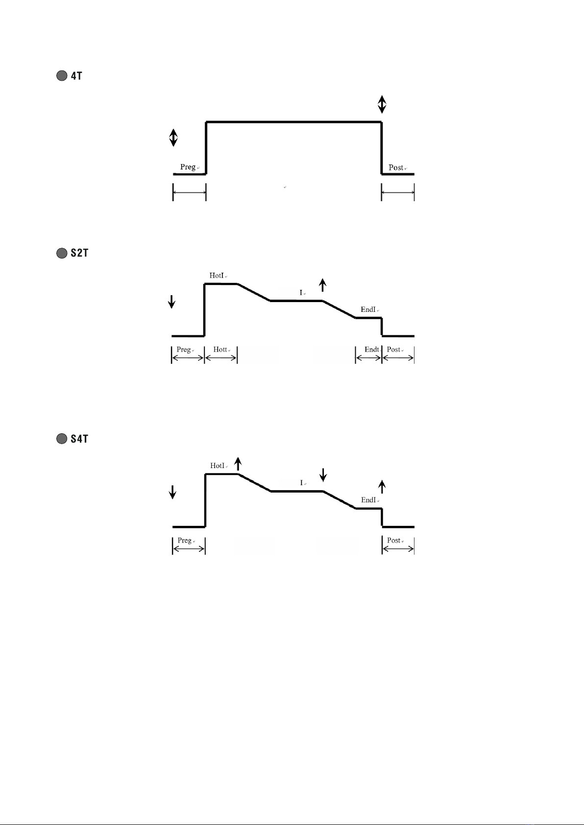
Pressing and releasing the gun trigger button will cause gas to pre-flow, then strike the arc and start welding. When the
button is pressed and released again, the arc will be extinguished and gas will flow out.
When the gun button is pressed, gas pre-flows, then strikes the arc and starts welding with the starting current HotI.
After the HOTt time has elapsed, the welding current value will change to the set value. Releasing the torch button will
change the welding current to EndI, and after the Endt time has elapsed, the arc is extinguished and gas flows out.
When the gun button is pressed, gas pre-flows, then strikes the arc and starts welding with the starting current HotI.
Releasing the button will change the welding current to the set value. Pressing the torch button again will change the
welding current to EndI, and when the button is released, the arc is extinguished and gas flows out.
13
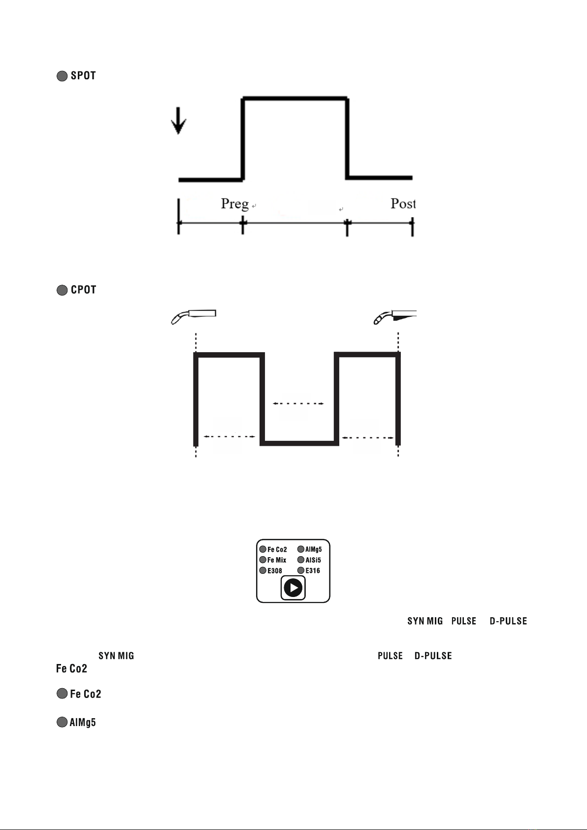
Sptt
Spot welding. Pressing the gun button will cause gas to pre-flow and ignite the arc. After the Sppt time has elapsed, the
arc will be extinguished and gas post-flow will occur. Early release of the torch button will immediately extinguish the
arc and gas post-flow.
Stop
Sptt Sptt
Continuous spot welding. Pressing the gun button will cause gas to pre-flow and ignite the arc. After the Sptt time has
elapsed, the arc will extinguish. After the Stop time has elapsed, the arc will re-ignite and the cycle will continue until
the handle button is released.
arc and gas flow.
E - Workpiece selection button.
The button is active only during MIG / MAG welding in modes
It is used to select the material to be welded. The selection of the appropriate mode is confirmed
, and .
lighting up of the LED
checklist.
In mode All kinds of material are available in modes and is not available
.
-welding of carbon steels in CO shield2.
- welding of magnesium aluminum alloys in an argon shield.
14
-welding of carbon steel in the shield of Ar / CO mixture2. The recommended mixing ratio is 82% Ar
18% CO2.
- argon arc welding of silicon aluminum alloys.
- welding of stainless steel in the shield of Ar / CO mixture2. The recommended mixing ratio is 98%
Ar 2% CO2.
- welding of stainless steel in the shield of Ar / CO mixture2. The recommended mixing ratio is 98%
Ar 2% CO2.
L, P - Control knobs / buttons and parameter graph
DIGIMIG 200 PULSE
CHOICE MODE PARAMETER CHOICE
The (L-left) and (R-right) knobs adjust the parameters welding. Turning the knobs to the left causes
decrease and turn clockwise to increase the parameter value. Pressing the knob (P) saves the currently set parameter
and moves to the next parameter or group of parameters. The currently set parameter or group of parameters is
indicated by the corresponding diode lighting on the parameters diagram. In case of a group of parameters, pressing
the (L) button causes the transition between particular parameters in the group. Knob (P) regulates most of the
parameters, knob (L) can only adjust the welding current during SPL MIG welding or voltage correction during MIG
welding using synergic settings.
H - Welding method selection button
The button is used to select the welding method. The selection of the appropriate mode is confirmed by lighting of the
control diode.
- MIG / MAG welding with the use of synergic settings. The device chooses
welding parameters depending on the selected type and thickness of the material. These parameters can be changed by
the user.
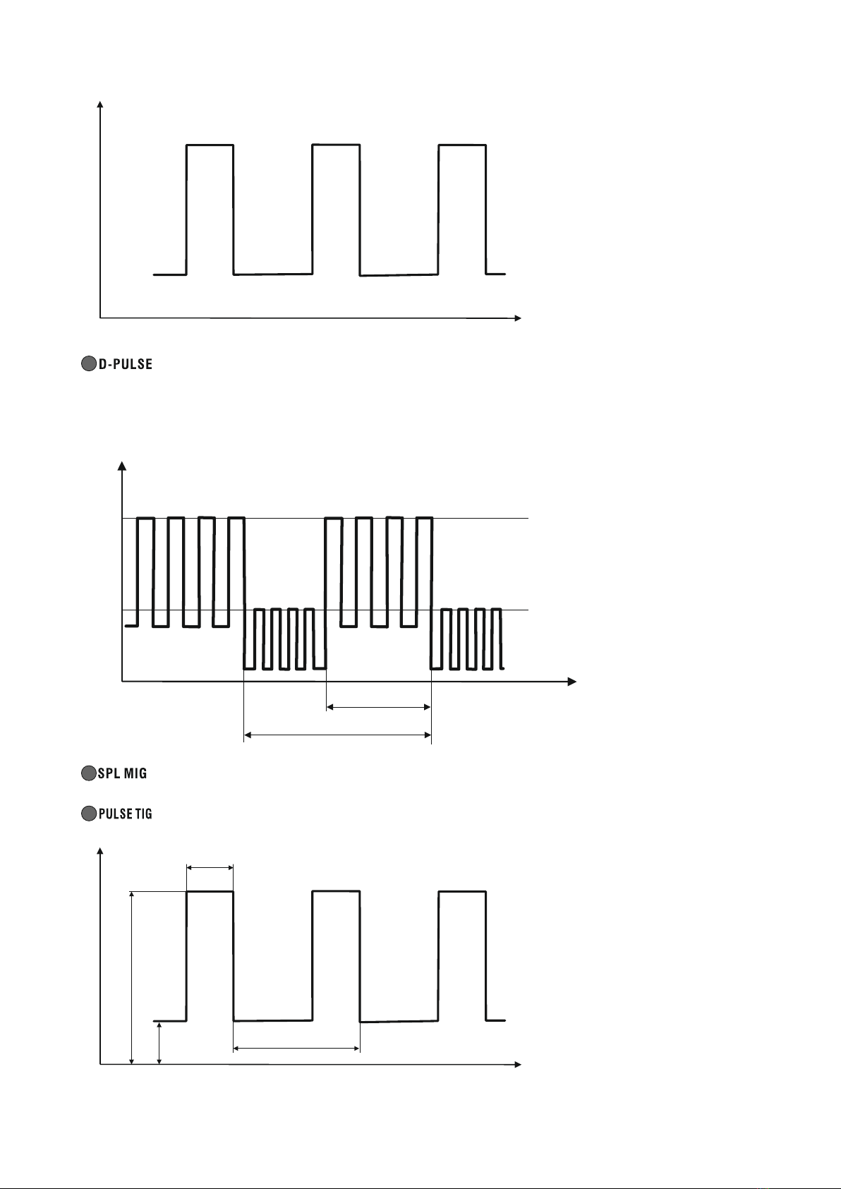
- welding with the MIG / MAG method with pulse. It is an advanced form of welding using
the best form of transfer of the molten material of the electrode wire to the material being welded. Significantly reduces
the formation of spatter and allows welding in all positions. Less heat input eliminates burnout of thin materials. This
method uses synergistic settings.
15
vol
- MIG / MAG welding with double pulse. This is the most advanced
a welding method in which current pulses occur in two ranges. It combines the benefits of welding with a single pulse,
and additionally allows for a very high aesthetics of the weld face
- the so-called scale effect. Welding with this method is very efficient, causes small deformations and
at the same time it allows for a perfect joint appearance. This method uses synergistic settings.
AND
pp
Duty
Freq
- MIG welding with manual settings selection.
- TIG lift welding with pulse.
Duty
Freq
vol
16
Ip-p
Cur
- TIG lift welding.
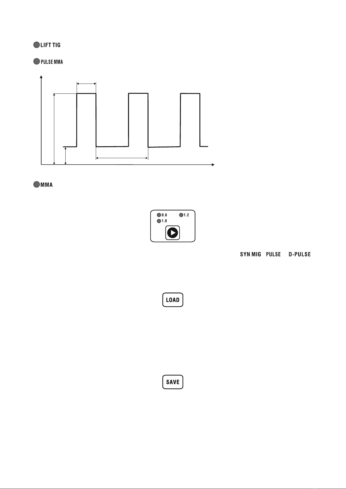
- MMA (coated electrode) welding with pulse.
Duty
Freq
vol
- MMA (coated electrode) welding.
I - Button for selecting the diameter of the electrode wire
The button is active only during MIG / MAG welding in modes , and .
Selects the diameter of the filler wire. The selection of the appropriate mode is confirmed by lighting of the control diode.
J - Settings loading button
The button is used to load sets of parameters previously saved in the device memory. After pressing the button, the
display will show the word LOAD and a flashing number of the parameter set that will be loaded. The set number can be
changed by turning the knob (P). After pressing the knob (P), the message LoadData will appear on the display and the
selected parameter set will be loaded. To exit the settings loading mode and move to parameter adjustment, press the
(L) button.
K - Save settings button
The button is used to save the currently set parameters in the memory. 35 parameter sets can be saved. After
pressing the button, the inscription SAVE will appear on the display and the flashing number of the parameter set
under which the current parameters will be saved. The set number can be changed by turning the knob (P). After
pressing the knob (P), the message SaveData will appear on the display and the current parameters will be saved in
the device memory.
17
Ip-p
Cur

7. PARAMETER SETTINGS
7.1 Method of MMA and PULSE MMA
After selecting the MMA or PULSE MMA method, it is possible to adjust the parameters according to the table below. The
welding current can be adjusted with the adjustment knob immediately after switching the machine on or switching over
welding methods.
MMA PULSE MMA
HotI
Hott
HotI
Hott
Arc Striking Arc Striking
Force Force Force Force
Cur Peak Ip-p
Welding Slop
VRD
Hz Freq
Duty Ratio Duty
Cur
VRD
Welding
VRD function
The VRD function lowers the voltage in no-load condition. The correct voltage is not restored until just before the arc is
struck. This minimizes the risk of electric shock, but in some cases may make the arc difficult to ignite.
ARC FORCE function
The ARC FORCE function allows you to adjust the dynamics of the welding arc. Shortening the arc length is accompanied
by an increase in the welding current, which stabilizes the arc. Decreasing the value gives a soft arc and a smaller fusion
depth, while increasing the value causes deeper penetration and the possibility of short arc welding. With a high value of
the ARC FORCE function, it is possible to weld with the minimum arc length and high electrode melting speed
HOT START function
The HOT START function is popularly called hot start. It works when the arc is struck, causing the welding current to
temporarily increase above the value set by the welder. HOT START is designed to prevent the electrode from sticking to
the material and is a great help when striking the arc. When welding small parts, it is recommended to disable this
function, as it may cause burnout of the welded material.
7.2 LIFT TIG and PULSE TIG method
After selecting the LIFT TIG or PULSE TIG method, it is possible to adjust the parameters according to the table below. Electricity
welding can be adjusted with the welding method
control knob.
immediately after switching on the device or switching it
LIFT TIG PULSE TIG
Welding Cur Peak Ip-p
Serial No. Hz Freq
Duty Ratio Duty
Welding Cur
18

7.3 SYN MIG, PULSE, D-PULSE and SPL MIG method
During MIG welding, the device can operate in synergic (SYN MIG, PULSE, DPULSE) and manual (SPL MIG) modes. The
synergic mode allows less experienced users to choose welding parameters. In this mode, the device automatically
selects the welding current and wire feed speed depending on the type of material to be welded and the diameter of the
electrode wire. It is possible to correct the welding voltage.
Manual mode allows the user to choose the welding voltage and wire feed speed depending on the needs.
Depending on the selected control mode and welding method, adjustments can be made according to the table below.
0.8 / 1.0 1.0 / 1.2 0.8 / 1.0 1.0 / 1.2 0.8 / 1.0 0.8 / 1.0
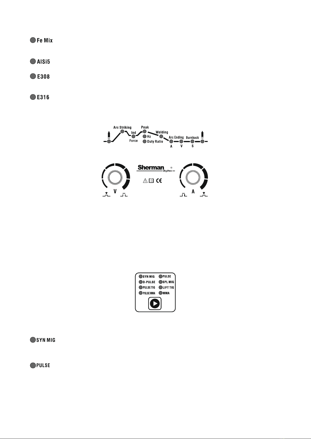
FeCo2 AlMg5 Fe MIX AlSi5 E308 E316
SYN MIG / PULSE / D-PULSE / SPLMIG
Control mode
2T 4T S2T S4T SPOT CPOT
Preg Preg Preg Preg Preg Preg
HotI
Hott
HotU
HotI
HotU
Arc Striking Arc Striking
Indium INDIUM Indium INDIUM Indium INDIUM Indium INDIUM Indium INDIUM Indium INDIUM
Ip-p Ip-p Ip-p Ip-p Ip-p Ip-p
P.Peeaakk P.PUAT
BU
P.Peeaakk P.PUAT
BU
P.Peeaakk P.PUAT
BU
P.Peeaakk P.PUAT
BU
P.Peeaakk P.PUAT
BU
P.Peeaakk P.PUAT
BU
Hz Freq Hz Freq Hz Freq Hz Freq Hz Freq Hz Freq
Duty Ratio Duty Duty Ratio Duty Duty Ratio Duty Duty Ratio Duty Duty Ratio Duty Duty Ratio Duty
U / I U / I U / I U / I U / I U / I
Welding Tick
StFd
Welding Tick
StFd
Welding Tick
StFd
Welding Tick
StFd
Tick
Sptt
StFd
Tick
Sptt
Stop
StFd
Welding
Welding
EndI
Endt
ArcEndingA ArcEndingA EndI
ArcEndingU EndU ArcEndingU EndU
Burnback Burn Burnback Burn Burnback Burn Burnback Burn Burnback Burn Burnback Burn
Post Post Post Post Post Post
Attention! In the SPL MIG mode, it is not possible to select the material to be welded and the wire diameter.
Correction of welding voltage in synergic modes
After setting the welding current in synergic modes, it is possible to correct the welding voltage. After setting the
welding current using the knob (P), you can adjust the welding voltage using the knob
(NS). To check the percentage change in voltage in relation to the value set according to the synergic program, press the
GAS (C) button. By turning the knob (L) it is possible to further correct the voltage. To return to the voltage value display,
press the GAS (C) button again.
Inductance regulation
Adjusting the inductance allows you to optimize the arc characteristics depending on the thickness of the workpiece and
the welding method and conditions. This function is useful during MIG / MAG welding of thin elements, preventing them
from burning out and during brazing of galvanized elements. Changing the inductance value also reduces the amount
of welding spatter during
CO shielded welding2. The greater the inductance value (+), the number of spattering decreases, while the value is
negative (-), the amount of spattering increases. The optimal setting of the inductance value depends
on several factors and may differ from standard recommendations, therefore it should be selected experimentally
during welding tests.
Adjusting this parameter also enables brazing of thin (up to 3 mm) galvanized elements with wires made of CuSi3 copper
alloy in pure argon or in some cases
Ar / CO mixtures2 in the ratio (82/18).
19

Pulse width
The width of the pulse is the duration of the pulse, it allows you to adjust the depth of penetration. Increasing the
width increases the penetration depth, reducing the amount of heat introduced into the material, reducing the risk
of burning through thinner sheets or smaller components.
Lower pulse width values should be used for higher currents. A larger pulse width should be used for small currents,
for example a width greater than 50% should be used for currents below 100A.
The welder has built-in synergic programs for selected materials, wire diameters and gases
shields according to the table below:
Wire -
diameter
Shielding gas -
recommended
Material Designation Type
Fe Co2
Fe Mix
AlMg5
AlSi5
E308
E316
0.8 / 1.0
0.8 / 1.0
1.0 / 1.2
1.0 / 1.2
0.8 / 1.0
0.8 / 1.0
WHAT2
Normal steel Ar + CO2 (82/18)
ArgonER5356
ER4043
ER308LSi
ER316LSi
Aluminum Argon
Ar + CO2 (98/2)
Ar + CO2 (98/2)
stainless steel
High-quality argon should be used: 4.8 and higher recommended
Additionally, depending on the working conditions, you can set the inductance value, which affects the shape of the
weld, the depth of penetration and the number of spattering during welding.. It should be taken into account that the
recommended welding parameters in synergic mode apply to typical welding materials from the selected group
and recommended shielding gases. When welding various alloy materials, the operating parameters may not be
optimal and require adjustment of the settings. For this reason, the synergic mode should not be treated as a
universal parameterization proposal, but as a starting point for fine adjustment of settings.
The manual SPL MIG function, i.e. manual selection of parameters, is especially useful for braze welding. Using the three
welding parameters, set the optimal set to obtain the correct weld. When selecting parameters, choose low voltage
values and high wire feed speeds. It is recommended to use argon as a shielding gas, but gives good results
also using a mixture of argon and CO2 (82/18). Due to the required shape of the weld, the inductance should be selected
experimentally depending on the thickness and type of material to be welded.
Copper-based binders are most often used as an additional material. These are wires marked as CuSi3 or SG –CuAl.
It is recommended to use a handle with a length of no more than 3 m, equipped with a Teflon insert.
8. WELDING OF ALUMINUM ALLOYS
In synergic mode, you can choose between two programs for aluminum welding. The programs were selected for
welding with ALSi5 type ER 4043 wires, mainly intended for foundry aluminum, and with AlMg5 type ER 5356 wire, which
is suitable for welding all types of structures and sections. Welding aluminum is not a simple activity, it requires
experience, knowledge and certain practices from the welder, which will facilitate the execution of welds on aluminum
elements. In the synergic program, the device selects the output parameters for the appropriate material grade and
wire types. Depending on the needs, appropriate voltage and inductance corrections should be made to obtain the
desired effect.
First of all, you should remember about a few important things that significantly affect the appearance of the weld and
have an impact on the correct course of the welding process.
Before starting welding work on aluminum parts, complete the following steps:
Device:
Make sure that the feed rolls are designed to work with aluminum: the groove is U-shaped and dedicated to the
correct diameter of the welding wire. Using the wrong rollers will cause wire deformation and problems in the
welding process.
20
Other manuals for DIGIMIG 2OO PULSE
1
Table of contents
Popular Inverter manuals by other brands


Eaton
Eaton M-Max series user manual

Generac Power Systems
Generac Power Systems 1470-0 owner's manual

AIMS
AIMS PWRINV2.5K24V Assembly and operating instructions

SMA
SMA SUNNY BOY 3000TL Single Tracker installation guide

Samil Power
Samil Power SolarRiver 1100TL Quick instructions

SOLIS
SOLIS S6-EH1P3.8K-H-US user manual