Nibe SOLAR FP215 P User guide

Installer manual
SOLAR FP215 P/PL
IHB GB 1124-1
031968


Table of Contents
1 Important information 2
Symbols 2
Marking 2
Warranty 2
Copyright 2
Contact information 3
2 Delivery and handling 4
Delivery 4
Handling 4
Supplied components 5
3 Installation 7
General 7
Pipe connections 9
4 Mounting 12
General 12
Installing vertical solar panels (P) in horizontal
rows 13
Installing the vertical solar panels (P) on 25° support
stands in horizontal rows 21
Installing horizontal solar panels(PL) in vertical
rows 27
Mounting horizontal solar panels (PL) in a horizontal
row 34
Mounting horizontal solar panels(PL) on 45° support
stands in a horizontal row 35
Mounting inset vertical solar panels (P) 42
Mounting vertical solar panels (P) on adjustable
stands 42-65° 51
Common instructions 57
5 Maintenance 64
Solar panels 64
Freeze prot 64
Control 64
6 Troubleshooting 65
7 Start up protocol 67
8 Maintenance log 69
9 Technical specifications 70
Solar panel dimensions 70
Item register 72
1Table of Contents |SOLAR FP215 P/PL

This manual describes installation and service procedures
for implementation by specialists.
This appliance is not intended for use by persons (includ-
ing children) with reduced physical, sensory or mental
capabilities, or lack of experience and knowledge, unless
they have been given supervision or instruction concern-
ing use of the appliance by a person responsible for their
safety.
Children should be supervised to ensure that they do not
play with the appliance.
Rights to make any design or technical modifications are
reserved.
©NIBE 2011.
Symbols
NOTE
This symbol indicates danger to machine or
person.
Caution
This symbol indicates important information
about what you should observe when maintain-
ing your installation.
TIP
This symbol indicates tips on how to facilitate
using the product.
Marking
SOLAR FP215 P/PL is CE marked and fulfils IP21.
The CE marking means that NIBE ensures that the product
meets all regulations that are placed on it based on relev-
ant EU directives. The CE mark is obligatory for most
products sold in the EU, regardless where they are made.
IP21 means that the product can be touched by hand,
that objects with a diameter larger than or equivalent to
12.5 mm cannot penetrate and cause damage and that
the product is protected against vertically falling drops.
Warranty
The manufacturer's warranty for solar panels applies for
60 months from the date of delivery to the installer.
For solar panel accessories such as pumps, solar energy
controls, expansion tanks, solar energy connection pipes,
roof mountings, solar energy tanks, connectors, valves
etc. the manufacturer's warranty applies for 24 months
from the date of delivery to the installer.
The warranty applies if the installer has filled in and signed
the installation protocol supplied and sent it in to NIBE
in the relevant country within 2 months of the installation
being completed.
The Installation protocol can be sent via e-mail, fax or
letter and the proof of receipt or counterfoil must be
saved. This is then signed by NIBE in the country which
indicates any measures that need to be made by the in-
staller. The signed copy is then sent to the owner of the
system.
The warranty does not apply if the unit has not been in-
stalled correctly, or if there has been carelessness with
the components, or incorrect sizing, or handling faults
or insufficient maintenance, or other fault management
according to common practice.
The warranty does not cover damage in or to the building
or damage to other equipment or property that has been
caused directly or indirectly by faulty solar products. The
warranty does not apply in event of incorrect installation
or handling.
The warranty does not cover damage caused by fire,
water damage, external impact, vandalism or weather
related damage such as excessive snow, storms or thun-
derstorms etc.
NOTE! Warranty faults must be notified within 14 days.
Copyright
The manufacturer retains the copyright for this manual.
These instructions may only be distributed, translated or
copied with the written permission of the manufacturer.
We reserve the right to make changes to the specifica-
tions or illustrations in this manual without prior notifica-
tion.
SOLAR FP215 P/PLChapter 1 | Important information2
1 Important information

Contact information
KNV Energietechnik GmbH, Gahberggasse 11, 4861 SchörflingAT
NIBE Wärmetechnik AG, Winterthurerstrasse 710, CH-8247 FlurlingenCH
Druzstevni zavody Drazice s.r.o, Drazice 69, CZ - 294 71 Benatky nad JizerouCZ
NIBE Systemtechnik GmbH, Am Reiherpfahl 3, 29223 CelleDE
Vølund Varmeteknik A/S, Member of the Nibe Group, Brogårdsvej 7, 6920 VidebækDK
NIBE Energy Systems OY, Juurakkotie 3, 01510 VantaaFI
NIBE Energy Systems Ltd, 3C Broom Business Park, Bridge Way, Chesterfield S41 9QGGB
NIBE Energietechniek B.V., Postbus 2, NL-4797 ZG WILLEMSTAD (NB)NL
ABK AS, Brobekkveien 80, 0582 Oslo, Postadresse: Postboks 64 Vollebekk, 0516 OsloNO
NIBE-BIAWAR Sp. z o. o. Aleja Jana Pawła II 57, 15-703 BIAŁYSTOKPL
© "EVAN" 17, per. Boynovskiy, Nizhny NovgorodRU
NIBE AB Sweden, Box 14, Hannabadsvägen 5, SE-285 21 MarkarydSE
For countries not mention in this list, please contact Nibe
Sweden or check www.nibe.eu for more information.
3Chapter 1 | Important informationSOLAR FP215 P/PL

Delivery
Together with the driver, check the delivery immediately
for the following:
႑Visible damage (compressed packaging etc.)
႑That the correct number of packages have been de-
livered
႑That the solar panels in particular are undamaged.
Handling
It is recommended that straps are used when transporting
solar panels. The solar panel must not be lifted by straps
or the packaging. Avoid shocks and mechanical impact
on the solar panel, particularly on the glass surface, the
pipe connections and the reverse of the panel.
NOTE
Do not lift the solar panels by the packaging or
connectors. Do not place the solar panels on
objects that can damage them, nor pull or drag
them over anything that can damage them.
SOLAR FP215 P/PLChapter 2 | Delivery and handling4
2 Delivery and handling

Supplied components
Varies depending on the type of roof installation config-
uration that has been ordered.
SOLAR FP215 P/PL for mounting on roofs
Profile hookJoint kitMounting rail
Wing nut M10Fixing wedge, ex-
ternal
Fixing wedge,
middle
Screw M10x25Washer 10.5Self locking nut
M10
SOLAR FP215 P for installation on flat / low
pitch roofs
Support stand 25°
SOLAR FP215 PL for installation on flat / low
pitch roofs
Support stand 45°
SOLAR FP215 P/P for installation on ad-
justable stands on ground foundation /
bitumen roofs
External locking
clamp
Rail, stand
Angle jointUpper Centre lock-
ing clamp
Lower Centre lock-
ing clamp
Screw M10x65Screw M10x25Screw M10x10
Washer 10.5Spacer 10.5x20x5Nut M10
Spring washer
B10.2
5Chapter 2 | Delivery and handlingSOLAR FP215 P/PL

Underlying roof securing components
LEK
LEK
LEK
AdapterUniversal fixing plate and bolt
kit
Coach boltTile roof bracket
LEK
Raised sealing plateStanding seam holder
LEK
Bolt kit general
SOLAR FP215 P for installation on roofs
SMP-ID1 Expansion kit for
each subsequent solar
panel
SMP-ID2 Basic kit for two
solar panels
Contents:Contents:
1 x right upper piece
1 x lower piece
1 x lead panel
1 x intermediate panel
1 x upper intermediate pan-
el
1 x left side piece
1 x right side piece
1 x right upper piece
1 x left upper piece
1 x right lower piece
1 x left lower piece
1 x left lead panel
1 x right lead panel
1 x intermediate panel
1 x upper intermediate pan-
el
Small components:Small components:
2 x solar panel hooks
2 x fixing wedges, centre
9 x Torx screws M6 x 40
6 x nails
1 x panel screw 4.5 x 35
2 x foam strips
4 x solar panel hooks
4 x fixing wedges, external
2 x fixing wedges, centre
17 x Torx screws M6 x 40
12 x nails
3 x panel screws
1 x panel screw 4.5 x 35
2 x foam strips
20 x clamps
SOLAR FP215 P/PLChapter 2 | Delivery and handling6

General
The installation must only be carried out by competent
personnel.
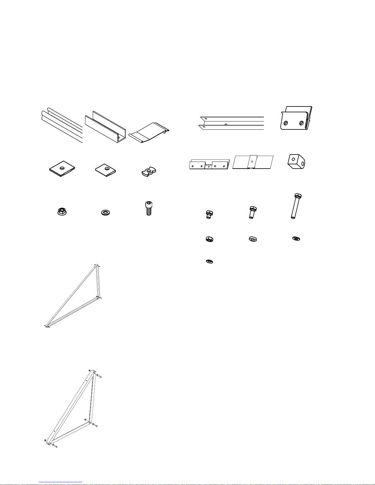
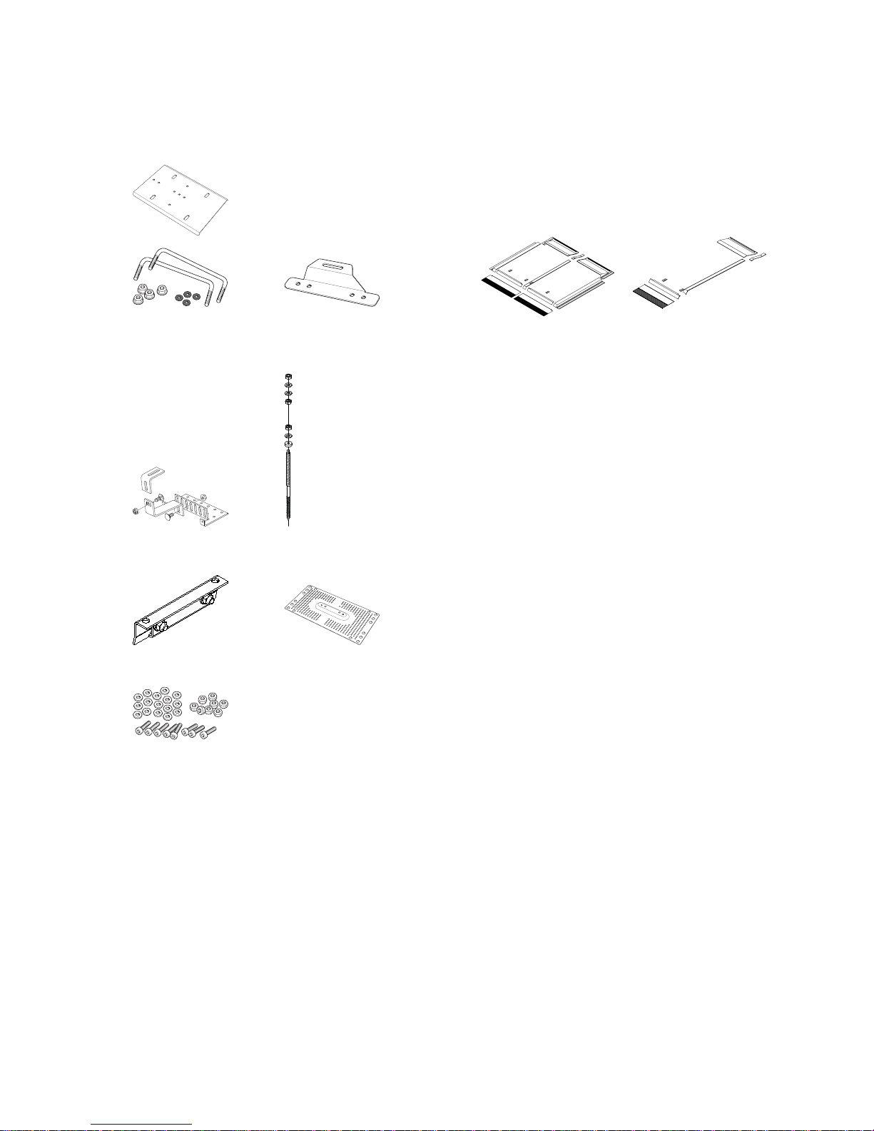
The supplied material is the minimum that is required for
use with normal installations, in special cases it may need
to be supplemented. If unsure contact the supplier. Before
the installation and commissioning of the solar panel
system, information must be obtained on the applicable
norms and regulations.
NOTE
Installation of a solar panel is an extensive inter-
vention on an existing roof. The roof covering,
especially tiles, roof panels or slates - particularly
on converted and inhabited loft spaces or where
the roof's minimum angle is below size (relative
to the covering) - requires further measures
against moisture because of wind pressure and
drifting snow, this must be evaluated by the in-
staller on a case to case basis. The roof design
must be able to handle the wind and snow
loading that can occur in the region.
Static load
The installation may only be carried out on roof surfaces
or support constructions with sufficient carrying capacity
and durability. The static load capacity of the roof and
roof construction must if necessary be examined before
the solar panels are installed. Great weight should be
placed on the condition of wood roof constructions and
the possibility of screwing the mounting devices for the
solar panels into the construction. The roof construction
must be reinforced if necessary. Inspection of the whole
solar panel installation in accordance with DIN 1055 parts
4 and 5, or in accordance with country specific regulations
is particularly required in areas with snow fall and strong
winds. The characteristics of the installation's location
(prevailing wind direction, whirl winds etc.) must also be
included in the calculation/evaluation of whether these
could mean increased loads. The solar panel must be in-
stalled so that snow drifts from snow guards or because
of special conditions in the installation location cannot
occur in the vicinity of the solar panels.
The distance from the outer edges of the roof must be
at least1mtominimise the risk of wind tearing the solar
panel loose.
The installation system according to DIN 1055 part 5 for
snow zone II is intended for use up to 400 m above sea
level. We recommend that sheet metal roofs are used
instead of tiles, which can break more easily and/or the
number of brackets are increased at snow loads above
0.75 kN/m² or wind loads exceeding 0.5 kN/m². Sheet
metal roofs are always better at resisting snow and wind
loads which is why these are primarily recommended.
Stone tiles and slabs can crack more easily from the
stresses that occur. If the installation is made on a tiled
roof it is recommended that the snow is cleared if it
reaches a depth of more than 30 cm on the solar panels.
In certain cases the snow can be melted using the force
operation with the circulation pump in the solar circuit.
In roofs other than tiled a depth of 40 cm is acceptable
before the snow must be cleared. (NOTE! If the snow has
melted, packed down and then more snow has fallen
and so the density has increased, the snow may need to
be cleared despite the fact that it is not 30 cm or 40 cm
deep.)
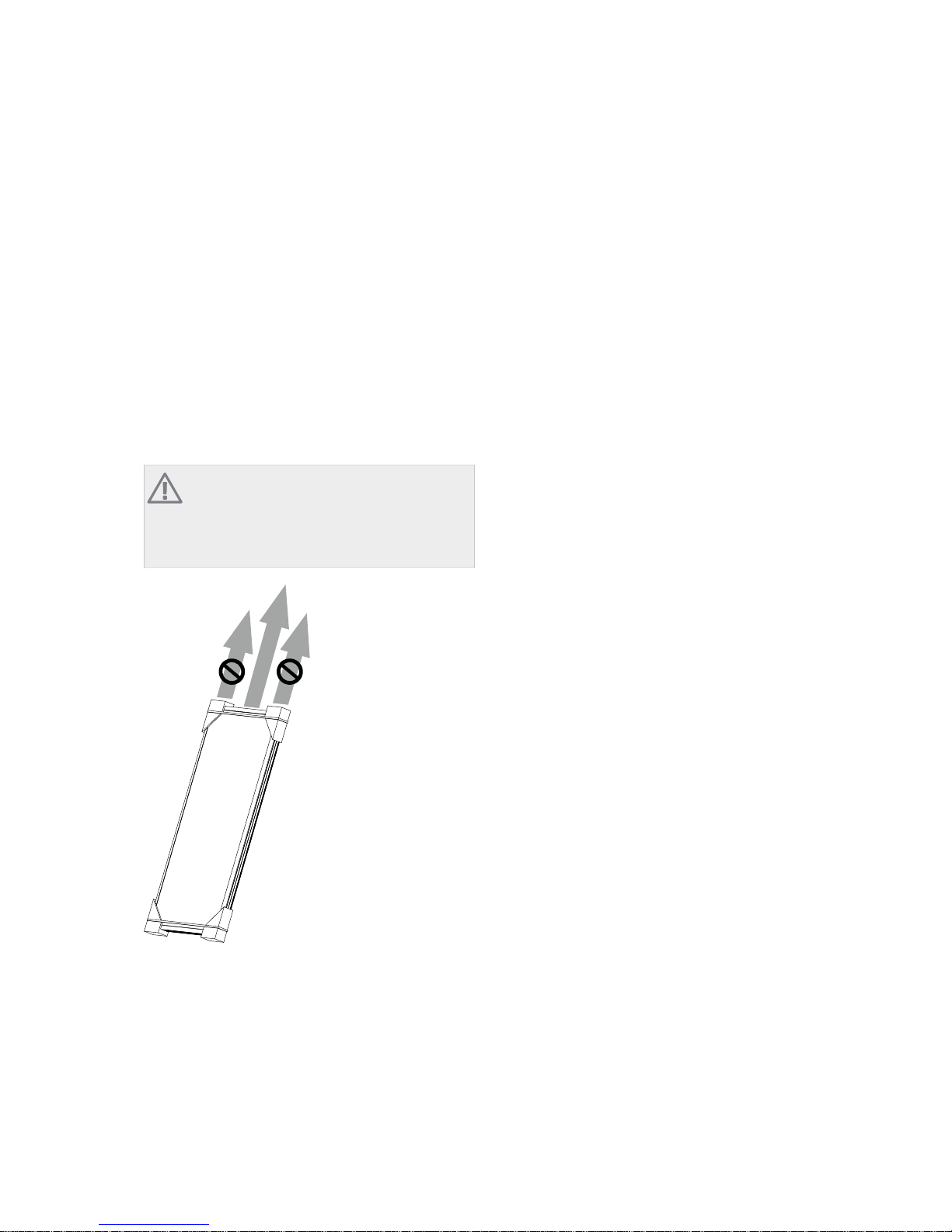
If there is a risk that the snow will slide down onto the
panels and in particular behind the rear of raised panels,
snow guards must be installed to prevent this.
Ensure that the material under the stone roof is suffi-
ciently stable to accept the roof mounting points. Other-
wise the roof must be reinforced. The installer must
evaluate this and make a decision, if uncertain a structural
engineer should be consulted. We recommend that the
tiles are cut down so that there are no spot loads between
the roof and the brackets. The minimum distance
between stone roofs at overlap points and the underside
of the brackets is 3 mm, this is in order to allow for the
movements in the mountings system in reaction to the
loads that occur.
Lightning protection/potential compensation
Principle: Because copper or steel pipes from the solar
panel are connected to the solar pump and storage unit,
electrical current could reach the electronic components.
Damage from lightning strikes is very rare, in practice
systems rarely have lightning protection.
The requirement for lightning protection is stated in DIN
EN 62305 (VDE 0185-305) 2006-10. The requirements
for grounding are defined in DIN 18104:2007-09.
Internal lightning protection
Both direct lightning strikes and current spikes can dam-
age the electronics in the control system. Therefore the
constituent metal pipes and storage tank can be connec-
ted to a varistor. This internal lightning protection in
conjunction with an external earth gives the installation
a secure lightning protection.
External lightning protection
Technical systems on the building roof (for example solar
panels, ventilation or parabolic antennas) must be protec-
ted by external lightning protection systems. The solar
panels and the roof constructions must be integrated so
that the solar panel field is protected from a direct light-
ning strike. The combined solar panel area must be loc-
ated within the protective area provided by the lightning
protection. A safety distance of 0.5 m in all directions
7Chapter 3 | InstallationSOLAR FP215 P/PL
3 Installation

from the solar panel to the periphery of the protected
area must be observed.
Solar panel angle/general
The solar panel can be angled between 20° and 70°. If
the installation is to have a steeper inclination than 70°,
extra measures are required to prevent rain from entering
the solar panel’s ventilation holes at the solar panel’s
upper edge. The protection must be designed so that the
solar panel’s ventilation still functions, for example a
protective panel of a suitable shape.
Bear in mind that on steeper pitches and in particular
high facades, it is extra important to install snow guards
and to also further secure the mountings for the solar
panels.
Venting / flushing and filling
If the solar panel is not to be commissioned immediately
the protective foil should not be removed. It should re-
main on the solar panel until the solar panel is started. It
protects the seals and the heating medium fluid against
overheating. Protective foil or coverage of the solar panel
needs to be managed in the event of draining the solar
circuit or long term stand still of the empty system.
Damage due to overheating is not covered by the manu-
facturer’s warranty.
Caution
Faulty dimensioning or system shut down for periods with
high solar radiation can lead to overheating and steam
build up in the system. Heating medium and sealing ma-
terials can be damaged during repeated or long term
overheating. In the event of risk of long term or frequently
occurring stagnation / vaporisation in the solar panels, it
is recommended that adequate cooling or heat dissipation
is installed.
Check that the glycol/water mixture that is used has the
right characteristics for lowest anticipated temperature
on the installation place.
Glycol should be checked every other year and filled as
necessary. The glycol mixture pH value must be higher
than 7. The medium must be replaced if discoloured
brown, cloudy or smells bad.
The manufacturer/supplier cannot accept any responsib-
ility for any frost damage.
Installation of sensors
The temperature sensor must be installed in the hottest
solar panel submerged tube. To give maximum contact,
the gap between the submerged tube and the sensor
must be filled with suitable heat conducting paste such
as silicone grease with heat tolerance up to approx.
210 C. Good temperature tolerance also applies to insu-
lation, cables and other items that can be exposed to
high temperatures.
To prevent damage caused by rodents or birds a bite
resistant sock can be threaded over the sensor cable and
insulation.
Operating pressure
The maximum operation pressure is 0.6 MPa (6 bar).
Maintenance of the solar panel
The solar heating system must be visually checked regu-
larly with regard to diverse damage, leakage; the inspec-
tion and date must be documented in the maintenance
schedule.
For further information about maintenance, see page 64.
SOLAR FP215 P/PLChapter 3 | Installation8

Safety instructions
႑Applicable safety regulations for working on roofs
and similar constructions must be followed.
႑Barriers to protect against falling parts must be in-
stalled. This is particularly important for high buildings
and locations where a lot of people pass below the
roof/under the building.
႑Personal safety equipment or scaffolding must be
used when working on roofs, according to the applic-
able.regulations.
႑Adequate measures must be taken during the install-
ation so that the solar panel does not come loose and
fall.
႑Do not fill the unit in strong sunlight. There is a risk
of injury from steam.
႑If necessary, cover the solar panels and/or wait until
after sunset.
႑Never fill the unit with water and never pressure test
it when there is a risk of frost.
႑Observe the safety distance to the current conducting
cables.
Pipe connections
General
Pipe routing
Plan pipe routing before you start the installation of pipes
and make any holes in walls and roofs (consider the dur-
ability). Ducts and chimney flues that are not used can
be used to route lines from the solar circuit on the roof
to solar tank. If an unused chimney flue is used, the
chimney sweep must be informed of this in advance.
If the solar circuit pipes are routed outdoors, they must
be protected against wind and rain. Consider the UV
resistance when calculating the insulation.
Because the frost protection is used in the solar panel,
and because the system can become very warm, several
points must be observed. In principle two materials can
be used for pipe-routing: copper pipes or stainless steel.
Copper pipes can be connected with high quality Vatette
type compression ring couplings, always use support
sleeves with Vatette compression ring couplings (for extra
safety apply high temp thread adhesive to the compres-
sion rings), press couplings with suitable high temperature
O-rings, or hard soldered. Stainless steel flexible pipes
must be installed with the couplings provided.
Suitable Teflon tape or high temperature thread adhesive
(at least 230 °C) can be used in any thread connections
in the solar circuit. However, linen or hemp are unsuitable
for use in solar circuits.
Venting
The solar circuit must be completely filled with a mixture
of glycol and water at the highest point.
It must be possible to bleed the solar panel system prop-
erly, avoid air bubbles as far as possible. Normally air
bubbles can be flushed during the filling process. If vents
require fitting only use manual vents, never automatic.
Bear in mind that any venting devices must be able to
tolerate high temperatures.
In larger systems with several rows the vents must be in-
stalled at the end of each row, at the solar panels’s ad-
vance. Suitably plugged with a high temperature tolerant
ball valve or a compression ring T-pipe with compression
plug that is used at any supplementary "seeping" which
may be necessary after running the system with a "filling
barrel" / solar filling station. The direction of flow must
be considered here.
NOTE
Professional filling equipment must be equipped
with a dirt filter in such a way that the system
is cleaned during filling and the venting process.
9Chapter 3 | InstallationSOLAR FP215 P/PL

Miscellaneous
The solar panel must be designed as a closed system,
because the inhibitors in the antifreeze are quickly con-
sumed by penetrating atmospheric oxygen.
The system must not be equipped with a galvanised heat
exchanger, heat accumulators, tanks or pipes, because
zinc can be replaced by 1,2-propylene glycol.
It is important that all sealing and binding materials are
heat tolerant to the maximum stagnation temperature
that can occur in the solar power system.
No external electrical potentials may occur between the
components in the system that are in contact with the
anti-freeze. On the other hand a limited external potential
(around 1.5 volt) can occur in copper system components.
The system and its components must be protected against
penetrating dirt and water during installation and before
filling.
Starting
Fill in the commissioning protocol on page 67 in conjunc-
tion with commissioning.
Insulation
The pipes must be insulated to minimise heat losses.
Insulate the pipes according to national norms and prac-
tice.
A very high heat tolerance must be guaranteed for pipes
and pipe insulation in the solar circuit, because temperat-
ures of up to 200 C can occur in the circuit. Appropriate
insulation must therefore be used in the solar circuit.
Pressure drop diagram
Pressure drop diagram for water:
Pressure loss
in mbar
0
20
40
60
80
100
120
140
160
180
0 20 40 60 80 100 120 140 160 180 Flow rate
in kg/h
3UHVVXUH
GURS LQ
PEDU
)ORZ LQ
NJK
With glycol mix heating medium the relevant correction
parameters must be observed.
If Tyforop L is used with 44 % glycol, the following
pressure drop curve applies:
Pressure loss
in mbar
0
20
40
60
80
100
120
140
160
180
200
0 20 40 60 80 100 120 140 160 180
Flowrate
in kg/h
3UHVVXUH
GURS LQ
PEDU
)ORZ LQ
NJK
Pipe connection option
In general, the connection of the individual rows in larger
solar heating systems should be according to the Tichel-
mann principle. With several rows, the return connection
between the junction and solar panel must be equipped
with a ball valve or adjustment valve with high heat toler-
ance. This must be insulated after commissioning. But it
must be marked to show that there is a possible shut off
valve under the insulation! This is in order to be able to
vent row by row and to adjust the flow if necessary.
NOTE
The solar panel’s safety valve must never be able
to be switched off from the solar panel.
Recommended flow:
Min flow: 0.35 minute litres / m2
Max flow: 0.75 minute litres / m2
Parallel two sided connection of vertical solar
panels
Advance
Return
6XSSO\
5HWXUQ
Parallel single sided connection of vertical solar
panels
Return
Advance
6XSSO\
5HWXUQ
SOLAR FP215 P/PLChapter 3 | Installation10

Parallel two sided connection of horizontal solar
panels
Return
Advance
6XSSO\
5HWXUQ
Parallel single sided connection of horizontal
solar panels
Advance
Return
5HWXUQ
6XSSO\
Dimensioning of pipes with 6 m standard pump
Max number of solar
panels
Pipe dimensions
7 (two sided connection)10-15 m x16mm
6 (two sided connection)20-25 m x16mm
6 (single sided connection)10-15 m x16mm
5 (single sided connection)20-25 m x16mm
8 (two sided connection)10-15 m x20mm
7 (two sided connection)20-25 m x20mm
7 (single sided connection)10-15 m x20mm
6 (single sided connection)20-25 m x20mm
Dimensioning of pipes with 8 m pump
Max number of solar
panels
Pipe dimensions
8 (two sided connection)10-15 m x16mm
7 (two sided connection)20-25 m x16mm
7 (single sided connection)10-15 m x16mm
6 (single sided connection)20-25 m x16mm
12 (two sided connection)10-15 m x20mm
10 (two sided connection)20-25 m x20mm
9 (single sided connection)10-15 m x20mm
8 (single sided connection)20-25 m x20mm
Recommended pre-pressure in solar expansion tank & system pres-
sure in solar circuit
2.5 Bar for a low building,
single story house type (5 m
between tank and solar
panel)
Initial pressure
NOTE! Check before filling
the system!
3.0 Bar for a taller building
(10 m)
3.0 Bar (5 m)Operating pressure
3.5 Bar (10 m)NOTE! With cold piping!
11Chapter 3 | InstallationSOLAR FP215 P/PL

General
SOLAR FP215 P/PL available in 2 versions:
႑NIBE Solar FP215P (Vertical solar panel)
႑NIBE Solar FP215PL (Horizontal solar panel)
Roof mounting components are available in 3 basic vari-
ants with sub-variants:
1. Mounting on roof:
႑Tiled roof, horizontal rows (P), page 13
႑Tiled roof, vertical rows (PL), page 27
႑Tiled roof, horizontal rows and 25° stand (P), page
21
႑Tiled roof, horizontal rows and 45°stand (PL),
page 35
႑Corrugated iron roof, horizontal rows (P / PL),
page 13
႑Corrugated iron roof, vertical rows (PL), page 27
႑Corrugated iron roof, horizontal rows and
25°stand (P), page 21
႑Corrugated iron roof, horizontal rows and
45°stand (PL), page 35
႑Seamed sheet metal roof (P), page 13
႑Seamed sheet metal roof, vertical rows (PL), page
27
႑Seamed sheet metal roof and 25° stand (P), page
21
႑Seamed sheet metal roof and 45° stand (PL), page
35
႑Bitumen roof, horizontal rows (P / PL), page 13
႑Bitumen roof, horizontal rows (PL), page 34
႑Bitumen roof, horizontal rows and 25°stand (P),
page 21
႑Bitumen roof, horizontal rows and 45°stand (PL),
page 35
႑Bitumen roof, horizontal rows and adjustable
stand 42-65° (P), page 51
႑Coach bolt (universal), horizontal rows (P), page
13
႑Coach bolt (universal), horizontal rows and
25°stand (P), page 21
႑Coach bolt (universal), horizontal rows and
45°stand (PL), page 35
2. Inset installation:
႑Certain tiled roofs (P), page 42
3. Mounted on adjustable stands on bitumen roof or
on ground/concrete foundation
႑Adjustable stand 42-65° (P), page 51
SOLAR FP215 P/PLChapter 4 | Mounting12
4 Mounting

Installing vertical solar panels (P) in horizontal rows
The different installation variants that are covered here are:
႑Tiled roof, horizontal rows (P)
႑Corrugated metal roof, horizontal rows (P)
႑Seamed sheet metal roof (P)
႑Bitumen roof, horizontal rows (P)
႑Coach bolt (universal), horizontal rows (P)
The principle shown is installation on a tiled roof.
Overview
The stand can be installed on a number of different roof types,
the image beside illustrates when the panels and mounting
rails are installed on mounting components for tiled roofs (tiled
roof brackets).
How the different mountings should be installed is described
in Roof mountings on page 57.
A joint kit for mounting rails is always required if several
mounting kits are to be combined.
The brackets must be adjusted for the roof according to the
local conditions.
13Chapter 4 | MountingSOLAR FP215 P/PL

5HIHUHQFH SRLQW
1. Mark out the solar panels intended location and
mounting points
Mark the desired position on the roof using chalk before you
install the solar panels. The reference point is the mounting
for the mounting rail on the bracket.
SOLAR FP215 P/PLChapter 4 | Mounting14

A A
B
C
B
C
B
C
B
C
D
D
D
E
E
F
F
F
If there is not a sufficiently stable substructure such as tongue
and groove or trusses to allow a durable installation the roof
must be reinforced.
NOTE
The minimum number of mounting points only cover
a part of the potential wind and snow load.
Mounting points are adapted to the local conditions.
The distance between the solar panels is 24 mm.
The brackets are always positioned where the roof tile is low-
est.
Size:
A: 150 mm
B: min. 170 m m
C: 150 mm
D: max. 500 mm
E: 540 mm
F: 200 mm
2. Joining rails
If several mounting rails are used each rail must be locked with
the appropriate joint kit before mounting to the brackets.
The mounting rails are locked to each other with 1 joint kit,
2 screws M10 x 25, 2 washers and 2 self locking nuts.
15Chapter 4 | MountingSOLAR FP215 P/PL

3. Installing the mounting rails
The mounting rails are screwed into place in the different types
of roof mounting, the following is an example of how the
mounting rail is secured into the different alternatives.
(a1) Mounting rails on the tiled roof bracket (tiled roof)
Mounting rails are secured in the brackets with screws
M10 x 25, washer and self locking nut.
Also see Mounting on tiled roofs on page 57.
NOTE
There must be at least 3 mm between the underside
of the bracket and the lower tile at the overlap point.
(a2) Adjusting the height of the rail
The rails must be adjusted for the local conditions as illustrated.
(b) Mounting rail on standing seam holder (seamed sheet
metal roof)
The mounting rails are secured in the roof mountings with
screws M10 x 25, washer and nut.
Also see Mounting for double seamed sheet metal roofs on
page 58.
SOLAR FP215 P/PLChapter 4 | Mounting16

(c) Mounting rails on raised sealing plate (bitumen roofs)
The mounting rails are secured in the roof mountings with
M10 bolts and a rubber gasket between the raised sealing
plate and the adapter.
Also see Mounting raised sealing plate (bitumen roof) on page
60.
(d) Mounting rails on universal fixing plate (corrugated
metal roof)
The mounting rails are secured in the roof mountings with
screws M10 x 25, washer and self locking nut.
Also see Universal fixing plate for corrugated metal roof on
page 59.
(e) Mounting rails on coach bolts (universal plus slate
roofs)
Correct conditions are required for this variant.
The mounting rails are set on pin bolts that are fixed wit the
upper and lower nuts, the arrow indicates where the mounting
rail should be.
Caution
The coach bolt should only be used if the base it is
to be screwed into is substantial and strong. This
must be established by the installation company.
The installer must evaluate if the moisture protection is suffi-
ciently secure, this is based on factors such as roof pitch in
relation to the rubber seal’s position against the roof base,
the smoothness of the roof base also has an impact.
Also see Universal fixing with coach bolt on page 62.
17Chapter 4 | MountingSOLAR FP215 P/PL

4. Profile hooks
The profile hooks must be positioned so that each solar panel
is held by 2 profile hooks.
5. Install the first solar panel
NOTE
Before the first solar panel is aligned, check that all
the mounting components are tightened and that
the roof is sealed.
The solar panel must always be positioned with the sub-
merged tube for the temperature sensor upwards. Check
that the solar panel locates in both profile hooks during
alignment. Then remove the corner protection.
6. Secure the first solar panel
Secure the outer side with a screw M10 x 25, washer, external
fixing wedge and wing nut in the respective mounting rail.
The nut wings must lock in the mounting rail. The fixing wedge
teeth must lock in the solar panel profile.
Install the centre fixing wedge with M10 x 25 Allen screw,
washer and wing nut. Do not tighten!
SOLAR FP215 P/PLChapter 4 | Mounting18
This manual suits for next models
1
Table of contents
Other Nibe Inverter manuals
Popular Inverter manuals by other brands

Audiovox
Audiovox ADC350 owner's manual

THOR
THOR PPI Series instruction manual

Fischer Panda
Fischer Panda AGT 4000 PVMV-N Handbook

Fuji Electric
Fuji Electric FRENIC-Lift LM2A Series instruction manual

Vector
Vector VEC061 Owner's manual & warranty

Fuji Electric
Fuji Electric FRENIC-Multi Series instruction manual