Shibuya Hoppmann L500A V2 Instruction Manual

TM
L500A V2 High
Speed Labeler
Installation/Maintenance
Manual
Publication Version, Revision 1, All rights reserved.
© 2011 Shibuya Hoppmann Corporation
13129 Airpark Drive, Suite 120 • Elkwood, Virginia 22718 • USA
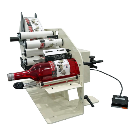
Tel: (540) 829-2564 • Fax: (540) 829-1726 • E-mail: [email protected]
Duplication of this manual, in whole or in part, requires written consent of Shibuya Hoppmann Corporation.
Model Name: Model Inventory Number:
Refer all servicing to qualied personnel.
This manual is intended for use by qualied
mechanic and electricians who install or service
the L500A V2 High Speed Labeler.
Please copy this information from
the L500A V2 High Speed Labeler’s
serial plate.

L500A V2 High Speed Labeler Manual
2 3
About This Manual
Who Should Read
This manual is intended for those who need to install and/or operate the
label applicator. The manual is not intended to meet the training needs of
persons new to labeling; nor is it intended to meet the needs of person‑
nel who wish to completely overhaul the unit. These needs will require
assistance of experienced personnel and are outside the scope of this
manual.
Note:
Please carefully read this entire manual before operating your label ap‑
plicator.
Caution Symbols
Caution symbols and messages in this manual call attention to
and Messages
hazardous voltages, moving parts, and other hazardous conditions.
The exclamation point caution symbol denotes possible personal injury
and/or damage to the equipment.
The lightning bolt caution symbol denotes possible personal injury and/
or damage to the equipment from electrical hazards.
Quick Start
Equipment Improvements & Shibuya Hoppmann Corporation (SHC) continually improves its products, and reserves the right to change
DocumentRevisionsNotice ordiscontinuespecicationsanddesignsshowninthismanualwithoutnoticeandwithoutincurringobligation.
SHC has made every effort to verify the information contained in this manual, but reserves the right to correct
any error at the time of the manual’s next revision. This manual is subject to change without notice. 02/11

2 3
Quick Start
2 About This Manual
3 Table of Contents
6 TermsandDenitions
Description and
7 The Label Applicator
Specications
11 ApplicatorSpecications
Figures/Tables:
8 Figure 1‑1. Label Applicator
9 Figure 1‑2. Side View of L500A V2 Labeler
10 Figure 1‑3. Back View of L500A V2 Labeler
11 Table1‑1.ApplicatorSpecications
Safety Precautions
13 Warnings and Conditions
Figures:
13 Figure 2‑1. Additional Warning Labels
Applicator Installation
15 Unpacking and Inspection
15 Applicator Positioning
20 Remote Electrical Enclosure/Interface Panel
21 Power Supply
Figures/Tables:
16 Figure 3‑1. Correct/Incorrect Positioning
17 Figure 3‑2. Rotation Adjustment
18 Figure 3‑3. U‑Arm
19 Figure 3‑4. Adjustments for T‑Stand and U‑Arm
20 Figure 3‑5. Interface Panel
Applicator Setup
23 Label Threading
28 Light Tower (Optional)
29 Low Label Sensor (Optional)
30 Rewind Clutch Adjustment
31 Product Sensor
32 Lion LRD 2100 Label Sensor
35 Setting the Labeling System
37 Right‑Hand to Left‑Hand Conversion
Table of Contents
ChapterPage
1
2
3
4

L500A V2 High Speed Labeler Manual
4 5
Applicator Setup
Figures/Tables:
23 Table4‑1.LabelandWebSpecications
24 Figure 4‑1. Web Path/Label Threading Path
25 Figure 4‑2. Unwind Assembly/Installing New Labels
26 Figure 4‑3. Lockout Knobs and Nip Rollers
27 Figure 4‑4. Rewind Assembly/Threading
27 Figure 4‑5. Light Tower
28 Figure 4‑6. Low Label Sensor
30 Figure 4‑7. Rewind Clutch Adjustment
31 Figure 4‑8. Product Sensor Setup
32 Figure 4‑9. Sensor Adjustments
34 Figure4‑10.LRD2100RetroreectiveModeAlignment
35 Figure 4‑11. Labels Through LRD2100 Sensor
38 Figure 4‑12. Wiper Arm Assembly Removal
38 Figure 4‑13. Sliding Out Wiper Arm Assembly
39 Figure 4‑14. Side Cover Removal
39 Figure 4‑15. Back Panels
39 Figure 4‑16. Torque Fork Assembly‑Hex Nut Removal
39 Figure 4‑17. Torque Fork Assembly‑Hex Nut Locations
40 Figure 4‑18. Unwind Assy./Dancer Arm Assy. Removal
40 Figure 4‑19. Retaining Ring, Shim and Shaft
41 Figure 4‑20. Belt Tensioner/Motor Mounting Plate
42 Figure 4‑21. Rewind Flange Removal
42 Figure 4‑22. Rewind Assembly Bearing Plate
43 Figure 4‑23. Side Standoff Location
43 Figure 4‑24. Standoff Locations
44 Figure 4‑25. Rewind Clutch Assembly Installation
44 Figure 4‑26. Drive Belt Threading
45 Figure 4‑27. Dancer Arm Spring (Rear of Labeler)
46 Figure 4‑28. Unwind Flange Shaft Key
46 Figure 4‑29. Dancer Arm Bumpers
47 Figure 4‑30. Reversing Brake Control Arm
47 Figure 4‑31. Removing the Brake Belt
47 Figure 4‑32. Reverse the Control Arm
ChapterPage
4

4 5
Table of Contents
Operator Interface
53 Operator Interface Map
53 Operator Interface Operation
53 Operating Mode
54 Main Screen
55 Parameter Display Screen
56 Operational Modes ‑ Jog
56 Operational Modes ‑ Label Auto‑Teach
58 Operational Modes ‑ Auto‑Center Teach, Auto‑Center &
Encoder‑Value Teach
60 Operational Modes ‑ Wipe‑On Mode
61 Operational Modes ‑ Tamp‑On, Blow‑On, Tamp‑Blow
62 Operator Screens
62 Parameter Group Screen
63 Parameter Menu ‑ Wipe
69 Parameter Menu ‑ Tamp
71 Parameter Menu ‑ Blow
73 Parameter Menu ‑ Jog
74 Parameter Menu ‑ Setup
78 Diagnostics
79 Program Number
Figures:
51 Figure 5‑1. Mapping of the Operator Interface
54 Figure 5‑2. Main Screen
55 Figure 5‑3. Parameter Display Screen
57 Figure 5‑4. Label Auto‑Teach
59 Figure 5‑5. Auto‑Center Teach Screen
60 Figure 5‑6. Wipe‑On Mode Screen
61 Figure 5‑7. Tamp‑On Screen
62 Figure 5‑8. Parameter Group Screen
78 Figure 5‑9. Diagnostics Screen
Maintenance
81 Preventive Maintenance
and Troubleshooting
81 Controller Maintenance
82 Troubleshooting
Figures:
82 Figure 6‑1. Stepper Drive Motor Fault Display
6
ChapterPage
5

L500A V2 High Speed Labeler Manual
6 7
Terms and Denitions
Term Equivalent Terms, Denition or Abbreviation
Blow-On Module
Blow Module; Label Blow‑On Applicator Module
Tamp-On Module
Tamp Module; Label Tamp‑On Applicator Module
FR Filter
Combination Pneumatic Pressure Regulator and Secondary Particle
Filter
Peeler Plate
Peeler Bar
Product
Any medium to which labels are applied (Boxes, Bottles, etc.)
Web
Webbing, Backing, Label Strip, Label Stock, Label Ribbon, Waste,
Continuous Backing
Flag
Before the label is completely removed from the webbing, the part of
labelwiththeadhesiveexposed,istheaggedpartofthelabel
Labeler
Applicator
ChapterPage
7
Replacement Parts
85 How to Order Spare Parts
86 L500A V2 Recommended Replacement Parts List
Figures:
88 Figure 7‑1. L500A V2 Labeler ‑ Views with Parts Callouts
Appendix
91 Warranty
Figures:
89 Figure 8‑1. Wiring Diagram
90 Figure 8‑2. Wiring Diagram
8

6 7
The Label Applicator
Thank you for purchasing a label applicator. The applicator will meet the
needs of the single label, the stand alone applications or the integration
into an inline product handling system.
The applicator's patented head design has one of the lowest drive inertias
in the industry. This means less wear and more accuracy and repeatabil‑
ity.
The following are some of the features of the label applicator:
aRapidcongurationandchangeoverofapplicatormodules.
aAccommodates a 15" (381mm) supply roll diameter to minimize down
time for reloading.
aLabelheadisconvertedfromleft‑handtoright‑handjustiedwithout
any additional parts.
aGear powered label drive and torque clutch adjustable rewind.
aOne button auto‑teach for fast, easy, repeatable changeover.
aSpeed matching of label and product.
aEasy access to main components for maintenance and changeover.
The label applicator is offered as a stand‑alone unit or as a module
which can be integrated into a product handling system. In either case,
the applicator includes a controller, operator LCD interface and product
detector.
Description and Specications
1

L500A V2 High Speed Labeler Manual
8 9
Figure 1-1. The Label Applicator
IDLER
ROLLERS
REWIND
ASSEMBLY
TORQUE
FORK
ASSEMBLY
IDLER
ROLLERS (4)
IDLER
ROLLER
IDLER
ROLLERS
IDLER
ROLLER
IDLER
ROLLER
IDLER
ROLLER HMI
TOUCHSCREEN
(CONTROL PANEL)
DANCER ARM
ROLLERS
DANCER ARM
ASSEMBLY
UNWIND
ASSEMBLY
DRIVE ROLLER
(HIDDEN BY
COVER PLATE)
NIP ROLLERS (2)
(HIDDEN BY
COVER PLATE)
LABEL
SENSOR

8 9
Figure 1-2. Side View of the L500A V2 Labeler
Chapter 1 Description and Specications
REWIND
ASSEMBLY
PEELER
PLATE
(BOTTOM OF
WIPER ARM)
HMI
TOUCHSCREEN
(CONTROL PANEL)
UNWIND
ASSEMBLY
DRIVE
ROLLER
NIP ROLLER
LOCKOUT CAM
FOR NIP ROLLERS
DRIVE
MOTOR
LABEL
SENSOR
DANCER ARM
ROLLERS

L500A V2 High Speed Labeler Manual
10 11
Figure 1-3. Different Views of the L500A V2 Labeler (Back View)
TORQUE FORK
ASSEMBLY
HMI
TOUCHSCREEN
(CONTROL PANEL)
UNWIND
ASSEMBLY
IDLER
ROLLER
DANCER ARM
ASSEMBLY
DRIVE
MOTOR
REWIND
ASSEMBLY
PEELER
PLATE
(BOTTOM OF
WIPER ARM)

10 11
Chapter 1 Description and Specications
Table1-1.ApplicatorSpecications
Applicator Specications
Themanufacturerordistributormayhavechangedspecicationstomatch
yourapplication.PleaserefertoTable1‑1forapplicatorspecications.
Applicator Specications
Accuracy ±0.02" (±0.5mm) depending on the application module
Controls Dual processor
Product Detection Photo sensor
Label Sensor Capacitance
Power Requirements 115 VAC, 60 Hz, single phase, 6 Amp
Shop Air (For Modules Only) 80 psi minimum, 100 psi maximum to the lter/regulator
Environment 41-104˚F (5 to 40˚C) operating temperature
Relative Humidity 25-85% relative non-condensing humidity
Label Supply Roll 14" (356mm) outer diameter with 3" (76mm) spool inner diameter
Overal Dimensions of Applicator 30.9" wide x 28.5" tall x 18" deep (784.9mm x 723.9mm x 457.2mm)
Weight Approximately 150 lbs (68kg)

L500A V2 High Speed Labeler Manual
12 13
Notes

12 13
Warnings and Conditions
Turn Off Power!
Before servicing, make sure you have turned off the
compressed air and electrical power in a way which prevents accidental
reactivation. Padlock and clearly tag the appropriate electrical and pneu‑
matic disconnects. Wait at least two (2) minutes after disconnecting the
electrical power to discharge the motor start capacitor before performing
any electrical servicing with the rear cover removed.
Dress Appropriately!
Reduce the risk of injury from moving parts by
securing loose sleeves and other clothing. Do not wear loose jewelry or
neckties near the machine.Wear safety glasses or other protective eyewear
at all times. Never place hands or tools near the tamp, corner wrap, print
head, or any other movable parts when the machine is operating.
Install Safety Covers!
Make sure the machine remains safe to operate.
Be sure all safety covers have been installed before operating this ma‑
chine. Safety covers include any covers installed by your direct supplier,
as well as the main cover and the print engine cover. Each helps protect
the operator from potential pinch points and moving parts.
Avoid Pinch Points!
Exposed pinch points include the unwind and take
up assemblies, air tamp, and corner wrap modules. Pinch points exposed
when the main cover is removed include the dual clutch assemblies.
Avoid Dangerous Conditions!
The standard labeler should not be placed
in washdown environments. Dry conditions are critical for long life.
Normal operator inherently causes static electricity to build up. Avoid
explosive or potentially explosive environments.
Safety Precautions
Figure 2-2. Additional Safety Warning Labels - Hand Crush, Finger Cut, Hand in Gears.
2

L500A V2 High Speed Labeler Manual
14 15
Notes

14 15
This chapter covers unpacking, inspection, positioning and power hookups
for the label applicator.
Unpacking and Inspection
Step 1.
Check the Shipping Container. The shipping container protects the ap‑
plicator under most circumstances. Visually inspect the outside of the
shipping container. Report any crate or equipment damage to the ship‑
ping carrier immediately.
The Applicator can weigh in excess of 150 lbs (68kg).
Step 2.
Unpack the Applicator. Remove the top and sides of the shipping crate
to expose the Applicator. Remove the packing material. Inventory the
container.
Applicator Positioning
The standard mounting procedure uses the two mounting holes that are
located on each side of the applicator. The optional U‑arm supports the
applicator at those mounting locations. The mounting holes are tapped
to M12 x 60.
Positioning of the labeler may vary if an application module was pur-
chased with your unit.
Applicator Installation
3

L500A V2 High Speed Labeler Manual
16 17
The labeler must be positioned so that labels are applied to the product
with the proper orientation. Once the correct orientation is obtained,
the labeler is ready to be placed into position. The product and labeling
surface should be parallel with each other at point of contact. (Refer to
Figure 3‑1.)
Figure 3-1. Correct/Incorrect Positioning
PRODUCT PRODUCT
THE TWO
SURFACES
SHOULD BE
PARALLEL NOT
PARALLEL
CORRECT INCORRECT

16 17
Chapter 3 Applicator Installation
Figure 3-2. Rotation Adjustment
Rotation adjustment of the wiper arm and peeler tip (refer to Figure 3‑2)
shouldbemadetolocatetheagofthelabelasclosetotheproductas
possible. The peeler tip should be located just above the product. A ref‑
erenceof0˚(zerodegrees)fromtheproductissuggestedonthewiper
arm. Then, rotate the peeler tip as needed.
Note: Theagofthelabelistheamountoflabelprotrudingpastthepeeler
tip.
Placing the peeler tip in the path of the product may cause damage to
the applicator.
The applicator needs to be mounted in such a way that there is mini-
mum vibration and rotation, or else the accuracy of the labeling may
be compromised. It is also suggested that ne tuning adjustments be
made after mounting.
PRODUCT
PEELER
TIP
WIPER ARM
90˚
103˚

L500A V2 High Speed Labeler Manual
18 19
U-Arm & T-Stand
If a T‑stand and/or U‑arm is purchased with your unit, refer to Figures
3‑3 and 3‑4 for proper positioning.
To pivot the applicator up or down, loosen the large hex nut which fastens
the U‑arm to the T‑stand. This allows the unit to rotate the peeler tip up
or down. Tighten the same nut to secure the applicator's position. (Refer
to Figure 3‑4.)
The applicator may also be positioned for top, side, or bottom panel
labeling. Loosen the two large socket head bolts that fasten the U‑arm
to the labeler. Rotate the applicator into a position where the application
module is parallel to the surface of the product to be labeled.
Figure 3-3. U-Arm
SOCKET HEAD ADJUSTMENT
SOCKET HEAD
ADJUSTMENT
MOUNTING HOLE
MOUNTING
BOSS

18 19
Chapter 3 Applicator Installation
Figure 3-4. Adjustment for T-Stand and U-Arm
Use the handle at the top of the T‑stand to raise or lower the applicator to
the desired height relative to the product. (Refer again to Figure 3‑4.)
To change the horizontal position of the unit, simply unlock the casters
on the bottom of the T‑stand and roll the unit to the desired location. Lock
the casters down once in position.
MOUNTING BOSS FOR
OPTIONAL LEVELING FEET
LOCKING
CASTERS
SOCKET HEAD
BOLTS FOR
TOP OR SIDE-
PANEL
LABELING
ADJUSTMENTS
HEX NUT
FOR PEELER
TIP MOVEMENT
CAM
LOCK
HANDLE FOR
VERTICAL
MOVEMENT

L500A V2 High Speed Labeler Manual
20
Remote Electrical Enclosure /Interface Panel
Connections for the interface panel are found on the remote electrical
enclosure (see to Figure 3‑5.) These connections are easily accessible
for quick changeover between modes of operation. The following is an
explanation of each device:
Figure 3-5. Interface Panel on Remote Enclosure
ON
OPERATOR
INTERFACE
ENCODER
LABEL
SENSOR
PRODUCT
SENSOR
LOW LABEL
SENSOR
OPERATOR INTERFACE: Plug in which the Operator Panel
is connected. Cycling power is required when connected or
disconnected.
ENCODER: Plug in which an optional encoder is connected. The
encoder is used for synchronous mode labeling, which can apply
the label at the speed the product is traveling. It is recommended
to use an incremental encoder with at least 1024 increments.
LOW LABEL SENSOR: Plug in which the low label sensor is
connected. The low label sensor is found behind the unwind
assembly wheel.
PRODUCT SENSOR: Plug in which the product sensor is
connected.
LABEL SENSOR: Plug in which the label sensor is connected.
The label sensor is found on the wiper arm assembly.
DISCONNECT SWITCH:
Allows the operator to
complete disconnect power
to the labeler, or connect
power. Turn ON to connect
power; Turn to OFF to
disconnect power.
Table of contents
Popular Label Maker manuals by other brands
CAB
CAB Hermes C Series Service manual

Brother
Brother QL 570 - P-Touch B/W Direct Thermal Printer Setup & operation guide

Avery Dennison
Avery Dennison ALS 230 user manual

Dymo
Dymo 1752265 user guide
Intermec
Intermec EasyCoder E4 Linerless user guide
Duraline Systems
Duraline Systems Labelex instruction manual
