Shimmer Dock User manual

Copyright © Shimmer 2016
Realtime Technologies Ltd Shimmer Dock User Guide
All rights reserved Rev 1.8
1
Shimmer Dock
User Guide
Rev1.8

Copyright © Shimmer 2016
Realtime Technologies Ltd Shimmer Dock User Guide
All rights reserved Rev 1.8
1
Legal Notices and Disclaimer
Redistribution IS permitted provided that the following conditions are met:
Redistributions must retain the copyright notice, and the following disclaimer. Redistributions in electronic form
must reproduce the above copyright notice, this list of conditions and the following disclaimer in the
documentation and/or other materials provided with the document.
Neither the name of Shimmer Research, or Realtime Technologies Ltd. nor the names of its contributors may
be used to endorse or promote products derived from this document without specific prior written permission.
THIS DOCUMENT IS PROVIDED BY THE COPYRIGHT HOLDERS AND CONTRIBUTORS "AS IS" AND
ANY EXPRESS OR IMPLIED WARRANTIES, INCLUDING, BUT NOT LIMITED TO, THE IMPLIED
WARRANTIES OF MERCHANTABILITY AND FITNESS FOR A PARTICULAR PURPOSE ARE DISCLAIMED.
IN NO EVENT SHALL THE COPYRIGHT OWNER OR CONTRIBUTORS BE LIABLE FOR ANY DIRECT,
INDIRECT, INCIDENTAL, SPECIAL, EXEMPLARY, OR CONSEQUENTIAL DAMAGES (INCLUDING, BUT
NOT LIMITED TO, PROCUREMENT OF SUBSTITUTE GOODS OR SERVICES; LOSS OF USE, DATA, OR
PROFITS; OR BUSINESS INTERRUPTION) HOWEVER CAUSED AND ON ANY THEORY OF LIABILITY,
WHETHER IN CONTRACT, STRICT LIABILITY, OR TORT (INCLUDING NEGLIGENCE OR OTHERWISE)
ARISING IN ANY WAY OUT OF THE USE OF THIS DOCUMENT, EVEN IF ADVISED OF THE
POSSIBILITY OF SUCH DAMAGE.

Copyright © Shimmer 2016
Realtime Technologies Ltd Shimmer Dock User Guide
All rights reserved Rev 1.8
2
Table of Contents
1. Shimmer Dock........................................................................................................................... 3
1.1. USB Serial Converter Driver Installation.............................................................................. 4
1.2. Placing a Shimmer in the Shimmer Dock............................................................................. 9
1.3. Charging the Shimmer...................................................................................................... 10
1.4. microSD Card Access ........................................................................................................ 11
1.5. Programming the Shimmer .............................................................................................. 11
2. Legacy ..................................................................................................................................... 11
2.1. Compatibility.................................................................................................................... 13
2.2. GPS .................................................................................................................................. 13
3. Troubleshooting...................................................................................................................... 16
USB UART drives fail to load..................................................................................................... 16
Firmware Images not listed...................................................................................................... 17
PC fails to recognise the SD card .............................................................................................. 17
The FW did not program correctly ........................................................................................... 20

Copyright © Shimmer 2016
Realtime Technologies Ltd Shimmer Dock User Guide
All rights reserved Rev 1.8
3
1. Shimmer Dock
The Shimmer Dock (referred to as the Dock from here on) is a multi-purpose device which can
provide three primary functions, as described in more detail throughout this section:
Charging the Shimmer
microSD Card access
Programming the Shimmer
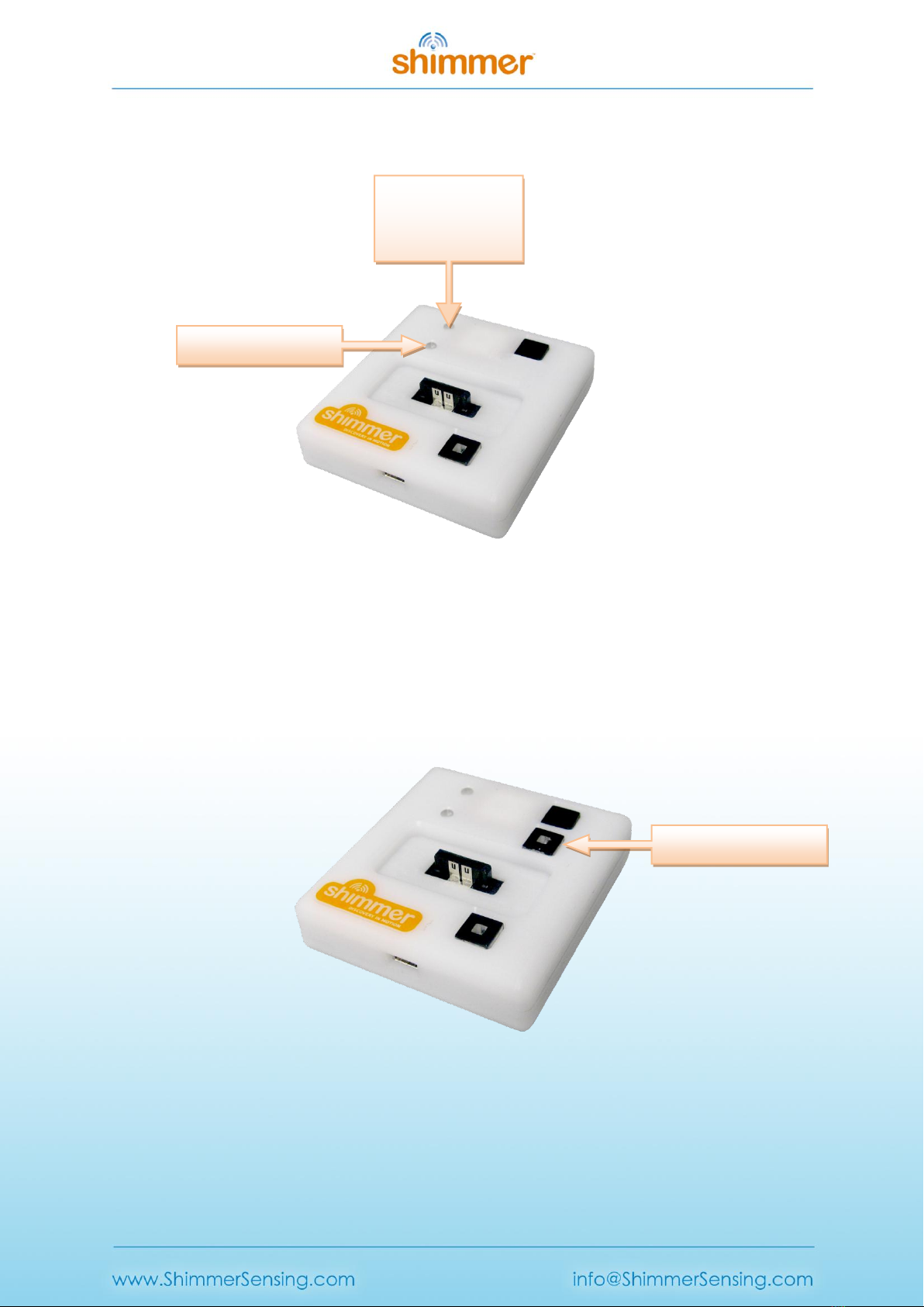
Whilst there have been several Dock design iterations, the current Dock is the Shimmer Dock v3,
which is best identified by a square white enclosure, with a power/reset
1
button containing an LED
for power indication, a black user button and an LED indicator (see Figure 1-1).
Figure 1-1 Shimmer Dock –enclosure view
The different features of the Dock are summarised in Table 1-1.
Item
Shimmer2/2r
Shimmer3
Power/Reset Button1
Power-ON/Reset (quick press)
or Power-OFF (hold for 8s)
Reset (quick press)
Power/Reset Button Indicator
Solid Green when Shimmer is powered on
User Button
Application specific signal to Shimmer
Charge Indicator
Solid Yellow during primary charging state
MicroSD Indicator
Blinks Blue with host PC access to Shimmer microSD
UART Indicator
Blinks Orange during programming (BSL) or UART activity
Table 1-1 Shimmer Dock features
1
The Power on/off function of the Power/Reset Button applies to Shimmer2/2r only. To power on/off a
Shimmer3, the slide switch on the device must be used.
LED Indicator
Power/Reset Button
User Button
Mini USB
Shimmer Connector
Copyright © Shimmer 2016
Realtime Technologies Ltd Shimmer Dock User Guide
All rights reserved Rev 1.8
4
Internally, the Dock also contains a DIP switch, which is used to ensure compatibility with legacy
devices. Your Dock will ship in the appropriate configuration for the version of Shimmer hardware
that you have ordered. However, if you want to change the configuration to use it with a different
hardware version, you may do so by opening the Dock enclosure. This involves removing the black
rubber feet from the underside of the Dock to reveal four screws which should be removed before
opening the plastic.
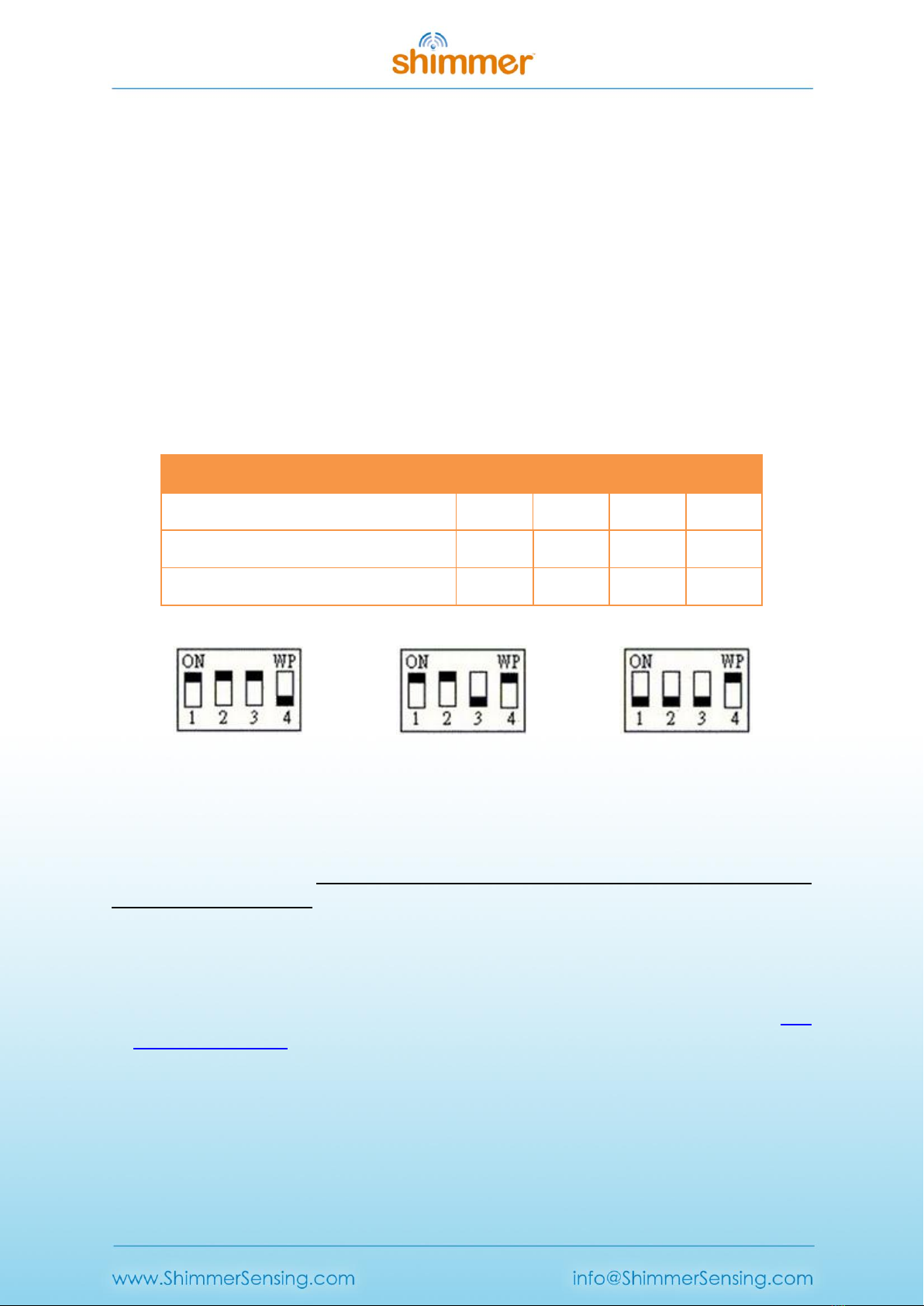
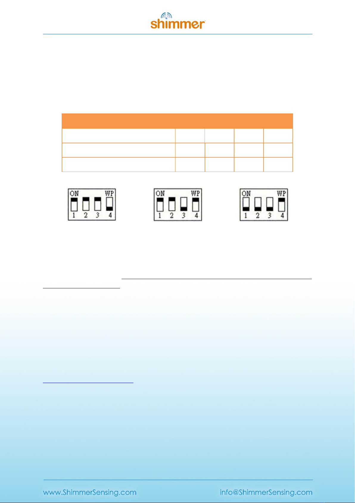
The valid DIP switch configuration options are listed in Table 1-2 and illustrated in Figure 1-2. Users
of Shimmer3 should not change the configuration from that recommended below. Users of
Shimmer2/2r should use the “legacy configuration” for most purposes (e.g. programming firmware
and SD card access). In the event that problems are encountered accessing the SD card for
Shimmer2/2r, which can occasionally occur due to driver incompatibility issues on certain PCs, the
“SD card access only” configuration should be used. Note that in this configuration, programming of
the Shimmer is not possible.
Function
Switch 1
Switch 2
Switch 3
Switch 4
Shimmer3 recommended configuration
1
1
1
0
Shimmer2/2r legacy configuration
1
1
0
1
Shimmer2/2r SD card access only
0
0
0
1
Table 1-2 Shimmer Dock DIP switch configuration options
Figure 1-2 DIP switch configuration: Shimmer3 (left), Shimmer2/2r legacy (centre), Shimmer2/2r SD
card access only (right)
The Dock connects to a PC via a USB cable. Whilst drivers for the microSD Card Access should already
exist on your PC, you will need to manually install USB Serial Converter drivers to use the Dock for
programming the Shimmer. You should perform the installation of these drivers before you first
connect your Dock to the PC.
Warning: If you connect the Dock to a PC do not allow windows to install the driver automatically.
1.1. USB Serial Converter Driver Installation
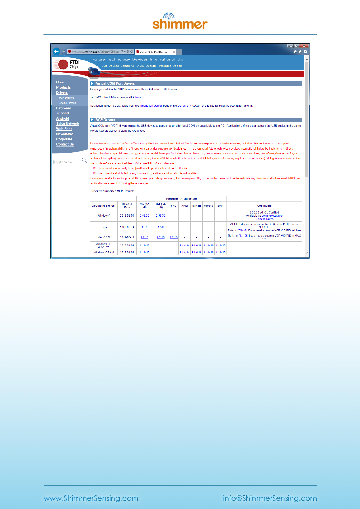
1. The USB Serial Converter drivers for the Programming Dock can be downloaded from the FTDI
Chip Drivers webpage (see Figure 1-3). Download and install the driver to match your operating
system.
Copyright © Shimmer 2016
Realtime Technologies Ltd Shimmer Dock User Guide
All rights reserved Rev 1.8
5
Figure 1-3 USB Serial Converter Driver Download
2. Connect the Dock with a powered USB Port of your PC.
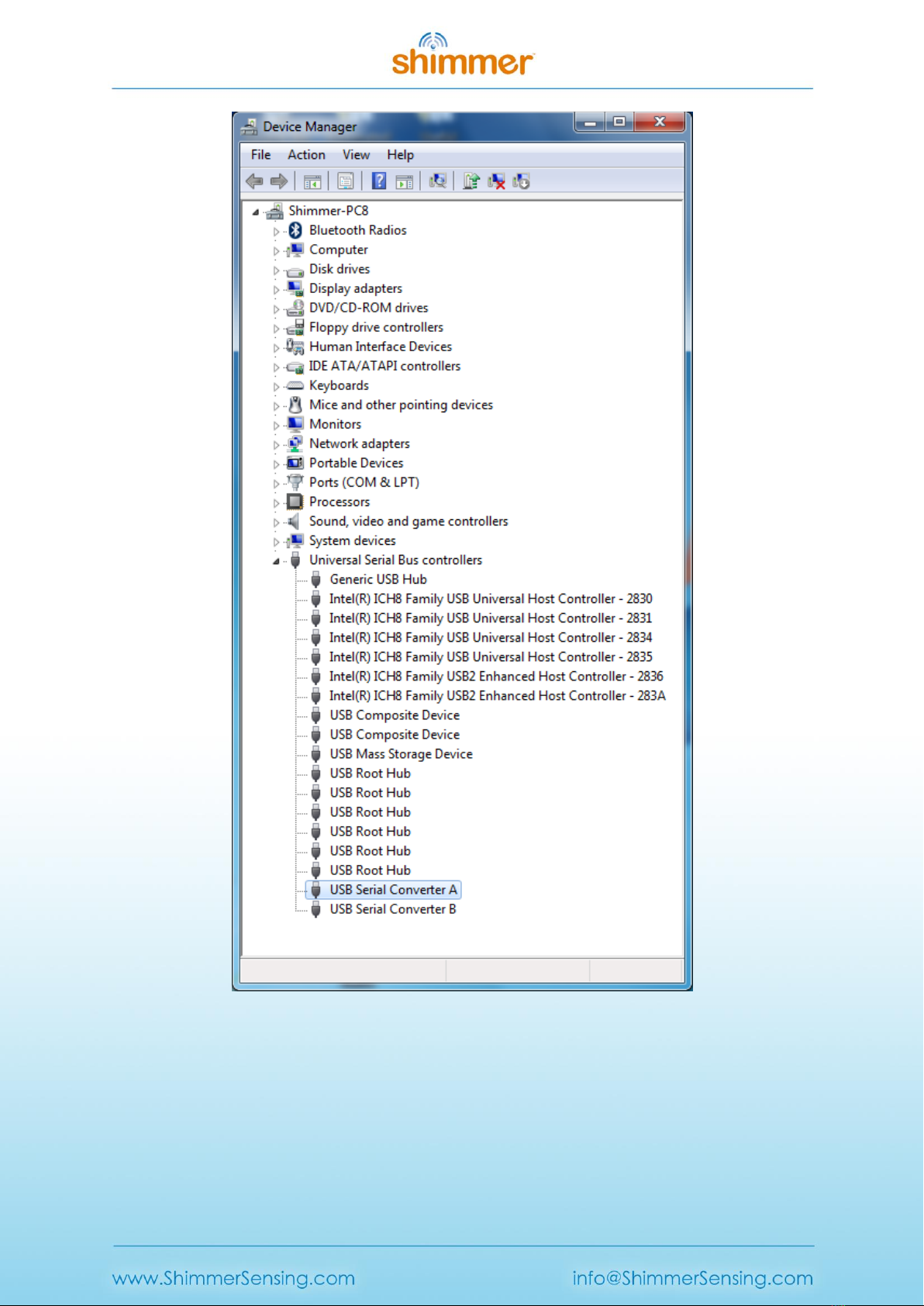
3. Verify your system settings:
I. From the Control Panel, select Device Manager (in Windows this is found from Control Panel
→ System → Hardware → Device Manager or by typing devmgmt.msc in the Start menu) and
expand the Universal Serial Bus controllers entry as shown in Figure 1-4.
II. You should see at least two entries for USB Serial Converter (the other entries will vary with
system configuration and may not match the image above exactly).
Copyright © Shimmer 2016
Realtime Technologies Ltd Shimmer Dock User Guide
All rights reserved Rev 1.8
6
Figure 1-4 Device Manager showing USB Serial Converter A and B
III. Double-click on each USB Serial Converter entry and under the General tab, confirm that the
manufacturer is FTDI. Then, under the Advanced tab, make sure the Load VCP checkbox is
ticked (see Figure 1-5). If the checkbox isn't ticked, you will need to tick for each Serial
converter and then unplug and re-insert the Dock.

Copyright © Shimmer 2016
Realtime Technologies Ltd Shimmer Dock User Guide
All rights reserved Rev 1.8
7
Figure 1-5 USB Serial Converter Properties
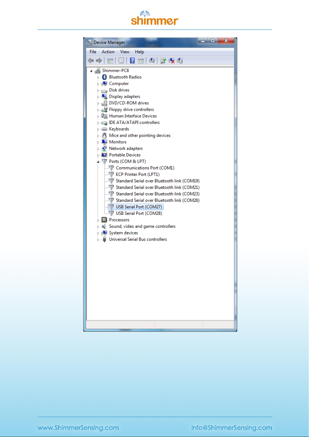
IV. Next, under the Ports (COM & LPT) entry in the Device Manager, you should see two new
USB Serial Port entries, each with an associated COM port number, as shown in Figure 1-6.
Copyright © Shimmer 2016
Realtime Technologies Ltd Shimmer Dock User Guide
All rights reserved Rev 1.8
8
Figure 1-6 Device Manager showing Dock USB Serial Ports
V. Double-click on each of these USB Serial Port entries and, under the Port Settings tab, click
on Advanced...in the Miscellaneous Options at the bottom right-hand side of the window,
ensure that Set RTS On Close is ticked, as shown in Figure 1-7.

Copyright © Shimmer 2016
Realtime Technologies Ltd Shimmer Dock User Guide
All rights reserved Rev 1.8
9
Figure 1-7 Advanced Port Settings: Select Set RTS On Close
1.2. Placing a Shimmer in the Shimmer Dock
The Dock connects to the Shimmer via the External Connector. The External Connector is keyed and
does not require force to insert. Insert the Shimmer with the Bluetooth ID label facing away from the
USB cable.
Warning: Forcing the connector may cause permanent damage to your Shimmer.
When the Shimmer is placed in the Dock, the green LED on the Power/Reset button on the dock will
light up green if the Shimmer is powered on. If it does not light up then one of the following may
have occurred:
Shimmer unit may be powered off.
Shimmer unit may not be inserted properly.
The Dock may not be powered via the USB cable.
Ensure that the Shimmer unit is inserted properly and that the programming dock is powered via the
USB cable. For the Shimmer2/2r, pressing the Power/Reset button on the dock or the reset button
on the Shimmer unit will power on the device. For Shimmer3, use the slide-switch on the side of the
device to ensure that it is powered on.
Copyright © Shimmer 2016
Realtime Technologies Ltd Shimmer Dock User Guide
All rights reserved Rev 1.8
10
1.3. Charging the Shimmer
In order to use the Dock as a charging device, simply connect the USB cable of the Dock to a
powered USB socket and insert the Shimmer unit into the Dock.
Note: You should make sure your Dock is powered when a Shimmer is docked as the Shimmer
battery will discharge if it is left idle in a Dock that is not powered.
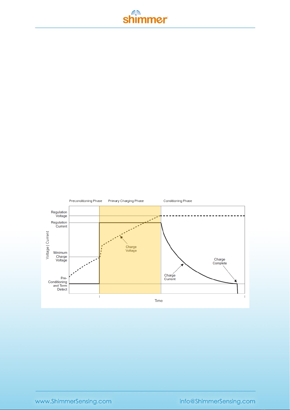
The state of the charge indicator LED is an indication of charge phase for the battery. There are three
phases to Shimmer battery charging, illustrated in Figure 1-8. The background colour on the graph in
Figure 1-8 indicates the colour of the charge indicator LED on the Dock during each phase.
Phase 1 is a Preconditioning Phase and is only required when the battery voltage has dropped below
a minimum threshold. The battery voltage should not drop below this minimum threshold with
normal everyday use however if a Shimmer is left idle for a long period of time the battery may self-
discharge to a voltage below the minimum threshold. During the Preconditioning Phase a low
current (12.5mA) is applied to bring the voltage to the Minimum Charge Voltage. The length of pre-
conditioning will depend on the extent to which battery is discharged. For example a Shimmer that
has been unused for months and was stored discharged may have a lengthy pre-conditioning phase.
For the most efficient recharging after a deep discharge, it is recommended to program the Shimmer
unit with the Sleep firmware image. During the Preconditioning Phase the charge indicator LED on
the Dock will be off.
Figure 1-8 Shimmer Battery Charging Phases. The background colour on the graph indicates the
colour of the charge indicator LED on the Dock during this phase.
Phase 2 is the Primary Charging Phase. This phase is the standard charging phase and involves the
application of a constant current (125mA) to bring the battery voltage to the Regulation Voltage
level. During this phase the charge indicator LED on the Dock will illuminate yellow.

Copyright © Shimmer 2016
Realtime Technologies Ltd Shimmer Dock User Guide
All rights reserved Rev 1.8
11
Phase 3 is the Conditioning Phase. The charger will continue to condition the battery while the
Shimmer remains inserted in the charger. For maximum operating life allow as much conditioning
time as your needs allow. During this Phase the charge indicator LED on the Dock will mostly be off.
Depending on the firmware image that is programmed on the device, the charge indicator LED may
intermittently light up. This is because a heavy load may momentarily bring the battery voltage
below the threshold for the Conditioning Phase, causing the Primary Charging Phase to be re-
entered.
The duration of primary charging for a standard Shimmer battery (3.7V - 450mAh) is typically 4.5
hours. As the Shimmer charges at 125mA/hr and conditions at 12.5mA/hr it is possible to estimate
charge times for larger or smaller batteries. The charger has a 7hr time-out. Users using >800mAh
capacity rechargeable batteries need to increase the charge rate on the Shimmer mainboard to
ensure a full charge, please contact support@shimmersensing.com for further details.
1.4. microSD Card Access
When a Shimmer with microSD card is inserted into a Dock that is connected to a PC, the standard
drivers on the host system should mount the microSD card as though it were a USB flash key.
Depending on the specifics of your system, a few things may happen:
A window may open to display the contents of the Shimmer's flash
A prompt window may pop-up and ask you what you want to do
Nothing may happen, but when you click on the drive letter or volume name associated with
the USB port of the USB Dock, the contents of the Shimmer flash may be browsed.
There are a few requirements for this interaction to work:
1. The Shimmer must be powered.
2. Your SD card must have a compatible format (FAT file system is the only currently supported
method for Shimmer Applications). If this isn't the case, you may be prompted to reformat
the card. Be careful –irreversible data loss will occur! Otherwise a binary/raw disk utility
(such as DD) must be used to copy or access data.
3. Some Shimmer applications may block this ability or limit mounting to specific times during
operation due to legacy compatibility issues, or pending disk operations on Shimmer. This
will result in a blinking blue LED on the Dock followed by a time-out from the HOST, or a blue
LED on the Dock that turns off (media is detected but fails OS poll). You can try to re-insert
the Shimmer, inspect the code, or contact the developer.
1.5. Programming the Shimmer 3
To program a Shimmer, you need a Shimmer Dock or a Consensys Base and must have previously
completed the Internally, the Dock also contains a DIP switch, which is used to ensure compatibility
with legacy devices. Your Dock will ship in the appropriate configuration for the version of Shimmer
hardware that you have ordered. However, if you want to change the configuration to use it with a
different hardware version, you may do so by opening the Dock enclosure. This involves removing
the black rubber feet from the underside of the Dock to reveal four screws which should be removed
before opening the plastic.
Copyright © Shimmer 2016
Realtime Technologies Ltd Shimmer Dock User Guide
All rights reserved Rev 1.8
12
The valid DIP switch configuration options are listed in Table 1-2 and illustrated in Figure 1-2. Users
of Shimmer3 should not change the configuration from that recommended below. Users of
Shimmer2/2r should use the “legacy configuration” for most purposes (e.g. programming firmware
and SD card access). In the event that problems are encountered accessing the SD card for
Shimmer2/2r, which can occasionally occur due to driver incompatibility issues on certain PCs, the
“SD card access only” configuration should be used. Note that in this configuration, programming of
the Shimmer is not possible.
Function
Switch 1
Switch 2
Switch 3
Switch 4
Shimmer3 recommended configuration
1
1
1
0
Shimmer2/2r legacy configuration
1
1
0
1
Shimmer2/2r SD card access only
0
0
0
1
Table 1-2 Shimmer Dock DIP switch configuration options
Figure 1-2 DIP switch configuration: Shimmer3 (left), Shimmer2/2r legacy (centre), Shimmer2/2r SD
card access only (right)
The Dock connects to a PC via a USB cable. Whilst drivers for the microSD Card Access should already
exist on your PC, you will need to manually install USB Serial Converter drivers to use the Dock for
programming the Shimmer. You should perform the installation of these drivers before you first
connect your Dock to the PC.
Warning: If you connect the Dock to a PC do not allow windows to install the driver automatically.
USB Serial Converter Driver Installation procedure outlined earlier in section 0 of this document.
Two methods for programming your device are outlined below; choose the one most suited to your
configuration and preference.
1.5.1. Programming in Windows using Consenys
The Consensys application can be used in Windows to program the Shimmer with pre-compiled
firmware images. The Consensys is available from the Shimmer User Resources or for download from
http://www.shimmersensing.com.

Copyright © Shimmer 2016
Realtime Technologies Ltd Shimmer Dock User Guide
All rights reserved Rev 1.8
13
Programming firmware onto a Shimmer using Consensys is a four step process:
1. Launch Consensys and select the MANAGE DEVICES tab.
2. Insert your Shimmer (ensure it’s powered on) into a Dock or Consensys Base; select the
Shimmer from AVAILABLE SHIMMERS table or from the HARDWARE VISUALISATION graphic and
then press the FIRMWARE button.
3. Select one of Shimmer’s precompiled firmware images provided on the QUICK tab or you
may choose to load a firmware image (a file with a .txt extension) from your PC into
Consensys on the OTHER tab. Press the PROGRAM button to start programming the
Shimmer with the selected firmware.
4. Progress indicators highlight the status of the firmware programming. When programming is
complete, the progress bar will be filled to 100% and the DONE button will be enabled. See
expected Shimmer LED behaviour for provided firmware images In section Error! Reference
source not found..
2. Legacy
2.1. Compatibility
The previous version of the Shimmer Dock (v2.1) can be identified by the two LED indicators –one
for MicroSD/UART activity and the other for charge indication, as shown in Figure 2-1. It should be
noted that this version of the Dock is not fully compatible with Shimmer3. The charge indicator will
not light for Shimmer3 and SD card access through the dock will not work on some PCs.
3
4
2
1
Figure 1-9 Shimmer3 firmware programming using Consensys
Copyright © Shimmer 2016
Realtime Technologies Ltd Shimmer Dock User Guide
All rights reserved Rev 1.8
14
It should also be noted that the Shimmer Dock (v2.1) (and previous versions) do not contain the DIP
switches that are present on Shimmer Dock v3 to change the configuration of the Dock.
Figure 2-1 Shimmer Programming Dock v2.1
2.2. GPS
A previous version of the Shimmer Dock (v2.0) included GPS capability. This section only applies to
versions of the Dock with GPS capability (evident from the presence of a GPS button as in Figure
2-2).
Figure 2-2 Shimmer Programming Dock v2.0
The GPS Enable button is used to switch between GPS and host computer UART functionality. In GPS
mode, the indicator on the button will blink green while GPS location is being acquired. The indicator
GPS Button
MicroSD Indicator/
UART Indicator
Charge Indicator

Copyright © Shimmer 2016
Realtime Technologies Ltd Shimmer Dock User Guide
All rights reserved Rev 1.8
15
will turn solid after a lock is reached. This requires a clear view of the sky or placement on a
windowsill or ledge.
The GPS module will transmit serial GPS NMEA sentences to the docked Shimmer's external
connector UART lines. This data can be used for application synchronization or localization.
Configuration commands use the MTK NMEA format. For more information on the commands, data
format and operational parameters of the GPS module see the Shimmer GPS/PRES User Guide
available at www.shimmersensing.com in downloads.
Toggling GPS Enable so that the indicator is off will select UART functionality. The UART lines will
now pass through to the USB UART on the host computer. In this mode, operation matches the
previous Shimmer Dock accessories. A common UART indicator is used for both the host UART, and
the BSL programming interface UART. Beyond the indicator difference, the UART mode behaves like
legacy USBREADER or USB Dual UART docks.
While the Dock has a memory retention feature for GPS almanac data, after a period of inactivity, or
geographic movement, initialization of GPS almanac data may take up to an hour. Without a clear
sky-view, data output from the GPS module will be incomplete. This condition is indicated by a
persistent blinking GPS indicator or blank fields in output data. When confronted with scenario try a
different location. In some indoor cases, insufficient sky-view, RF blocking building materials, or
shadows from adjacent structures will limit GPS functionality.
Note: Some example Shimmer applications may operate differently or unpredictably when the GPS
mode is selected.
2.3. Programming the Shimmer 2r
This section deals with programming the Shimmer with pre-compiled Firmware images. For details
on modifying Firmware please refer to the Firmware section of the Shimmer User Manual.
A Bootstrap Loader application is used in Windows to program the Shimmer 2/2r with pre-compiled
firmware images. Bootstrap Loader applications are available from the Shimmer 2r User Resources.
You should copy the application folder to a suitable location on your PC. The application does not
require installation.
For the application to function correctly you must have previously completed the USB Serial
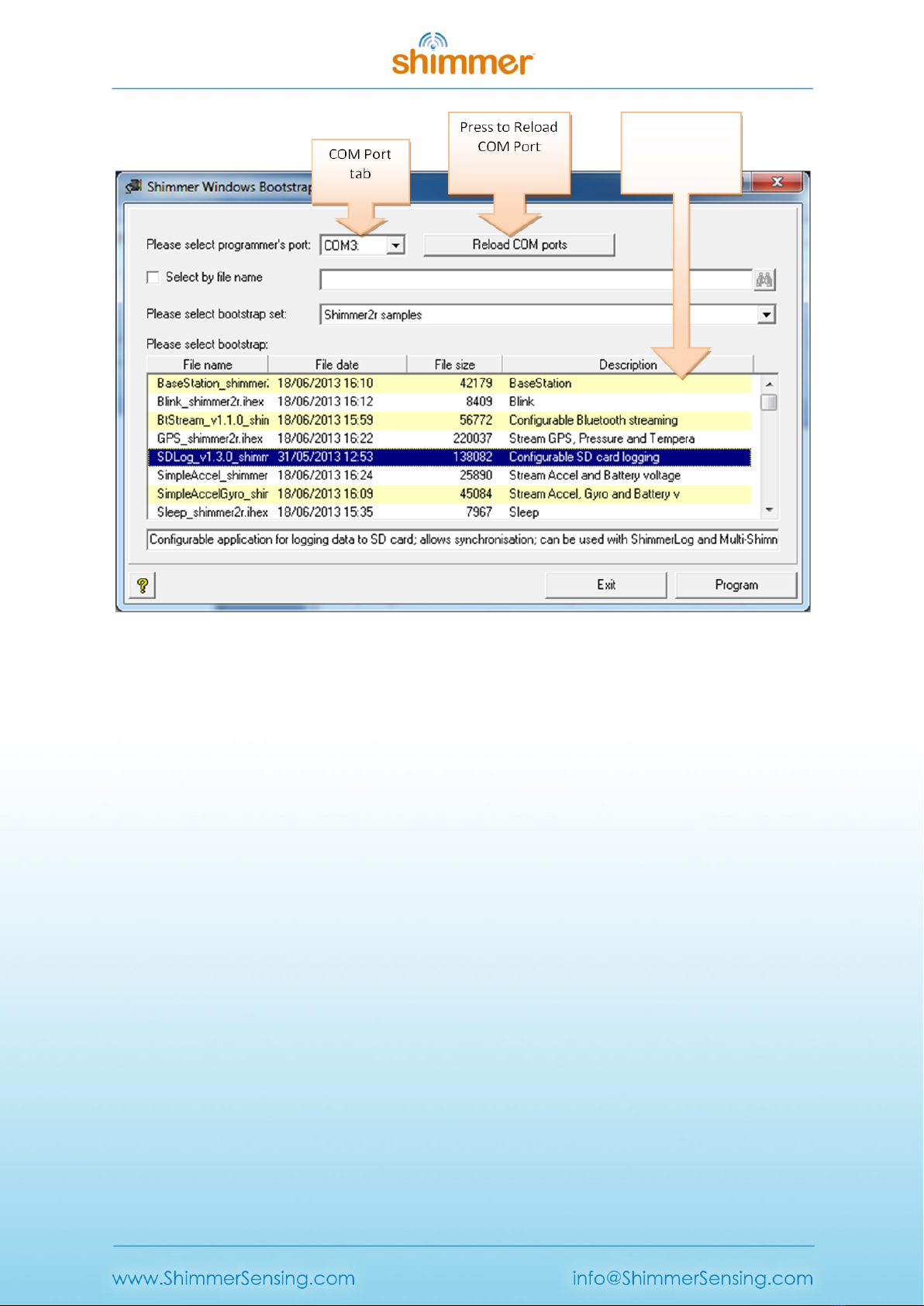
Converter Driver Installation procedure outlined earlier in this document. For Shimmer2/2r: When
you run BSL430, the application will automatically attempt to detect the serial port associated with
the Dock, this will be indicated by the COMxx entry in the port tab (illustrated in Error! Reference
source not found.) where xx is the serial port number. If no port is displayed, try pressing the
Reload COM ports button. If that fails, first check the cable, then revisit the USB Serial Converter
Driver Installation procedure outlined earlier in this document.
Copyright © Shimmer 2016
Realtime Technologies Ltd Shimmer Dock User Guide
All rights reserved Rev 1.8
16
Figure 2-3 BSL430 Programming application
When you run BSL430, the application will automatically attempt to detect the serial port associated
with the Dock, this will be indicated by the COMxx entry in the port tab (illustrated in Error!
Reference source not found.) where xx is the serial port number. If no port is displayed, try pressing
the Reload COM ports button. If that fails, first check the cable, then revisit the USB Serial Converter
Driver Installation procedure outlined earlier in this document.
The BSL430 application includes a number of precompiled Firmware images - usually a file with an
.ihex extension. You may choose to load one of the provided images or, alternatively, tick the "Select
by file name" checkbox and browse to the location of the image on your PC.
If you choose one of the provided images (by leaving the "Select by file name" checkbox unchecked),
it is very important that the chosen image matches the target platform (Shimmer1, Shimmer2,
Shimmer2r or Span) or unpredictable behaviour may occur; the "Please select bootstrap set:" drop-
down menu can be used to select the correct set of images. Next, use the scroll bar and selection
tabs to browse and select a firmware image from among the available options. If you do not see a
list of firmware images please consult the Firmware Images not listed section.
As a test case we will program the Shimmer with the Blink firmware:
1. Select either the Blink_shimmer2r.ihex or Blink_shimmer2.ihex file (depending on your
Shimmer version) and press the Program Button.
Firmware
Images Panel

Copyright © Shimmer 2016
Realtime Technologies Ltd Shimmer Dock User Guide
All rights reserved Rev 1.8
17
2. A Windows such as that illustrated in Error! Reference source not found. should pop up. In
addition, the UART Indicator light on the Dock will flash. Depending on the program size, it
may take up to five minutes to program a Shimmer, but blink is quite small and the firmware
update should complete quickly.
Figure 2-4 BSL430 Programming
3. The LEDs on your Shimmer should be blinking- congratulations you have programmed your
Shimmer! If you experience difficulty, verify that your Shimmer is powered on and the
correct programming port COM port is selected then try again.
3. Troubleshooting
USB UART drives fail to load
There is no COM Port listed in the COM Port tab in the BSL430 application
Occasionally the USB UART drivers will fail to load. This condition typically happens when the Dock
has been unplugged and is often indicated by a solid UART activity LED. The simple fix is to unplug
the USB cable and retry. If this process fails to remedy the situation, please contact Shimmer
Research support for assistance.
Firmware Images not listed
There are no firmware images listed in Firmware Images Panel in the BSL430 application.
Firstly make sure that the Select by file name option is NOT ticked. Also make sure that you have
selected the correct bootstrap set for your platform using the Please select bootstrap set option (e.g.
Shimmer2r samples). If that fails to rectify the problem be aware that the folder structure for the
BSL430 application has to be maintained. You may have changed the structure by moving the
Copyright © Shimmer 2016
Realtime Technologies Ltd Shimmer Dock User Guide
All rights reserved Rev 1.8
18
location of bsl430.exe with respect to the bootstraps folder or vice versa. Ensure that the folder
structure is in its original format as in Figure 3-1
Figure 3-1 BSL430 folder structure
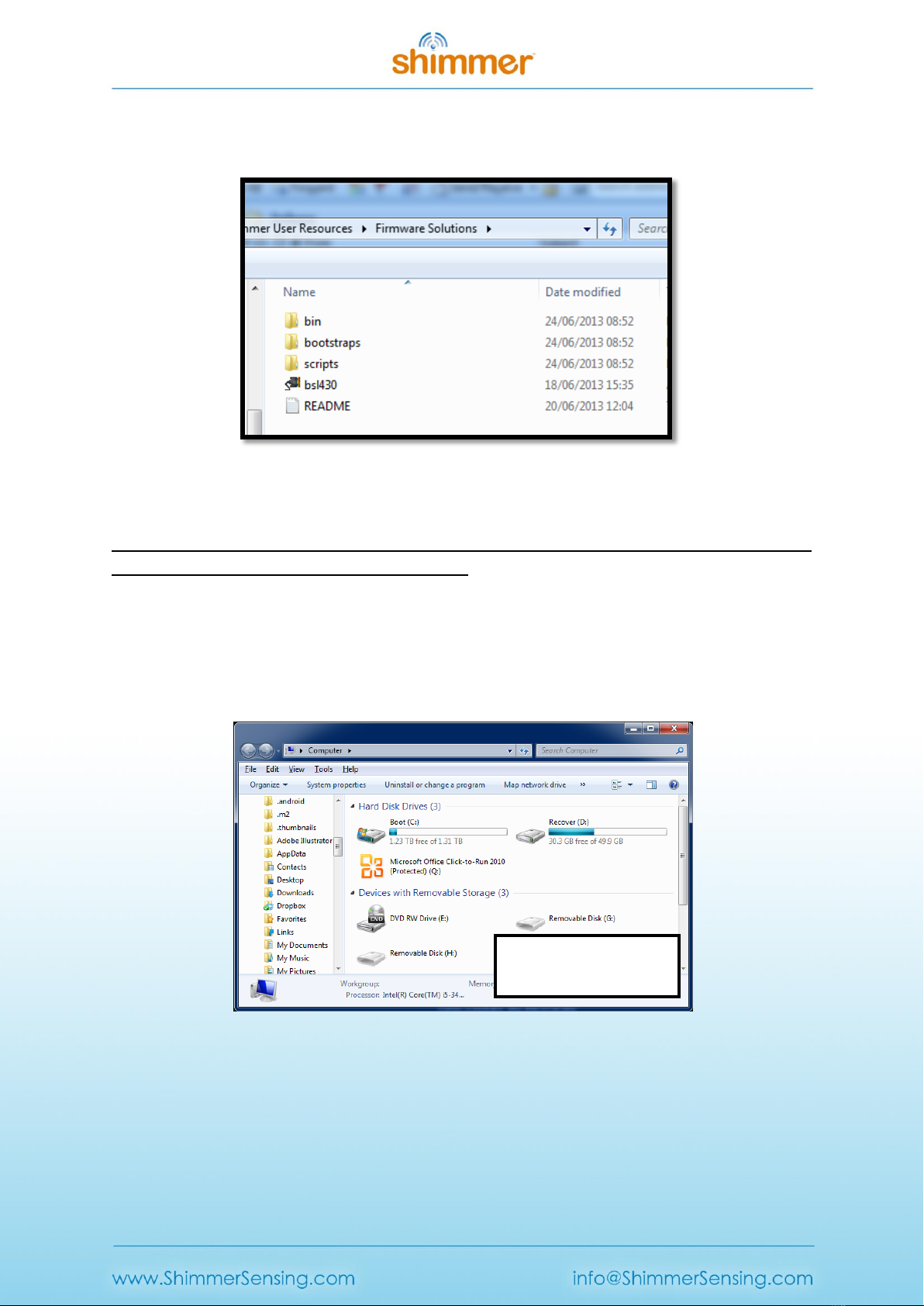
PC fails to recognise the SD card
I have inserted an SD card into my Shimmer unit but the PC fails to recognise it when I view the list
of Devices with Removable Storage as in Figure 3-2.
Try one or more of the suggested options below to attempt to resolve the problem.
1. Make sure that the Shimmer Dock drivers installed correctly.
2. Power off and power on your Shimmer unit.
3. Unplug and re-plug the Shimmer Dock.
Figure 3-2 Shimmer SD Card NOT detected by PC
Shimmer SD card NOT
detected by PC

Copyright © Shimmer 2016
Realtime Technologies Ltd Shimmer Dock User Guide
All rights reserved Rev 1.8
19
Figure 3-3 Shimmer SD Card detected by PC
On certain PCs, users of the Shimmer2/2r and the Shimmer Dock v2.1 (and earlier) may experience
SD card access problems, due to Windows drivers causing a race condition, which means that the SD
card control is not correctly handed over from the Shimmer to the PC. This problem has been
rectified in Shimmer Dock v3. The problem can be characterised by the symptoms described above
(Shimmer SD card not detected by PC) or by one of the following:
1. SD card needs to be formatted:
oThe PC pops up a warning message telling the user that the SD card needs to be
formatted.
oWhen the user says “Yes” to formatting the SD card, the format operation fails.
2. SD card detected but files not accessible:
oThe SD card appears to be detected and shows up as a Removable Disk in My
Computer.
oWhen the user attempts to open directories or files, an error occurs and the SD card
subsequently appears not to be detected by the PC.
If this occurs, you should attempt the following steps:
Powercycle the Shimmer on the Dock (long press of dock reset button, followed by short
press of the Reset button on the Dock).
Remove the Shimmer from the Dock.
Unplug the USB connection between the PC and the Dock.
Reconnect the USB connection between the PC and the Dock.
Check that the Dock driver settings are correct, according to Section 1.1 of this User Guide.
Replace the Shimmer on the Dock and ensure that it is powered on.
If these troubleshooting steps fail to resolve the problem with Shimmer2/2r and Shimmer Dock, you
should consider purchasing the latest release of the Shimmer Dock. This Dock should be configured
for Shimmer2/2r SD card access only (see Section 1 of this document for details).
Shimmer SD card
detected by PC
Table of contents


