Shindaiwa 78701 Owner's manual

SHINDAIWA OWNER’S/OPERATOR’S MANUAL
Minimize the risk of injury to yourself and others!
Read this manual and familiarize yourself with the
contents. Always wear eye and hearing protection
when operating this unit.
WARNING!
MULTIPURPOSE POLE
PRUNER ATTACHMENT 78701
For Models AH230, AH231, AH242,
AHS231, AHS242, P230, P231, PB230,
T230, T231, T242, T2510
X7502890802
01/11

2
Throughout this manual are special at-
tention statements.
DANGER!
A statement preceded by the trian-
gular attention symbol and the word
“DANGER” indicates an imminently
hazardous situation which, if not
avoided, WILL result in death or seri-
ous injury!
WARNING!
A statement preceded by the trian-
gular attention symbol and the word
“WARNING” indicates a potentially
hazardous situation which, if not
avoided, COULD result in death or
serious injury.
CAUTION!
A statement preceded by the word
“CAUTION” contains information that
should be acted upon to avoid dam-
age to the machine.
IMPORTANT!
A statement preceded by the word
“IMPORTANT” is one that possesses
special signicance.
NOTE:
A statement preceded by the word
“NOTE” contains information that is handy
to know and may make your job easier.
Attention Statements
Introduction Safety Precautions
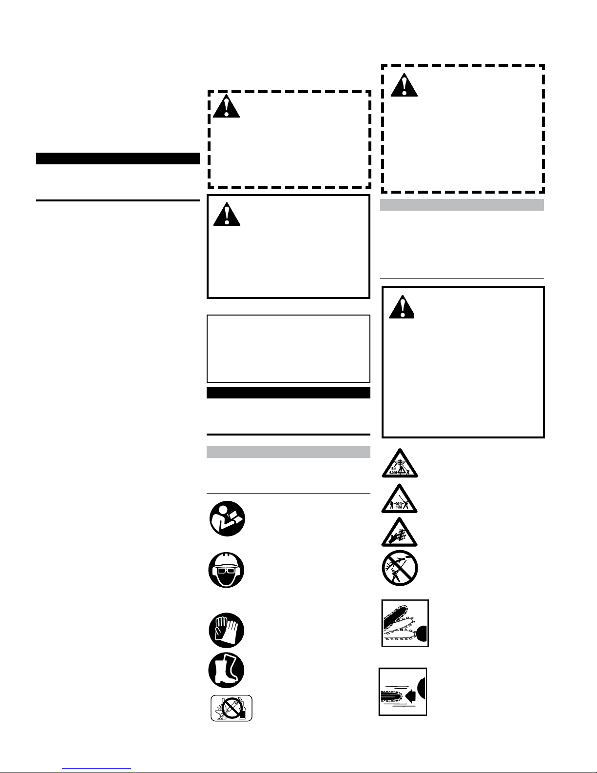
Read and follow this manual, make sure
anyone using the trimmer does likewise.
Failure to do so could result in serious
personal injury or machine failure. Keep
this manual for future reference.
Always wear a hard hat to reduce the risk
of head injuries during operation of this
machine.
In addition, always wear eye and hearing
protection. Shindaiwa recommends wearing
a face shield as additional face and eye
protection.
Wear heavy duty, non-slip gloves.
Safety tip shoes or boots with non-slip
sole should be worn.
The Shindaiwa Pole Pruner Attachment
is designed and built to deliver superior
performance and reliability without
compromise to quality, comfort, safety or
durability.
As an owner/operator, you'll soon
discover for yourself why Shindaiwa is
simply in a class by itself!
While every attempt has been made to
provide the latest information about your
Shindaiwa product, there may be some
differences between your attach- ment
and what is described here. Echo, Inc.
reserves the right to make changes
to products without prior notice and
without obligation to make alterations to
components previously manufactured.
The procedures described in this manual
are intended to help you get the most
from your machine as well as to protect
you and others from harm. These pro-
cedures are guidelines for safe opera-
tion under most conditions, and are not
intended to replace any safety rules and/
or laws that may be in force in your area.
If you have questions regarding your
power tool, or if you do not under-
stand something in this manual, your
Shindaiwa dealer will be glad to assist
you.
You may also contact Shindaiwa at the
address printed on the back of this
manual.
NOTE:
For specic maintenance and safety infor-
mation about your T230/231, AH230/231,
or PB230, consult the owner's manual
provided with it. If it has been lost or
misplaced, contact a Shindaiwa dealer for
a replacement.
WARNING!
THE PRUNER IS NOT INSULATED
AGAINST ELECTRICAL SHOCK!
Approaching or contacting electrical
line with the pruner could cause
death or serious injury. Keep the
pruner at least 33 feet (10 meters)
away from electrical lines or branch-
es that contact electrical lines.
IMPORTANT!
The information contained in these
instructions describes components
available at the time of publication.
PAGE
Contents
WARNING!
A pole pruner runs at very high
speeds and has the potential to do
serious damage if misused, abused
or mishandled. To reduce the risk
of injury, you must maintain control
at all times, and observe all safety
precautions during operation. Never
permit a person without train-
ing or instruction to operate this
pruner!
Introduction ............................................ 2
Attention Statements ............................. 2
Safety Precautions.................................. 2
Operating Precautions .......................... 3
Safety Labels........................................... 4
Operating the Pruner ............................ 4
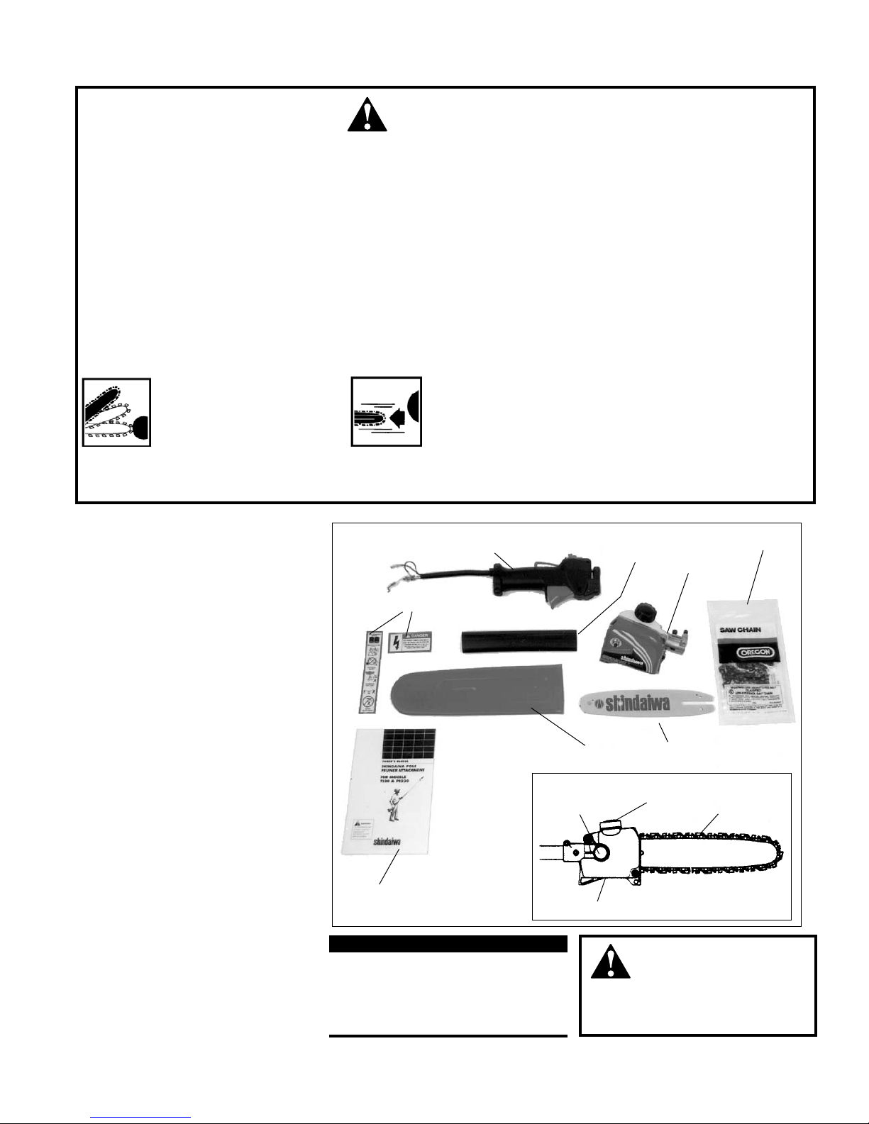
Product Description............................... 5
Specifications.......................................... 6
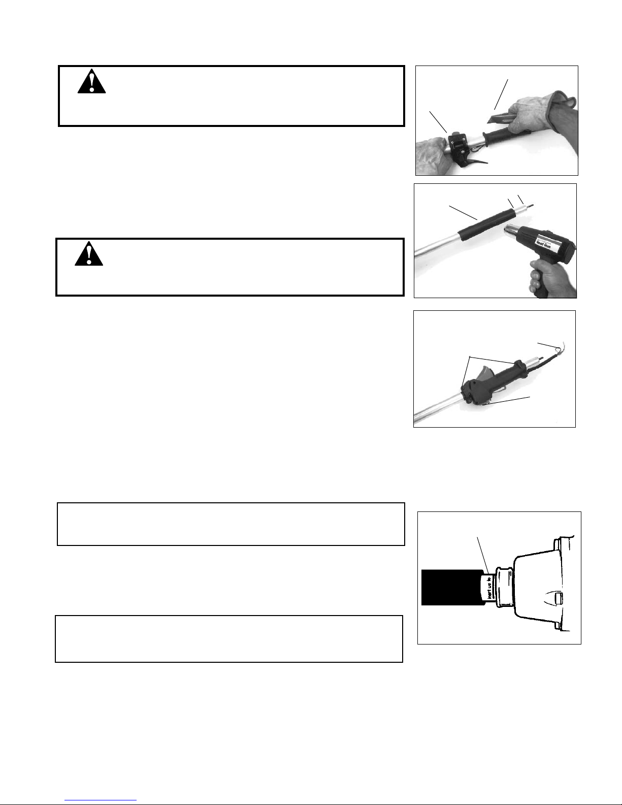
Assembly............................................... ..6
Filling the Chain Oiler Reservoir ......... 8
Maintenance ........................................... 9
Sharpening the Chain ......................... 10
Troubleshooting Guide ....................... 12
This product conducts electricity. Keep
the product and/or operator a minimum
distance of 15 feet (4.5 meters) away
from electrical sources and power lines.
Keep bystanders at least 50 feet (15 me-
ters) away from the operating trimmer
to reduce the risk of being struck by
falling objects or thrown debris.
The blades / cutting attachments are
SHARP! Handle with care.
Be aware of the danger of falling debris.
Beware of pinching.
Pinching the saw along the tip of the
guide bar may force the bar back
rapidly toward the operator. Pinching
can occur whenever wood closes in
around the moving chain.
Beware of Kickback!
Kickback can occur whenever the
tip of the guide bar touches an object
while the saw is operating. Kickback
may force the bar up and back
toward the operator with lightning-
like speed!
Never operate power equipment of any
kind if you are tired or if you are under
the inuence of alcohol, drugs, medica-
tion or any other substance that could
affect your ability or judgement.

3
CAUTION!
Always maintain the Pole Pruner Tool according to this owner’s manual and follow the recommended scheduled
maintenance.
Never modify or disable any of the pruner’s safety devices.
Always use genuine Shindaiwa parts and accessories when repairing or maintaining this machine.
Do not make unauthorized modications to the pole pruner.
When transporting the pole pruner in a vehicle, tie it down securely to prevent fuel spillage or damage to the machine.
Always clear your work area of trash or hidden debris to help ensure good footing.
Keep the chain sharp and properly adjusted.
Keep the pole pruner as clean as possible. Keep it free of loose vegetation, mud, debris, etc.
Operating Precautions
This Shindaiwa pole pruner
attachment is specically de-
signed for use on the Shindaiwa
T230/231 grass trimmers,
AH230/231 articulating hedge
trimmers, or PB230 power broom.
Installation and/or use on any
other model, brand or type of
power tool is not approved by
Shindaiwa. Attempts to use on
non-approved models can dam-
age the equipment and cause
accidents, serious injury or death.
Make sure the chain and sprocket
are correctly adjusted before
operating the pruner (see assem-
bly for adjustment procedures).
Never attempt chain adjustment
with the engine running!
Always make sure the cutting at-
tachment is properly installed and
rmly tightened before operation.
WARNING!
Never use a cracked or warped
guide bar: replace it with a service-
able one and make sure it ts
properly.
If a saw blade should bind fast in
a cut, shut off the engine immedi-
ately. Push the branch or tree to
ease the bind and free the blade.
Before starting the engine, make
sure the saw chain is not contact-
ing anything.
When cutting a limb that is under
tension, be alert for springback so
that you will not be struck by the
moving limb.
Always run at wide open throttle
(WOT) before contacting material
to be cut.
Always stop the engine imme-
diately and check for damage if
you strike a foreign object or if the
machine becomes tangled. Do not
operate with broken or damaged
equipment.
Stop the machine immediately if
it suddenly begins to vibrate or
shake. Inspect for broken, miss-
ing or improperly installed parts or
attachments.
Never transport the pruner or set
it down with the engine running.
An engine that’s running could be
accidently accelerated causing
the chain to rotate.
Make sure the scabbard is in
place when transporting the
pruner.
When carrying by hand, the chain
should be pointing backward.

4
Safety Labels
IMPORTANT!
Safety and Information Labels: Make
sure all safety and information labels
are
undamaged, readable and up to date. Immediately replace damaged or
missing labels.
This Attachment comes with safety labels shipped loose in the box. Attach
these safety labels.
New labels are available through your local authorized Shindaiwa dealer.
Always operate with both
hands firmly gripping the
machine.
Wear nonslip heavy-duty
work gloves to improve
your grip on the pole
pruner handle. Wear
snug-fitting clothes that
also permit freedom
of movement. NEVER
wear shorts!
Always wear a hard hat
to reduce the risk of head
injuries during operation of
this machine.
Always wear eye and hearing protection.
Shindaiwa recommends wearing a face shield as
additional face and eye protection.
Wear sturdy footwear
with nonslip soles to provide
good footing. Steel-toed safety
boots are recommended. Never
operate this product barefoot.
Keep a proper footing and
do not overreach—main-
tain your balance at all
times during operation.
Operating the Pruner
Never operate the pruner at
an angle greater than 60°
in order to reduce the risk of
being struck by falling objects
during operation.
Keep bystanders at least 50 feet (15 meters) away
from the operating pruner to reduce the risk of
being cut by moving saw chain or struck by falling
objects or thrown debris.
WARNING!
To avoid the chance of serious injury or
death, follow these safety precautions
during operation:
IMPORTANT!

5
Product Description
IMPORTANT!
The terms “left”, “left-hand”, and “LH”;
“right”, “right-hand”, and “RH”; “front”
and “rear” refer to directions as viewed
by the operator during normal opera-
tion.
Prior To Assembly
Familiarize yourself with the Shindaiwa
pole pruner tool and its various compo-
nents. Understanding your machine helps
ensure top performance, longer service
life, and safer operation.
Before assembling, make sure you have all
the components required for a complete
unit:
Gearcase assembly
Guide Bar
Saw Chain
Heat-shrink Collar
Throttle Grip w/interlock
Scabbard
Owner's/Operator's manual
Assembly Tool (s)
Safety Labels
Carefully inspect all components making
sure they are not damaged.
WARNING!
Do not make unauthorized modi-
cations or alterations to your pole
pruner or its components.
WARNING!
Both kickback and pinching may
cause you to lose control of the pole
pruner tool which could result in
serious personal injury. Do not rely
exclusively on the safety device
built into the pruner! You must take
several steps to keep your jobs free
from accident or injury:
1. Understand kickback and pinch-
ing! You can reduce or eliminate
the element of surprise. Sudden
surprises contributes to accidents.
Kickback and Pinching Safety Precautions
2. Keep a rm grip on the pole pruner
with both hands whenever the en-
gine is running. A rm grip will help
you reduce the affects of kickback
and pinching as well as maintain
control
of the machine.
3. Make sure the area in which you
are cutting is free from obstruc-
tions. Do not let the nose of the
guide bar contact a log, branch, or
any other obstructions which could
be hit while you operate the pole
pruner tool.
4. Cut at high engine speeds.
5. Follow the manufacturer’s instruc-
tions for sharpening and maintain-
ing the chain.
6. Use only the replacement bar and
chain or equivalent as specied by
the manufacturer.
Beware of pinching.
Pinching the saw along the
tip of the guide bar may force
the bar back rapidly toward
the operator. Pinching can
occur whenever wood closes in around the
moving chain.
Beware of Kickback!
Kickback can occur when-
ever the tip of the guide bar
touches an object while the
saw is operating. Kickback may force the
bar up and back toward the operator with
lightning-like speed!
Gearcase
Bar Oil Reservoir
Figure 3
Cutting Head
Assembly
Guide Bar and
Chain
Oil Filler Cap
Caution Labels
Throttle Lever Assy. Collar Gearcase
Saw Chain
Guide Bar
Scabbard
Owner's Manual

6
Specications
Length mounted on T230 w/10 inch bar......... 1991 mm (78.4 in)
Dry Weight (Tool only)with bar and chain.........0.91 kg (2.0 lbs)
Guide Bar........3/8" pitch, .043" gauge, 10-inch Micro Lite™
Chain Type................................3/8" pitch Micro Lite™,.043" gauge
Sprockets..............................................................3/8-inch, fixed spur
Gearcase Ratio...........................................................................1.06 : 1
Chain Lubrication....................................Automatic adjustable oiler
Oil Tank Capacity........................................................100 ml./3.9 oz.
Specifications are subject to change without notice.
1. Place the T230 or PB230 on a clean flat
surface, in an upright position.
2. Remove the cylinder cover as instructed
in your unit owner's manual.
3. Loosen the inner throttle cable adjusting
nut with a 10 mm wrench.
4. Lift the throttle cable housing out of the
notch on the powerhead.
5. Remove the throttle cable from the car-
buretor by lifting the Z-shaped cable end
out of the hole. See Figure 5.
Installing The Attachment:
Remove Outer Tube From Powerhead
Hex wrench Shim washer
Tube clamp
Figure 7
Figure 6
Cable
adjusting
nuts
Red
switch
wire
Black
ignition
ground
lead
Figure 5
Pull Z-shaped cable end out of hole
on throttle arm
Figure 4
Lift the corner of the cover
Loosen knob
and disconnect
spark plug
cap
NOTE:
The steps on page 11 through 15 are not necessary for models AH230 and AH231 because they come equipped with an interlock-
ing throttle grip assembly as standard equipment.
6. Disconnect the red stop switch wire by
unplugging the bullet connector.
7. Use the 4 mm hex (Allen) wrench to
loosen the tube clamp screw. See Figure
7. Loosen, but don't remove the screw,
or the D-shaped shim washer will fall
out.
8. Pull the tube assembly out of the clamp.
Set the powerhead aside.

7
Figure 8
Loosen the three
throttle lever clamp
screws
Slice the grip to remove
Installing The Interlock Throttle Grip
■ To avoid serious injury, grip the outer tube securely with one hand and cut
away from that hand when slitting the rubber throttle grip.
WARNING!
1. Place the T230 or PB230 outer tube assembly on a clean, flat surface.
2. Loosen the three screws that hold the throttle trigger assembly to the outer
tube.
3. Slide the trigger assembly down the tube, several inches away from the rubber
grip. Rotate the trigger assembly so it is flat against the work surface.
4. With a utility knife or similar tool, slit the rubber grip lengthwise to release it
from the tube. Use gentle pressure to avoid scarring the outer tube. See Figure
8.
5. Remove the grip and slide the throttle lever from the tube. Discard these parts.
6. Clean surface of tube in grip area.
7. Make a mark on the tube, 2 inches from the upper end. Slide the heat shrink col-
lar onto tube and align its upper end with the mark on the tube. See Figure 9.
8. Using a heat gun or hair dryer, apply heat to the collar until it shrinks and forms
a snug fit around the tube.
9. Slide the new interlock throttle grip assembly onto the tube, and position it over
the collar. Make sure the switch is facing up, and that the throttle cable and
switch wires are positioned toward the powerhead. Using a Phillips screwdriver,
tighten the grip's four clamp screws.
■ Failure to replace the standard throttle grip with the provided interlock throttle grip could
permit unintentional acceleration, which could cause serious injuries or death.
WARNING!
Figure 9
Shrink-fit collar
Apply heat to
the shrink collar
around tube
2-in.
Place the throttle grip
assembly over the
collar and tighten the
four clamp screws
Switch on
"up" side of
tube
Figure 10
Throttle cable and
stop switch wires
towards powerhead
Powerhead Reinstallation
1. Place the powerhead on a clean, flat surface in an upright position.
2. Slide the outer tube into the tube clamp until the outer tube bottoms. It should
go in about 1-1/2 in. (38 mm). If the outer tube stops before bottoming, rotate
it until you feel the inner mainshaft (driveshaft) splines engage the powerhead.
Then push the outer tube all the way in. See Figure 11
Push the outer tube until it bottoms in the
clamp, rotating if necessary.
CAUTION!
Do not remove the D-shaped shim washer! The shim washer prevents damage
from overtightening the tube clamp screw.
CAUTION!
Do not force the lower tube into the powerhead! Excessive force can damage
the components.
Figure 11

8
Lower Tube
Tube Clamp
Clamp
Screw
Handle Grip
Throttle Cable
Assembly
Main
Shaft
3. Position the outer tube so the stop
switch is facing up and the throttle
cable/wire assembly is on top. See
Figure 12.
4. Use the Allen wrench to tighten the
clamp screw firmly. Make sure the
D-shaped shim washer is in place.
(Review Figure 7, pg. 11.)
Figure 12
Reconnecting the Throttle Cable, Switch Wires
Connect The Throttle Cable.
1. Loop the ribbed cable assembly to the top left side of the engine. Confirm that the
black ground wire (with an eyelet on the end) is located between the two cable
adjuster nuts as shown in Figure 13.
2. Connect the Z-shaped end of the throttle cable to the throttle lever on top of the
carburetor as shown in Figure 14.
3. Turn the cable adjuster nuts sufficiently for the throttle cable to fit in the notch
on the fan cover. Make sure the ignition ground lead is located on the rearward
side of the notch. Then, connect the male fitting of the red ignition wire into the
female fitting of the red wire attached to the engine. See Figure 15.
Cable Adjuster Nuts
Ignition Ground
Lead (black)
Throttle
Cable End
Throttle
Cable
End
Ignition
Ground
Lead (black)
Notch
Female Ignition
Wire Fitting
Figure 14
Figure 13
Figure 15

9
Adjusting the Throttle Cable
1. Loosen the two 10mm throttle cable nuts at the fan cover as shown in Figure 16.
Idle Throttle
Position
1/4-inch Throttle
Freeplay
Full
Throttle
Position
Stop on
throttle
body
3. When 1/4-inch of free play is achieved, securely tighten the two 10mm throttle
cable nuts. When the throttle cable is correctly adjusted, and the throttle trigger
is fully depressed (full throttle), the throttle will contact the stop on the throttle
body. See Figure 18.
NOTE:
Apply Never-Seez™ or equivalent on the cylinder cover knob threads for easier
removal.
4. Replace the cylinder cover.
5. Replace the spark plug boot.
Cable Adjuster Nuts
Figure 16
Figure 17
Figure 18
IMPORTANT!
Make sure the stop switch wires do not interfere with throttle functions.
Reposition wires if necessary.
2. Adjust the throttle cable adjuster nuts until you achieve a free play on the throttle
trigger of about 1/4 inch. See Figure 17.

10
1. Place the re-gripped T230, PB230, or AH230 on a clean, flat surface in an upright
position.
For the T230/T231 Trimmers:
2. Loosen, but don't remove the gearcase clamp screw and nut using a 4 mm hex
wrench and an 8 mm open end wrench.
3. Use the 4 mm hex wrench to loosen the gearcase index screw until it is almost
free.
4. Use the 4 mm hex wrench to loosen the four debris shield attachment screws. Loosen
them only enough to free the debris shield assembly from the outer tube. This will make it
easier to reattach the debris shield when converting back to a trimmer.
5. Pull and rotate the debris shield, gearcase, and trimmer head assembly until it slides
off the outer tube. Note: the gearcase and debris shield are connected by the clamp
screw.
NOTE:
The gearcase and debris shield are connected by the clamp screw.
6. The debris shield has two spacers located on either side of the outer tube and
the debris shield bracket. Put the shims and the debris shield/gearcase assem-
bly in a safe place, so that they can be reinstalled later if desired.
Removing the Trimmer/PowerBroom Attachment
Loosen debris
shield screws
Figure 19
Loosen
index
screw
Loosen clamp
screw
For the PB230 PowerBroom:
1. Using a 5 mm hex wrench and a 10 mm open end wrench, loosen, but don't remove, the
gearcase clamp screw.
2. Using the 4 mm hex wrench, back out the index screw until it is almost free.
3. Pull and rotate the gearcase/sweeper drum assembly until it slides off the outer tube.
4. Remove the spacer from the outer tube if it did not slide off with gearcase/ sweeper drum
assembly. Put the spacer and gearcase/sweeper drum assembly in a safe place, so they
can be reinstalled later if desired.
5. If your PB230 is equipped with the optional guard assembly, it, too, must be removed. Use
4 mm hex wrench to remove its four clamp screws. Slide the protective collar off the outer
tube.
Pull assembly
off of outer tube
Figure 20 Keep shims
For the AH230/AH231
Hedge Trimmers:
1. Loosen, but don't remove the gearcase clamp screw using a 4 mm hex wrench.
2. Use the 4 mm hex wrench to loosen the gearcase index screw until it is almost free.
3. Pull and rotate the gearcase/articulating hedge trimmer assembly until it slides off the
outer tube.
NOTE:
For help reinstalling the original gearcase and attachments, consult the owner's manual
that came with your T230, T231, AH230, AH231, or PB230.

11
Apply the adhesive
caution labels
Figure 21
1. Clean outer tube so the labels will adhere properly.
2. Peel the backing off the multiple warning label and attach below similar label on
lower part of outer tube. Make sure label faces up and that it is legible from the
operator's position.
3. Peel the backing off "The Electrical Shock Danger" label and attach it just ahead of
the throttle grip. Make sure the label faces up and that it is legible from the opera-
tor's position.
Installing the Caution Labels
WARNING!
■ The provided labels offer important safety information about pole pruners. Do
not operate, or allow others to operate, this machine unless the labels are prop-
erly installed.
Installing the Cutting Head Assembly Push the outer tube
into the gearcase
clamp
Figure 22
Index
screw
Align the index
screw with the hole
in the tube
Tighten Index
screw first
Tighten clamp
screw last
Figure 23
Use a 4mm hex (Allen) wrench to
loosen clamp screws
Figure 24
Move the handle to
the best position, then
retighten
1. Insert the end of the outer tube into the pole saw gearcase clamp assembly and
push until it bottoms. The outer tube should go into the gearcase about 1-1/2
in. (38 mm). If the outer tube stops before bottoming, rotate it until you feel the
inner mainshaft (driveshaft) splines engage the gearcase. Then push the outer
tube all the way in. See Figure 23.
2. Rotate the gearcase assembly so that the index screw aligns with hole in outer
tube.
3. Use a 4 mm hex (Allen) wrench to tighten the gearcase index screw first, then
the gearcase clamp screw.
Adjust Loop Handle
1. Shindaiwa recommends leaving the T230 or PB230 loop handle on the outer tube.
However, for maximum comfort and control, it may require adjustment. Use
the 4 mm hex (Allen) wrench to loosen the handle's four clamp screws. Move
the handle along the tube to the point where the most comfort and control are
observed. Retighten the clamp screws.

12
Installing and Adjusting the Bar and Chain
Installing The Chain
WARNING!
Never attempt to install, replace, or adjust the chain with the engine running.
WARNING!
The saw chain is very sharp. Wear gloves to protect your hands when handling.
NOTE:
For the longest chain life, let new or replacement chain loops soak in oil overnight
before installation.
1. Using the small end of the plug wrench, remove the sprocket cover nut (A) (turn
counterclockwise to remove) and remove the sprocket cover (B).
CAUTION!
Failure to align the guide bar and chain tensioning pin can cause serious dam-
age to the sprocket cover, guide bar, chain tensioning pin and cutting head
assembly.
2. Place the guide bar (C) over the guide bar adjustment stud (D) on the cutting head
assembly. Align the chain tensioning pin (E) with the hole in the guide bar.
3. Install the chain loop over the drive links within the guide bar groove, and then
align the chain over the drive sprocket. Make sure the cutters are properly
oriented as shown. If the chain installation is difficult or if the chain appears too
tight, refer to the section “Adjusting the Chain.
WARNING!
Never operate the pole pruner tool without the sprocket cover installed.
4. Install the sprocket cover over the bar stud. Using finger-pressure only, install
the sprocket cover nut.
5. Refer to the next page for chain adjusting procedures.
CHN-14
BAR
TIP
Top of Bar
Bottom of Bar
A
B
D
C
E
D

13
WARNING!
Never attempt to install, replace, or adjust the chain with the engine running.
WARNING!
The saw chain is very sharp. Wear gloves to protect your hands when handling.
CAUTION!
A loose chain can jump off the guide bar causing damage to the chain and
associated equipment. Always make sure the chain is properly adjusted; check
more often when you are breaking in a new chain.
IMPORTANT!
Proper chain adjustment is essential for maximum performance, long chain life,
and operator safety. Always inspect chain tension before operating the pole pruner
tool.
1. Place the pole pruner on a clean, flat surface. (For readjustment during operation,
shut down the engine, then allow the guide bar and chain to cool before proceeding
with the adjustment procedure).
2. Loosen the sprocket cover nut (A) with the plug wrench.
3. Lift the nose of the guide bar while turning the chain tensioning screw (B).
•clockwisetotightenthechain
•counterclockwisetoloosenthechain.
4. Pull the chain by hand along the top of the guide bar several times from the engine
to the bar’s tip. The chain should feel snug but still pull freely.
5. Tighten the sprocket cover nut securely while lifting the tip of the guide bar.
6. Inspect the chain for the correct adjustment (more frequently with a new chain).
The chain should feel snug but still pull freely.
Filling the Chain Oiler Reservoir
WARNING!
Never ll the oil reservoir or adjust the oiler with the engine running.
IMPORTANT!
To prevent plastic deterioration, do not use synthetic or silicone based oil.
1. Place the pole pruner tool on a clean, flat surface with the oil filler cap (C) facing
up. Wipe off any debris from the oil cap and from around the oil filler neck.
2. Remove the oil filler cap (C)and fill the reservoir with bar and chain oil, then
replace the cap.
3. Wipe up any spilled oil from the unit before restarting the pole pruner.
C
Adjusting the Chain
A
B

14
Adjusting Oil Flow Rate
D
E
Relieving Cut:
To avoid tearing the bark, kickback or
pinching the bar when pruning thick
branches, always start by performing a
relieving cut (1) on the underside of the
branch.
To do this, apply the cutting attachment
and pull it across the bottom of the
branch as far as the bar nose. Perform
the cross-cut (2).
Cutting Above Obstacles:
Thanks to the unit’s long reach it is
possible to prune branches that are
overhanging obstacles such as rivers
or lakes. The tool angle in this case de-
pends on the position of the branch.
Cutting On A Work Platform:
The unit’s long reach enables cutting to
be performed next to the trunk without
the risk of the work platform damaging
other branches. Tool angle in this case
depends on the position of the branch.
Using the Pole Pruner
This machine is designed especially for
cutting branches.
Never use this machine for any other
purpose. Never try to cut stones, metals,
plastics, or any other hard objects.
Using for purposes other than cutting
branches may damage the machine or
cause serious injury.
Preparations
■Wear suitable protective clothing
and equipment – see section “Safety
Precautions”.
■Choose the best work position for
safety against falling objects such as
branches.
■Start the engine.
■Put on the strap.
Never stand directly underneath the
branch you are cutting – be aware of
falling branches. Note that a branch
may spring back at you after it hits the
ground.
Cutting Sequence:
To allow branches to fall freely, always
cut the bottom branches first. Prune
heavy branches (large in diameter) in
several controllable pieces.
Working Position:
Hold the control handle with your right
hand and the shaft with your left hand.
Your left arm should be extended to the
most comfortable position.
The shaft should always be held at
an angle of 60° or less.
Standard Cut:
The most convenient working position is
a tool angle of 60°, but any other angle
may be used to suit the situation.
Adjust the pump as follows:
1. Stop the engine and make sure the stop switch is in the OFF position.
2. Place the unit on its side with the oil reservoir (D) up.
3.
Using a screwdriver, turn the oil flow rate adjustment screw (E) in the desired direction:
•clockwise–decreaselubrication.
•counterclockwise–increase
lubrication.
NOTE:
The automatic oiler is preset to deliver a sufcient oil discharge volume during normal
operating conditions. During heavy or dry cutting conditions, the oil discharge volume
may be increased to assure adequate lubrication. If oil is leaking from the bar cover
area, reduce the oil discharge volume. Rell the oil reservoir with each tank of fuel.
NOTE:
Very little visible oil on the saw chain will provide sufcient lubrication.

15
Flush-cutting Thick Branches:
If branch diameter is more than 10 cm, first perform undercut (3) and cross-cut at a
distance (A) of about 25 cm from the final cut. Then carry-out the flush-cut (4), start-
ing with a relieving cut and finishing with a cross-cut.
P23007
Starting Engine – Interlock Throttle Controls
IMPORTANT!
The engine ignition is controlled by a two-position ON-OFF switch mounted on the
throttle grip assembly, typically labelled “I” for START and “O” for STOP.
Control Positions (cold engine)
1. Slide the ignition switch to the “ON” position.
2. Set the throttle trigger to the “fast idle”:
Primer Bulb
Return
Tube
3. Prime the engine by depressing the
carburetor primer bulb four or five
times. See Figure 35. You should be
able to see fuel inside the bulb.
4. Choke the engine by moving the
choke lever up to the “closed” posi-
tion. See Figure 36.
Control Positions (warm engine)
1. Set the throttle trigger to “fast idle”
(see Step 1 above).
2. Slide the ignition switch to the “I”
(ON) position.
3. Moving the choke lever down to the
“open” position.
Choke Le-
ver Closed
Figure 34
Figure 35
Figure 36
a. Depress and hold the throttle lock, then squeeze the throttle trigger.
b. Depress and hold the fast idle button.
c. Release the throttle trigger and throttle lock, then release fast idle button. Ignition
Switch
Throttle
Trigger
Throttle Lock Button
Throttle Lockout
Lever
Figure 33

16
WARNING!
Before performing any maintenance,
repair, or cleaning work on the unit,
make sure the engine and cutting
attachment are completely stopped.
Disconnect the spark plug wire
before performing service or mainte-
nance work.
IMPORTANT!
For detailed maintenance information
about your T230/231, AH230/231, or
PB230, consult the owner's manual that
was provided with it. If it has been lost
or misplaced, contact Shindaiwa for a
replacement.
Maintenance
WARNING!
Non-standard parts may not oper-
ate properly with your unit and may
cause damage and lead to personal
injury.
IMPORTANT!
Using non-standard replacement parts
could invalidate your Shindaiwa war-
ranty.
Prior to each work day, perform the follow-
ing:
Clean any debris or dirt from the
cutting attachment. Check the bar
and chain for damage or incorrect
adjustment.
Daily Maintenance
WARNING!
The saw chain is very sharp. Wear
gloves to protect your hands when
working with or around the saw
chain.
Check for loose or missing screws or
components. Make sure the cutting
attachment is clean, free of debris and
securely fastened.
Check the entire machine for leaking
fuel or grease.
Make sure that nuts, bolts, and
screws (except carburetor adjusting
screws) are tight.
15-hour Maintenance
Every 15 hours of operation
(more frequently in dusty or dirty
conditions):
Remove the sprocket cover and
inspect the sprocket (A) for excessive
dirt, debris, or wear. Remove the
guide bar and clean out the guide bar
groove. If the sprocket is excessively
worn, replace it with a new one.
A

17
Lubricate the gearcase. To perform this operation, first remove the gearcase
from the upper outer tube as follows.
CAUTION!
Do not remove the D-shaped shim washer from the gearcase clamp! The shim
washer prevents damage from overtightening the tube clamp screw.
■loosen the gearcase clamp bolt (B).
■remove the index bolt (C) from the gearcase.
■slide the gearcase out of the tube.
B
C
D
50-hour Maintenance
Every 50 hours of operation (more frequently in dusty or dirty
conditions):
■Using a lever-type grease gun, pump lithium-base grease (about 10 grams)
into the grease fitting (D) until you see old grease being purged from
the gearcase, which can be seen in the outer tube cavity. Clean up excess
grease, then reassemble the gearcase onto the outer tube.
Sharpening the Chain
■When the cutting edges of the blade become dull, they can be re-sharpened
with a few strokes of a file.
■In order to keep the blade in balance, all cutting edges must be sharpened
equally.
■In addition, inspect the chain for correct adjustment (more frequently with a
new chain). The chain should feel snug but still pull freely. Refer to adjustment
procedures.
CAUTION!
Keep the chain sharp and properly adjusted.
WARNING!
The saw chain is very sharp. Wear gloves to protect your hands when work-
ing with or around the saw chain.

18
A
30°
90°
(TOP PLATE ANGLE)
(DEPTH GAUGE)
(TOP PLATE CUTTING ANGLE)
Sharpening Instructions
IMPORTANT!
File all the cutters to the same angle and depth! Unequal ling may cause the
saw to vibrate or cut erratically!
1. Using a 4.5 mm round file, sharpen all cutters to a 30° angle. Make sure that one
fifth (20%) of the file’s diameter is always held above the cutter’s top plate.
2. After all cutters are sharpened, use
a depth gauge joiner (A) to measure the height of each depth gauge.
3. As required, lower the depth gauges to a height of 0.025 inch. Use a flat file.
4. After all depth gauges have been adjusted, use a flat file to round each depth
gauge leading edge to its original curvature and angle.
NOTE:
For consistent ling angles, use a ling guide.
NOTE:
See specication page for replacement bar and chain specs.
55

19
ADDITIONAL PROBLEMS
Symptom Possible Cause Remedy
Troubleshooting Guide
Engine idle too high.
Broken clutch spring or worn clutch
spring boss.
Warped or damaged attachment.
Loose gearcase.
Chain rotates at idle
speed.
Excessive vibration.
Chain will not rotate.
Adjust idle. Check Specifications page for correct idle
speed.
Replace spring/shoes as required, check idle speed.
Inspect and replace attachment as
required.
Tighten gearcase securely.
Bent main shaft/worn or damaged bushings.
Shaft not installed in powerhead or gearcase.
Broken shaft.
Damaged gearcase.
Inspect and replace as necessary.
Inspect and reinstall as required.
Consult with an authorized Shindaiwa servicing
dealer.

20
Table of contents
Other Shindaiwa Pole Saw manuals

Shindaiwa
Shindaiwa 65002 Owner's manual

Shindaiwa
Shindaiwa 62891-94311 Owner's manual

Shindaiwa
Shindaiwa 78702 Owner's manual

Shindaiwa
Shindaiwa PT262S User manual

Shindaiwa
Shindaiwa 62888-94013 Owner's manual

Shindaiwa
Shindaiwa P230 Owner's manual

Shindaiwa
Shindaiwa P230 Owner's manual

Shindaiwa
Shindaiwa 63888-94010 Owner's manual