Operating Precautions
■Make sure the chain and
sprocket are correctly adjusted
before operating the pruner
(see page 15 for adjustment
procedures). Never attempt
chain adjustment with the
engine running!
■Always make sure the cutting
attachment is properly
installed and firmly tightened
before operation.
■Never use a cracked or
warped guide bar: replace it
with a serviceable guide bar
and make sure it fits properly.
■If a saw blade should bind fast
in a cut, shut off the engine
immediately. Push the branch
or tree to ease the bind and
free the blade.
■Make sure there are no missing
or loose fasteners, and that the
ignition switch and throttle
controls are working properly.
■Before starting the engine,
make sure the saw chain is
not contacting anything.
■Make sure there is always
good ventilation when operat-
ing the pruner. Fumes from
engine exhaust can cause
serious injury or death. Never
run the engine indoors!
■Do not operate the pole pruner
with the muffler removed.
■When cutting a limb that is
under tension, be alert for
springback so that you will not
be struck by the moving limb.
■Always stop the engine
immediately and check for
damage if you strike a foreign
object or if the unit becomes
tangled. Do not operate with
broken or damaged equipment.
■Stop the unit immediately if it
suddenly begins to vibrate or
shake. Inspect for broken,
missing or improperly in-
stalled parts or attachments.
■Never transport the pruner
nor set it down with the
engine running. An engine
that’s running could be
accidentally accelerated
causing the chain to rotate.
7
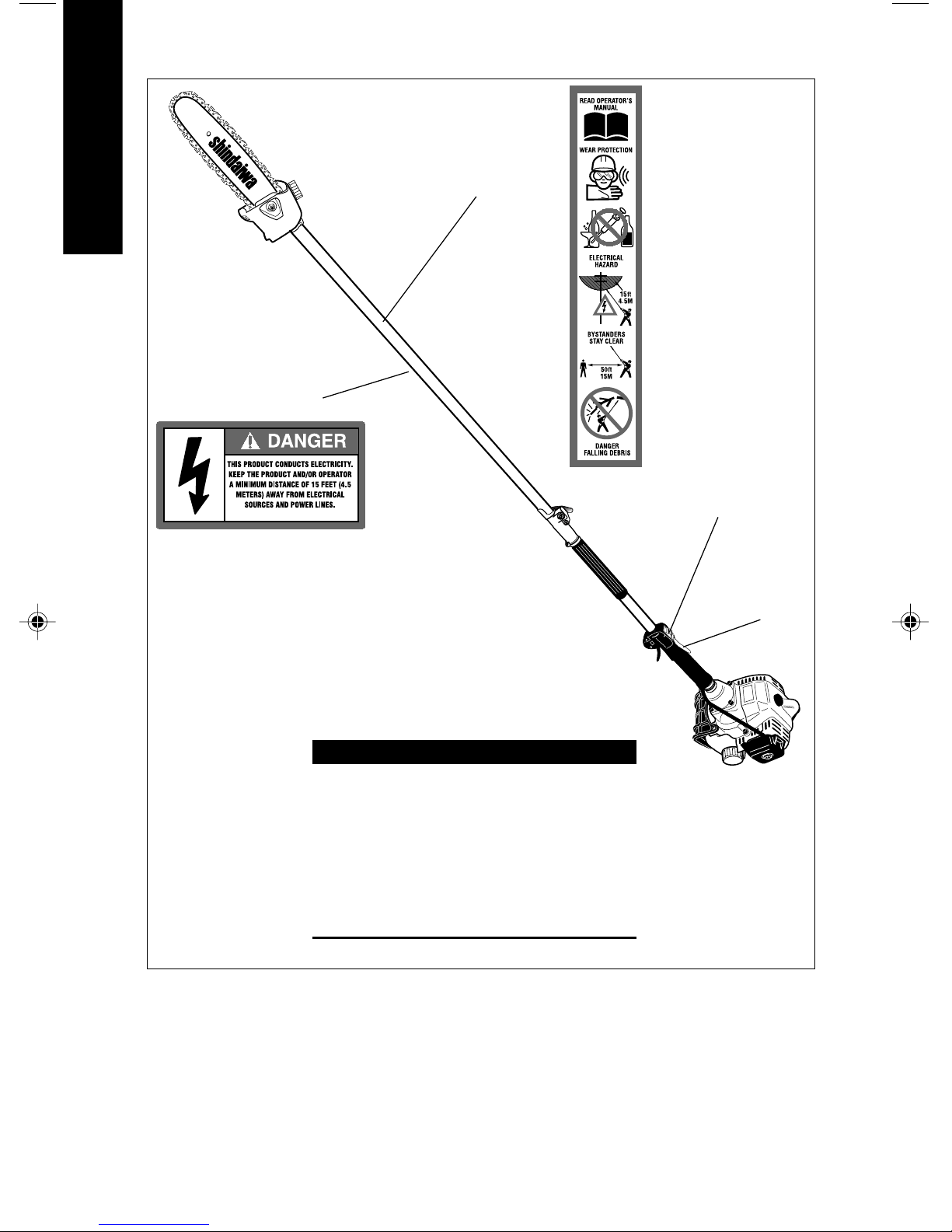
WARNING!
Use Good Judgement
SAFETY
WARNING!
Minimize the Risk of Fire
■NEVER smoke or light fires
near the unit.
■ALWAYS stop the engine and
allow it to cool before refuel-
ing. Avoid overfilling and wipe
off any fuel that may
have spilled.
■ALWAYS move the unit to a
place well away from a fuel
storage area or other readily
flammable materials before
starting the engine.
■ALWAYS inspect the unit for
fuel leaks before each use.
During each refill, check that no
fuel leaks from around the fuel
cap and/or fuel tank. If fuel leaks
are evident, stop using the unit
immediately. Fuel leaks must be
repaired before using the unit.
■NEVER place flammable
material close to the engine
muffler.
■NEVER run the engine without
the spark arrester screen in place.
P230_OM_62887-94011_01EC 8/18/05, 15:327