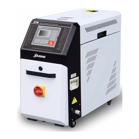
Shini STM-PW series User manual

STM-PW Series
Hi-Temp. WaterHeater
Date:Dec.2014
Version: Ver.B(English)


3(65)
Contents
1. General Description..................................................................................7
1.1 CodingPrinciple...................................................................................8
1.2 Feature.................................................................................................8
1.3 TechnicalSpecifications.....................................................................10
1.3.1 Specification............................................................................10
1.3.2 PumpPerformance..................................................................11
1.3.3 ReferenceFormulaofMouldControllersModelSelection.......11
1.4 SafetyRegulations.............................................................................12
1.4.1 SafetySignsand Labels..........................................................12
1.4.2 Signsand Labels.....................................................................13
1.4.3 OperationRegulations.............................................................14
1.4.4 Transportation andStorageoftheMachine.............................15
1.5 ExemptionClause..............................................................................17
2. StructureCharacteristics and WorkingPrinciple.................................18
2.1 WorkingPrinciple...............................................................................18
2.2 AssemblyDrawing.............................................................................19
2.2.1 AssemblyDrawing(STM-607-PW)..........................................19
2.2.2 PartsList (STM-607-PW).........................................................20
2.2.3 AssemblyDrawing(STM-1220-PW)........................................21
2.2.4 PartsList (STM-1220-PW).......................................................22
2.2.5 Pump.......................................................................................23
2.3 ElectricalDiagram..............................................................................24
2.3.1 MainCircuit (STM-PW)(400V).................................................24
2.3.2 ControlCircuit (STM-PW)(400V)............................................25
2.3.3 ElectricalComponentsLayout (STM-PW)(400V)...................26
2.3.4 ElectricalComponentsList (STM-PW)(400V).........................27
2.3.5 MainCircuit (STM-PW)(230V).................................................29
2.3.6 ControlCircuit (STM-PW)(230V)............................................30
2.3.7 ElectricalComponentsLayout (STM-PW)(230V)...................31
2.3.8 Thermocoupleand TerminalLayout (STM-PW)(230V)...........32
2.3.9 ElectricalComponentsList (STM-PW)(230V).........................33

4(65)
2.4 MainElectricalComponentsDescription............................................35
2.4.1 Overload Relay........................................................................35
2.5 OperationProcedures........................................................................36
2.5.1 Installation stepsforoptionswatermanifold(dewaxing)..........36
2.5.2 Installation stepsforoptionswatermanifold(welding).............36
3. Installation and Debugging.....................................................................38
3.1 Installation Space...............................................................................38
3.2 Mouldand WaterCoupling.................................................................38
3.3 PowerSupply.....................................................................................39
4. Operation Guide......................................................................................40
4.1 ControlPanel.....................................................................................40
4.2 Menu Introduction..............................................................................43
4.3 Machine Startup.................................................................................43
4.4 ParameterReferenceTable...............................................................52
4.5 Stop theMachine...............................................................................53
5. Trouble-shooting.....................................................................................55
6. Maintenance and Repair.........................................................................57
6.1 OpentheCovers................................................................................57
6.2 YType Strainer..................................................................................58
6.3 SolenoidValve...................................................................................59
6.4 Pipe Heater........................................................................................59
6.5 Printed Circuit Board..........................................................................60
6.6 DisplayerTerminalConnectingDiagram............................................63
6.7 MaintenanceSchedule.......................................................................64
6.7.1 About theMachine...................................................................64
6.7.2 Installation &Inspection...........................................................64
6.7.3 DailyChecking.........................................................................64
6.7.4 WeeklyChecking.....................................................................64
6.7.5 TrimonthlyChecking................................................................64
6.7.6 Half-yearlyChecking................................................................64
6.7.7 YearlyChecking.......................................................................65
6.7.8 3yearChecking.......................................................................65

5(65)
TableIndex
Table1-1 Specification...................................................................................10
Table2-1 PartsList (STM-607-PW)...............................................................20
Table2-1 PartsList (STM-1220-PW).............................................................22
Table2-3 ElectricalComponentsList (STM-607-PW)(400V)........................27
Table2-5 ElectricalComponentsList (STM-1220-PW)(400V)......................28
Table2-6 ElectricalComponentsList (STM-607-PW)(230V)........................33
Table2-8 ElectricalComponentsList (STM-1220-PW)(230V)......................34
PictureIndex
Picture1-1 PumpPerformance......................................................................11
Picture2-1 STM-PWWorkingPrinciple.........................................................18
Picture2-2 AssemblyDrawing(STM-607-PW)..............................................19
Picture2-2 AssemblyDrawing(STM-1220-PW)............................................21
Picture2-3 Pump...........................................................................................23
Picture2-4 MainCircuit (STM-PW)(400V)....................................................24
Picture2-5 ControlCircuit (STM-PW)(400V)................................................25
Picture2-6 ThermocoupleandTerminalLayout (STM-PW)(400V)...............26
Picture2-7 MainCircuit (STM-PW)(230V)....................................................29
Picture2-8 ControlCircuit (STM-PW)(230V)................................................30
Picture2-9 ElectricalComponentsLayout (STM-PW)(230V)........................31
Picture2-10 ThermocoupleandTerminalLayout (STM-PW)(230V).............32
Picture2-11 OverloadRelay..........................................................................35
Picture3-1 InstallationSpace........................................................................38
Picture3-2 MouldandWaterCouplings1......................................................38
Picture3-3 MouldandWaterCouplings2......................................................39
Picture3-4 MouldandWaterCouplings3......................................................39
Picture4-1 ControlPanel...............................................................................40
Pictute4-2 MenuOutline................................................................................43
Picture4-3: MainPowerSwitch........................................................................44
Picture4-4: InitialMenu....................................................................................44
Picture4-5: ControlSetting...............................................................................45
Picture4-6: AlarmSetting.................................................................................46

6(65)
Picture4-7: Output Setting...............................................................................47
Picture4-8:TemperatureSetting......................................................................48
Picture4-9:TimeSetting..................................................................................49
Picture4-10: Communication Setting...............................................................50
Picture4-11:Equipment Setting.......................................................................51
Picture4-12: OperationScreen........................................................................52
Picture6-1 Openthe Covers1.......................................................................57
Picture6-2 Openthe Covers2.......................................................................58
Picture6-3 Openthe Covers3.......................................................................58
Picture6-4 Y Type Strainer............................................................................58
Picture6-5 SolenoidValve.............................................................................59
Picture6-6 Pipe Heater1...............................................................................59
Picture6-7 Pipe Heater2...............................................................................59
Picture6-8 Pipe Heater3...............................................................................60

7(65)
1.General Description
Read thismanualcarefullybeforeoperationtopreventdamageofthe
machine orpersonalinjuries.
STM- PW/HPWserieshightemperaturewaterheaterareusedtoheat upthe
mouldand maintaintemperature,althoughtheycan beusedinothersimilar
applications. Hightemperaturewaterfromthemouldisreturned tothe cooling
tankandcooledbyeitherindirect cooling(Forhightemperaturemodels)ordirect
cooling(forstandardmodels). Itisthen pressurised bythehigh-pressurepump,
sent tothe heatingtankandfinallytothe mouldwithaconstanttemperature.The
HANYOUNG temperaturecontrollercanmaintainan accuracyof 0.5 .
Model: STM-607PW

8(65)
1.1CodingPrinciple
Notes*
D=Dual-heatingZonesPW=MediumisWaterwithHighTemp.
HPW=MediumisWaterwithHighTemperatureandHighPressure
CE=CE ConformityB=Buzzer
1.2Feature
1)Standardconfiguration
●Controlleradopts3.2" LCD foreasyoperation.
●Equippedwiththe designof7-dayautomaticstart/stop timer. LCD screen
can beconverted between ChineseandEnglish.Theunitoftemperature
can beconverted between oFand .
●P.I.D.multi-stagetemperaturecontrolsystemcan maintainamould
temperaturewithaccuracyof 0.5℃.
●Adoptshighefficiencywatercyclepump,whichcan meetthedemandsof
temperaturecontrolforprecisemouldsand mouldloop withminordiameter
toachieveprecisetemperaturecontroland highefficientheat exchange.
Pumpinsideadoptsstainless steeltoavoidexplosion.
●Multiplesafetydevicesincludingpowerreversephaseprotection, pump
overload protection, overheatprotectionandlowlevelprotection thatcan
automaticallydetectabnormalperformanceand indicatethisviavisible
alarm.
●WhileforSTM-PW,it can reach160.
●Equippedwithhighpressureprotection, safetypressurerelieving, automatic
watersupplyingand airexhausting.

9(65)
●STM-PWadoptsindirect cooling, whichmakestemperaturecontrolmore
precise.Thelowviscosityofwaterrealizesfast heat exchange.
●STM-PWseriesadoptsmagneticpumpwithstableperformanceand no
leakage, suitableforapplicationswhichneed longtimeheatingand
temperaturemaintaining.
2)Accessoryoption
●WatermanifoldsandTeflonhoseareoptional.
●RS485 communication functionisoptional.
●Displayofmouldtemperatureandmouldreturnwatertemperatureis
optional.
All serviceworkshouldbe carried out byaperson withtechnicaltrainingor
correspondingprofessionalexperience.The manualcontainsinstructionsforboth
handlingand servicing.Chapter6, whichcontainsserviceinstructionsintendedfor
serviceengineers. Otherchapterscontaininstructionsforthedailyoperator.
Anymodificationsofthemachinemustbe approved bySHINI inordertoavoid
personalinjuryand damagetomachine.Weshall not beliableforanydamage
causedbyunauthorized changeof themachine.
Ourcompanyprovidesexcellent after-salesservice. Shouldyou haveanyproblem
duringusingthemachine,pleasecontactthecompanyorthelocalvendor.
HeadquarterandTaipeifactory
Tel:(886)226809119
ShiniPlastics Technologies(Dongguan), Inc
Tel:(86)769 81116600
ShiniPlastics TechnologiesIndiaPvt.Ltd.
Tel:(91)250 3021166

10(65)
1.3Technical Specifications
1.3.1Specification
Table1-1 Specification
Tank(L)
Model Max.
temp.
Heater
(kw)
Pump (kw)
(50/60Hz)
Max.pump
flow (L/min)
(50/60Hz)
Max.pu
mp
pressure
(bar)
(50/60Hz)
Heating
chamber
number
Heat
ing
Cooli
ng
Coonling
method
Mould
coupling*
(inch)
Inlet /
Outlet
(inch)
Dimensions
(mm)
(H×W×D)
Weight
(kg)
STM-607PW
6 0.55 / 0.63
27 / 30 4.25 / 5.9
1 3.0
0.8
670×320×750
75
STM-1220PW
160℃
12 1.0 / 1.0
50 / 50.8
5.8 / 7.77
1 3.2
0.8
Indirect
3/8 (2×2)
3/4/ 3/4
670×320×900
80
Note: 1)"PW"standsforhigh temp. water heater,"HPW" standforwater Wereservetherighttochange
heater withhightemperatureandhighpressure,"*"standsforspecifications without priornotice.
options.
2)Toensurestablewater temperature,coolingwater pressureshould
notbelessthan2kgf/cm2,butalsono morethan5kgf/cm2.
3)Pumptestingstandard:Power of50/60Hz,purifiedwater at20℃.
(There is 10%toleranceforeithermax.flowrateormax.pressure ).
4)Power supply: 3Φ,230/400/460/575VAC, 50/60Hz.

11(65)
1.3.2PumpPerformance
Picture1-1 PumpPerformance
1.3.3ReferenceFormulaofMouldControllersModelSelection
HeaterPower(kW)=mouldweight (kg) ×mouldspecificheat (kcal/kg) ×
temperaturedifferencebetween mouldandenvironment() ×safetycoefficient
/ heatingduration / 860
Note: safetycoefficientcan selectavalue from1.3to1.5.
FlowRate(L/min)=heaterpower(kw) ×860 / [heatingmediumspecific
(kcal/kg) ×heatingmediumdensity(kg/L)×in/outlettemperaturedifference
()×time(60)]
Note:Waterspecificheat =1kcal/kg
Heatingmediumoil specificheat =0.49kcal/kg
Waterdensity=1kg/L
Heatingmediumoil density=0.842kg/L

12(65)
1.4SafetyRegulations
Strictlyabide bythe followingsafetyregulationstoprevent damageofthe
machine orpersonalinjuries.
1.4.1SafetySignsand Labels
Danger!
Theunit isdesigned toendurehightemp,andhighpressure. Forsafe
operation,do notremovethe coversorswitches.
Attention!
Theunit shouldbe operated byqualifiedpersonnelonly.
Duringoperation, avoidwearingglovesorclothesthatmaycause
danger.
Turnoff mainswitchwhen powersupplyisoff.
Stoptheunitwhentheremaybepowersupplyproblemscausedbystatic
electricity.
Put onsafetyglovesand shoesduringinstallation orrelocation.
Componentsfromourcompanycan onlybe used forreplacement.
Warning!
Donottouchthe switchwithwet object orhands.
Donotusethemachinebeforefullyawareofitsperformance.
Becarefulnot totouchorhit the switchorsensor.
Pleasekeepenoughoperationspace,andkeep awayobstacles.
Toavoidproducingstatics, cleanthefloorfromoil orwatertokeep adry
environment.
Protectthemachineagainst severevibration orcollision.
Donotremovesafetysignsormakeit dirty.
Drunken,medicine-taking, ormen withoutproperjudgement shouldnot
operatethe machine.
Warning!
Hightemperature, takecareof hands! Thislabelisattached on the
surfaceofheatingparts.

13(65)
1.4.2Signsand Labels
Regularlyclean the filterscreen in
the copperscrewtoavoidblockage
and aswell ensurean excellent
workingperformance.
Thisistoindicatemotorrotating
direction.Whenphasereversal
happens,thealarmsoundsand
indicatoron controlpanelwill
indicate.
Pleaseexchangethe placeof twoof
the electricalwirestosolvethis
problem.
Highvoltage! Electricalshock may
happen.Carefulness isrequired from
the operator.
Attentions!
Thisisgeneralwarningswhich
operatorsshouldpayattention to.
Frommould: connectorfor
circulatingwater/oil comingfrom
mould.
Pumppressuremeter:indicating
actualpressureofsystem.
Tomold: connectorforcirculating
water/ oil togotomould.

14(65)
1.Tomaintaintemperature
consistency, coolingwater
pressuremustbehigherthan2
baratall time,but shouldnever
exceed 5barinanycase.
2. CleanY-shape CoolingWater
Strainerperiodicallytoensure
perfect coolingcapacity.
Waterinlet: inletforreplenishing
waterand coolingwater.
Wateroutlet: drainageoutlet.
Pleaseabide bythe safetyguide when you operatethemachinesoastoprevent
damageof themachineandpersonalinjuries.
All electricalcomponentsshouldbe installedbyqualified electricians. Turn
offmainswitchand controlswitchduringrepair and maintenance.
Warning! Highvoltage!
Thismarkisattachedonthecoverofthe controlbox.
Warning! Becareful!
Be morecarefulwhen thismarkappears.
1.4.3OperationRegulations
1)Beforeoperation,makesurethat coolingwateriscleansoft waterwithout
pollutants.
※Lowqualitywaterbringslimescales,whichmaycauseproblems.
2)Ifproblemsof drainageorbadtemperaturecontrolarenoted,pleaseclean
solenoidvalveand coolingwaterinlet and outlet.
3)Donotmovetheunit when it isinoperation.
4)Wheninneed ofrepairing, wait until oil temperaturefallsbelow30 .
5)Motoroverload maybe causedbyphaseshortage,pipe obstruction,broken

15(65)
bearing, etc. Motoroverload relaywilltripofftostopthemachine when this
happens.Fixingthe problems, pressRESETon overloadrelaytoclearthe
alarm.
6)Beforeturnoff thepump, wait until oil temperaturefallsblow50 .Orthelife
oftheunit wouldbeaffected.
7)Ifthe settingtemperatureisbelow100℃, then thepressureswitchsetting
value shouldbe1.5-2bar;Ifthesettingtemperaturesetsbetween100℃and
200℃,then the recommendablepressureswitchsettingvalue shouldbe2.8
bar. If thecoolingwaterpressureistoo low, then thepressureswitchsetting
value can beadjusted properlytoensurenormalrunning. However,it may
affectthelimitation ofsettingtemperatureorcauseunstabletemperature
control.
8)Pleaseconnectthecoolngwateroutlet withhightemperatureresistantpipe
when temperatureisabove100℃.
1.4.4Transportation andStorageoftheMachine
Transportation
1)STM-PWseriesstandardoil heaterarepacked incratesorplywood cases
withwooden palletat the bottom,suitableforquick positioningbyforklift.
2)Afterunpacked, castorsequipped on the machinecan be usedforeaseof
movement.
3)Donot rotatethemachineandavoidcollision withotherobjectsduring
transportationtoprevent improperfunctioning.
4)The structureofthe machine iswell-balanced,althoughit shouldalsobe
handled withcarewhenliftingthemachineforfearoffallingdown.
5)The machine anditsattachedpartscanbekeptat atemperaturefrom-25℃
to+55 forlongdistancetransportationandforashort distance, itcan be
transported withtemperatureunder+70 .
Storage
1)STM-PWseriesstandardoil heatershouldbe stored indoorswith
temperaturekeptfrom5 to40 andhumiditybelow80%.
2)Disconnect all powersupplyand turnoffmainswitchand controlswitch.
3)Keepthe wholemachine,especiallythe electricalcomponentsawayfrom

16(65)
watertoavoidpotentialtroublescaused bythe water.
4)Plasticfilm shouldbeusedtoprotect the machinefromdust and rains.
Workingenvironment
Themachineshouldbeoperated:
1)Indoorsinadryenvironment withmaximumtemperature+45 and humidity
notmorethan 80%.
Donotusethemachine:
1)Ifit iswithadamaged cord.
2)Onawet floororwhen it isexposed toraintoavoidelectricalshock.
3)Ifithasbeendropped ordamaged until it ischeckedorfixed byaqualified
serviceman.
4)Thisequipmentworks normallyintheenvironmentwithaltitudewithin3000m.
5)At least aclearanceof1msurroundingthe equipment isrequired during
operation.Keepthisequipment awayfromflammablesourcesat least two
meters.
6)Avoidvibration, magneticdisturbanceat theoperationarea.
Rejectedpartsdisposal
When the equipmenthasrun out itslifetimeand can notbe usedanymore,
unplugthepowersupplyand disposeof it properlyaccordingtolocalcode.
FireHazard
Incaseoffire, Co2drypowderfireextinguishershouldbe applied.
Pleaseabidebythesafetyguide when you operatethemachinesoasto
prevent damageofthemachine andpersonalinjuries.
All electricalcomponentsshouldbe installedbyqualified electricians.
Turnoff mainswitchand controlswitchduring repair and maintenance.
Warning! Highvoltage!

17(65)
Thismarkisattachedon the coverof thecontrolbox.
Warning! Becareful!
Be morecarefulwhen thismarkappears.
Warning!
Hightemperature, takecareof hands! Thislabelisattached on the
surfaceofheatingparts.
1.5 Exemption Clause
Thefollowingstatementsclarifytheresponsibilitiesandregulationsbornbyany
buyeroruserwho purchasesproductsandaccessoriesfromShini(including
employeesandagents).
Shiniisexempted fromliabilityforanycosts,fees,claimsandlossescausedby
reasonsbelow:
1. Anycarelessorman-madeinstallations,operation andmaintenancesupon
machineswithoutreferringtothe Manualpriortomachineusing.
2. Anyincidentsbeyondhumanreasonablecontrols, whichincludeman-made
viciousordeliberatedamagesorabnormalpower,and machine faultscaused
byirresistiblenaturaldisastersincludingfire,flood,stormand earthquake.
3. Anyoperationalactionsthatarenotauthorized byShiniuponmachine,
includingaddingorreplacingaccessories, dismantling,deliveringorrepairing.
4. Employingconsumablesoroil mediathatarenotappointed byShini.

18(65)
2. Structure Characteristics andWorkingPrinciple
2.1WorkingPrinciple
Picture2-1 STM-PWWorkingPrinciple
Thehightemperaturewaterfromthemoldreturnstothepumpinlet fromthe
pipeline,then be pressurized bythe pumpandconveyed totheheaterand
againbe heatedand returnstothe mold.Thelooprepeats.Inthisprocess,
when liquidlevelswitchdetectstheliquidlevellowerstotheset value and the
machine will sound an alarmandhalt.Ifthetemperatureofthe waterexceeds
the set value,thesystemwill automaticallystart the solenoidvalvetolet the
coolingwatercomeintothedoublepipesstructureof theheatingtankandcool
downthe water, thenaconstanttemperaturecan bemaintained. If the
temperaturestill maintainshightotheEGO set value,the systemwillsoundan
alarmandhalt;when systempressureexceedsset valvue ofhighpressure
switch, machinehaltsand soundanalarm.Ifthe pressurecontinuesrisingto
the set value ofthe safetyvalve, the safetyvalvestartstodecompress the
system.

19(65)
2.2AssemblyDrawing
2.2.1AssemblyDrawing(STM-607-PW)
Remarks:Please refertomateriallist2.2.2forspecificexplanation ofthe Arabicnumbersin
partsdrawing.
Picture2-2 AssemblyDrawing (STM-607-PW)

20(65)
2.2.2PartsList (STM-607-PW)
Table2-1 PartsList (STM-607-PW)
No.
Name Part No. No.
Name Part No.
1
Control box - 24 PumpMP-55 YW64080600000
2
Door plate- 25 EGO assembly BH90115000050
3
Door platealuminum
handle6609 YW20660900100
26 Lentil-headedscrewM5×10 YW62051000100
4
Baseplateofcontrol
box - 27 Line clampfixing plate -
5
Thick head screw
M6×20 YW63062000000
28 Big hinge CL219-1 YW06219100000
6
Caster2" YW03000200000
29 Inner hexagon screwM8×20 YW61082000200
7
HAN YOUNGcontroller
MT100-01 YE81100010000
30 Spring gasket8mm YW65008000100
8
Pressuregauge0-15kg
YW85015000000
31 Returnpipe parts -
9
Pressuregaugepipe - 32 High pressurepipe -
10
Teflon pipe with
connector 3/8"×60cm YW59386000000
33 Filling water pipe-
11
Cover plate- 34 Lowpressureon-off controller
0-0.8MPa YE90000800000
12
Lowpressurepipe - 35 Hot water by-passpipe -
13
Heatingtankparts- 36 Filling pipeconnectorparts -
14
Coolingwater inlet pipe
- 37 Coolingwater by-passpipe -
15
Water drainage pipe - 38 Water drainage pipeparts -
16
Ytype filteringwater
valve1/2"YW57010200000
39 Side plate -
17
Coppercore
M13×1/2PT BH12131200010
40 Inner hexagon screwM10×30
YW61103000100
18
Lentil-headedscrew
M6*10 YW62061000000
41 Spring gasket10 YW65010000000
19
Flat gasket
8×22×1.5mm YW66082200000
42 Flat gasket10.5×20×2mm YW66102000100
20
Spring gasket6 YW65006000100
43 ButterflyscrewM8×15 YW69081500000
21
Flat gasket6×18×1.0 YW66061800000
44 Spring gasket8×16×1.5mm YW66081600000
*means possiblebrokenparts. ** means easybroken part. and sparebackupissuggested.
Please confirmthe versionofmanualbeforeplacingthe purchaseordertoguarantee thatthe
itemnumber ofthe sparepart isinaccordancewiththe realobject.
Other manuals for STM-PW series
2
This manual suits for next models
3
Table of contents
Other Shini Water Heater manuals
Popular Water Heater manuals by other brands

Toyotomi
Toyotomi Oil Miser OM-148 (Type D) Operation and maintenance instructions

Marey
Marey ECO180 instruction manual

GE
GE GG50T06PVT Energy guide

Hubbell
Hubbell ST Operating and maintenance manual

STIEBEL ELTRON
STIEBEL ELTRON UFP 5 h Operating and installation instructions

Jocel
Jocel JTDSZF20LJ-80L instruction manual