Shivaki SZTV-24LED4 User manual

SERVICE MANUAL
SZTV-24LED4/3MS663M0T2A
1. Caution…………………………………………………………………………
2. specification……………………………………………………………………
3. Alignment Procedure…………………………………………………………
4.Block diagram…………………………………………………………………
5.Scheme Diagram ……………………………………………………………
6. Troubleshooting………………………………………………………………
([SORGHGUDZLQJ
This manual is the latest at the time of printing, and does not
include the modification which may be made after the printing, by
the constant improvement of product
CA UTION: TO RE DUCE THE RIS K OF
ELECTR ICA L SHOCK, DO NOT RE MOVE
COVER (OR BACK). NO USER SERVICEABLE
PAR TS INSIDE . RE FE R SER VIC ING TO
QUALIFIED SERVICE PERSONNEL.
The lighting flash with arrowhead symbol, with an equilateral triangle is intended to
alert the user to the presence of uninsulated voltage within the products
enclosure that may be of sufficient magnitude to constitute a risk of electric shock to
the person.
The exclamation point within an equilateral triangle is intended to alert the user to the
presence of important operating and maintenance (servicing) instructions in the
literature accompanying the appliance.
CAUTION:
Use of controls, adjustments or procedures other than those specified herein may result in
hazardous radiation exposure.
CA U T ION
RISK
RISK OF
ELECTRI
ELECTRIC
SHOCK
SHOCK DO
NOT
NOT
OPEN.
OPEN.
2
dangerous
WARNING: TO REDUCE RISK OF FIRE OR ELECTRIC SHOCK, DO NOT
EXPOSE THIS APPLIANCE TO RAIN OR MOISTURE.
SCHNEIDER ELECTRONICS GMBH-GERMANY
1. CAUTION

1. When the power cord or plug is damaged or frayed, unplug this television set from the wall outlet and refer servicing to
qualified service personnel.
2. Do not overload wall outlets and extension cords as this can result in fire or electric shock.
3. Do not allow anything to rest on or roll over the power cord, and do not place the TV where power cord is subject to
traffic or abuse. This may result in a shock or fire hazard.
4. Do not attempt to service this television set yourself as opening or removing covers may expose you to dangerous
voltage or other hazards. Refer all servicing to qualified service personnel.
5. Never push objects of any kind into this television set through cabinet slots as they may touch dangerous voltage
points or short out parts that could result in a fire or electric shock. Never spill liquid of any kind on the television set.
6. If the television set has been dropped or the cabinet has been damaged, unplug this television set from the wall outlet
and refer servicing to qualified service personnel.
7. If liquid has been spilled into the television set, unplug this television set from the wall outlet and refer servicing to
qualified service personnel.
8. Do not subject your television set to impact of any kind. Be particularly careful not to damage the picture tube surface.
9. Unplug this television set from the wall outlet before cleaning. Do not use liquid cleaners or aerosol cleaners. Use a
damp cloth for cleaning.
10.1. Do not place this television set on an unstable cart, stand, or table. The television set may fall, causing serious injury
to a child or an adult, and serious damage to the appliance. Use only with a cart or stand recommended by the
manufacturer, or sold with the television set. Wall or shelf mounting should follow the manufacturer s instructions, and
should use a mounting kit approved by the manufacturer.
10.2. An appliance and cart combination should be moved with care. Quick stops, excessive force, and uneven surfaces
may cause the appliance and cart combination to overturn.
CAUTION:
Read all of these instructions. Sa ve these instructions for later use . Follo w all W arnings and
Instructions marked on the audio equipment.
1. Read Instructions-All the safety and operatinginstructionsshouldbe read before the productis operated.
2. Retain Instructions- The safety and operating instructions should be retained for future reference.
3. Heed Warnings- All warnings on the product and in the operating instructions should be adhered to.
4. Follow Instructions- All operating and use instructions should be followed.
3
SCHNEIDER ELECTRONICS GMBH-GERMANY
IMPORTANT SAFETY INSTRUCTIONS
FOR YOUR PERSONAL SAFETY

11. Do not use this television set near water ... for example, near a bathtub, washbowl, kitchen sink, or laundry tub, in a
wet basement, or near a swimming pool, etc.
Never expose the set to rain or water. If the set has been exposed to rain or water, unplug the set from the wall
outlet and refer servicing to qualified service personnel.
12. Choose a place where light (artificial or sunlight) does not shine directly on the screen.
13. Avoid dusty places, since piling up of dust inside TV chassis may cause failure of the set when high humidity persists.
14. The set has slots, or openings in the cabinet for ventilation purposes, to provide reliable operation of the receiver, to
protect it from overheating. These openings must not be blocked or covered.
Never cover the slots or openings with cloth or other material.
Never block the bottom ventilation slots of the set by placing it on a bed, sofa, rug, etc.
Never place the set near or over a radiator or heat register.
Never place the set in enclosure, unless proper ventilation is provided.
15.1. If an outside antenna is connected to the television set, be sure the antenna system is grounded so as to provide some
protection against voltage surges and built up static charges, Section 810 of the National Electrical Code, NFPA No.
70-1975, provides information with respect to proper grounding of the mast and supportingstructure, grounding of the
lead-in wire to an antenna discharge unit, size of grounding conductors, location of antenna discharge unit, connection
to grounding electrode, and requirements for the grounding electrode.
15.2. Note to CATV system installer : (Only for the television set with CATV reception)
This reminder is provided to call the CATV system attention to Article 820-40 of the NEC that provides
guidelines for proper grounding and, in particular, specifies that the cable ground shall be connected to the grounding
system of the building, as close to the point of cable entry as practical.
16. An outside antenna system should not be located in the vicinity of overhead power lines or other electric lights or power
circuits, or where it can fall into such power lines or circuits. When installing an outside antenna system, extreme care
should be taken to keep from touching such power lines or circuits as contact with them might be fatal.
17. For added protection for this television set during a lightning storm, or when it is left unattended and unused for long
periods of time, unplug it from the wall outlet and disconnect the antenna. This will prevent damage due to lightning
and power-line surges.
ANTENNA
LEAD- IN WIRE
ANTENNA DISCHARGE
UNIT (NEC SECTION
810-20)
GROUNDING
CONDUCTORS
(NEC SECTION810-21)
GROUND CLAMPS
POWER SERVICE GROUNDING
ELECTRODE SYSTEM
(NEC ART 250. PART H)
ELECTRIC SERVICE
EQUIPMENT
GROUND CLAMP
NEC-NATIONAL ELECTRICAL CODE
EXAMPLE OF ANTENNA GROUNDING AS PER
NATIONAL ELECTRICAL CODE
EXAMPLE OF ANTENNA GROUNDING AS PER NATIONAL ELECTRICAL CODE INSTRUCTIONS
a built-in
installer s
4
SCHNEIDER ELECTRONICS GMBH-GERMANY
PROTECTION AND LOCATION OF YOUR SET
PROTECTION AND LOCATION OF YOUR SET

18.
This television set should be operated only from the type of power source indicated on the marking label.If you are not
sure of the type of power supply at your home, consult your television dealer or local power company. For television
sets designed to operate from battery power, refer to the operating instructions.
19. If the television set does not operate normally by following the operating instructions, unplug this television set from the
wall outlet and refer servicing to qualified service personnel. Adjust only those controls that are covered in the operating
instructions as improper adjustment of other controls may result in damage and will often require extensive work by a
qualified technician to restore the television set to normal operation.
20. When going on a holiday : If your television set is to remain unused for a period of time, for instance, when you go on
a holiday, turn the television set and unplug the television set from the wall outlet.
21. If you are unable to restore normal operation by following the detailedprocedurein your operating instructions,
do not attempt any further adjustment. Unplug the set and call your dealer or service technician.
22. Whenever the television set is damaged or fails, or a distinct change in performance indicates a need for
service, unplug the set and have it checked by a professional service technician.
23. It is normal for some TV sets to make occasional snapping or popping sounds, particularly when being
turned on or off. If the snapping or popping is continuous or frequent, unplug the set and consult your
dealer or service technician.
24. Do not use attachments not recommendedby the television set manufacturer as they may cause hazards.
25. When replacementparts are required, be sure the service technicianhas used replacementparts specified
by the manufacturer that have the same characteristics as the original part. Unauthorized substitutions
may result in fire, electric shock, or other hazards.
26. Upon completion of any service or repairs to the television set, ask the service technician to perform
routine safety checks to determine that the television is in safe operating condition.
off
5
SCHNEIDER ELECTRONICS GMBH-GERMANY
OPERATION OF YOUR SET
IF THE SET DOES NOT OPERATE PROPERLY
FOR SERVICE AND MODIFICATION

LCD TV SPECIFICATION RELEASE
Version: V1.0 Issued Date: 2019.04.30
Brand: Model No.:
FORM VERSION: V1
PICTURE
Panel Size (inch) 24"
Category LCD TV
Aspect Ratio 16:9
Color Temperature Cold/Normal/Warm SIGNAL FORMAT CAPABILITY
Backlight Adjustable Yes Component Video Format N/A
Scaler Mode Auto/4:3/16:9/Zoom1/Zoom2 DVI Video Format Up to XGA for HDMI-PC
Picture Mode Dynamic/Standard/Mild/Personal HDMI Video Format Up to 1080P
Film Mode (3:2 pull down) No PC Compatibility N/A
Picture Enhancement TERMINALS
Comb Filter 3D Audio/CVBS Input (Composite) 1 (Mini, with Mini Adapter)
Dynamic Niose Reduction Yes S-Video Input X
Adaptive Deinterlacing Yes Audio Input for S-Video X
Blue Stretch No YPbPr Input X
Black Stretch No Audio Input for YPbPr X
Motion Compensation No YCbCr Input X
DLTI No Audio Input for YCbCr X
DCTI No VGA Input(RGB) X
Dynamic Skin Correction No Audio Input for RGB X
Panel Specification HDMI 1.4a 1
Back Light Unit D-LED HDMI 2.0 X
Panel supplier INX CEC for HDMI Yes
Panel size 23.6" ARC for HDMI 1 (for HDMI)
Display Resolution 1366*768 MHL X
TV Brightness (cd/m2) 180 (typ.) Audio/CVBS Output (Composite) X
TV Brightness (cd/m2) 165 (min.) SPDIF 1 (Coaxial)
Brightness Uniformity@9 Points ≥60% Headphone Output 1
Contrast Ratio 3000:1 (typ.) RF Input(Antenna) 1(1 ANALOG & DVB-T2/T/C)
Response Time 8.5mS (typ.) CI SLOT 1 (CI+)
Viewing Angle (H/V) 178/178 (typ.) USB 2.0 1
Life Time 30000H USB 3.0 X
Display Colors 16.7M SCART X
Frame Rate (2D) 60Hz RJ45 X
SOUND
Speakers Integrated speakers (Bottom side) Basic Info.
Audio Power Output 3W+3W ATV Video System PAL, SECAM
Sound Features AV Stereo ATV Audio System BG, DK, I, L/L’,MN, NICAM/A2
Sound Mode Standard/Music/Movie/Sports/Personal DTV System DVB-T2/T/C
AVC (Auto Volume Control) Yes AV System PAL, NTSC, SECAM
Sound Control Bass, Treble, Balance Channels(analog) 99
DD (Dolby Digital) DD+ (Need Lisence) DTV Channels(digital) 700
Surround Sound No Chassis MS3663 3IN1
FUNCTION Certification & Regulation N/A
Lock Yes Power Supply AC 180-240V 50/60Hz
CCD (Closed Caption) X Energy Efficiency Level N/A
EPG Yes(at DTV) Power Consumption-TV on TBD
Subtitle Yes(at DTV) Power Consumption-Standby ≤0.5W
LCN Yes(at DTV) Default Color of Front Cabinet Black
Parental Control Yes(at DTV) LOGO Type of Front Cabinet Silk Printing
Clock/Timers Yes Keyboard Position Bottom-Center
Teletext Yes (1000 pages) Base Stand Detachable Yes
NICAM Yes Unpackaged Dimension for Main Body (L*H*D) (mm)
PVR / Time Shift Yes With Base Stand (mm) TBD
Audio Language Yes Without Base Stand (mm) TBD
OSD Features Common UI Packaged Dimension (L*H*D)
Main Body (mm) TBD
Speaker Box N/A
Base Stand N/A
Software Upgrade Yes(By USB) Net Weight (Kg) TBD
Game X Gross Weight (Kg) TBD
Hotel Yes Container Loading
Demo Mode (E-sticker) X 20 feet TBD
Power on LOGO Yes 40 feet TBD
Other Functions 40 feet high TBD
CONNECTIVITY ACCESSORIES
WiFi No
DLNA No
Blue Tooth No Remote Control Mode RC200 (with 7# batteries)
WiDi No Base Stand Integrated Packaging
Mirrorcast No Speaker Box Integrated
USB Connection Movie/Music/Photo Wall Mount Optional
Movie Supported File Format AVI/MKV/MP4/TS/VOB/MPG/DAT Others
Movie Supported Video Codec H.265/H.264/MPEG1/MPEG2/MPEG4/XviD/VC1 LICENSES
Movie Supported Audio Codec AC3/MP3/AAC/LPCM
Music Supported Format MP3/AAC/LPCM
Photo Supported Format JPG/JPEG
Before your signature, Please check all items (special yellow part) and give your feedback if any modification and request.
Drafted by: Customer Confirmed by:
English
IP fee need to be paid to patent owner by Brand
Company
Model: 24D1200 HD MS3663 DVB-T2/T/C
OSD Language English, Russian
Operation Manual Language
Licenses

MT5659 Commissioning Manual
1.Enter the factory menu mode (design mode)
1.1Press the menu and then the cursor on the contrast item, press 1950 into the
factory design mode menu.
Design mode menu:
DesignMode Hotkey : Press the left and right keys to turn the design mode on or off
Factory Menu : Press the left and right keys to enter the factory mode menu
Shop Setting : Press the left and right keys to enter the shop setting menu
Other : Press the left and right keys to enter other plant items, used as serial
port switch or some other factory adaptability function entry
Service Menu : Press the left and right keys to enter the aftermarket mode menu
Hotel Menu : Press the left and right keys to enter the hotel menu
SW NO : Software version number
Project NAME : Model name
Date : Software compilation time
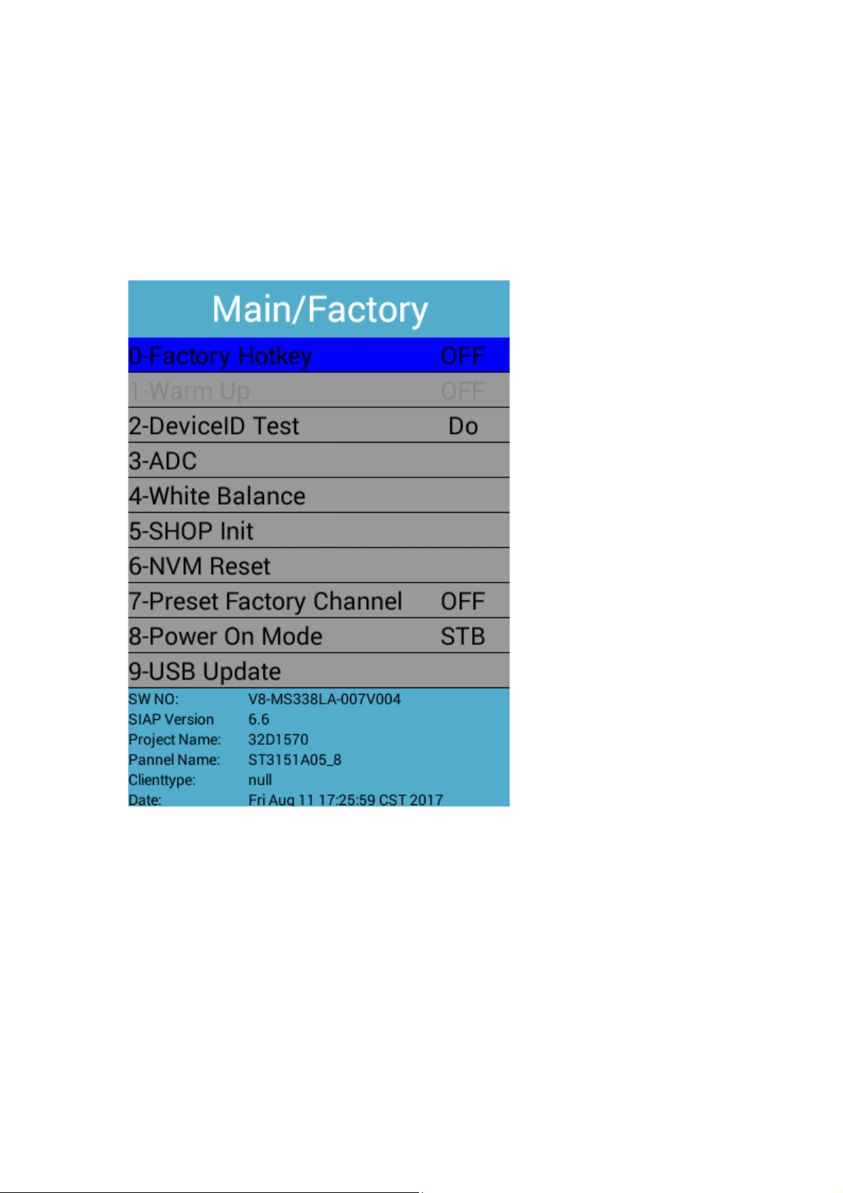
2.Enter the factory menu mode (factory mode)
From the factory menu of the design mode, press or press menu to place the cursor
on the contrast item and press 9735 to enter the factory mode menu.
Factory mode menu:
Factory Hotkey : Factory mode switch
WARM-UP : Press the left and right keys to enter the aging mode
ADC : Press the left and right keys to enter the ADC calibration page
White Balance : Press the left and right keys to enter the white balance adjustment
page
SHOP Init : Press the left and right keys to reset the factory (not including white
balance data and ADC data)
NVM Reset : Press the left and right keys to perform NVM reset (enter TCL factory
mode, not including white balance data and ADC data)
Preset Factory CH : Press the left and right keys to preset the factory channel of
TCL
PowerOn Mode : Press the left and right keys to set the power on mode

3.White Balance Adjustment Page:
Source : Press the left and right keys to select the channel that needs to adjust
the white balance
Color Temp : Press the left and right keys to adjust the color temperature mode
R-Gain : Press the left and right keys to adjust the R-Gain value
G-Gain : Press the left and right keys to adjust the G-Gain value
B-Gain : Press the left and right keys to adjust the B-Gain value
R-Offset : Press the left and right keys to adjust R-Offset value
G-Offset : Press the left and right keys to adjust G-Offset value
B-Offset : Press the left and right keys to adjust B-Offset value
White Balance Init : Press the left and right keys to initialize the white balance
data
4.Factory OTHER menu:
From the factory menu of the design mode, go to the factory OTHER menu.
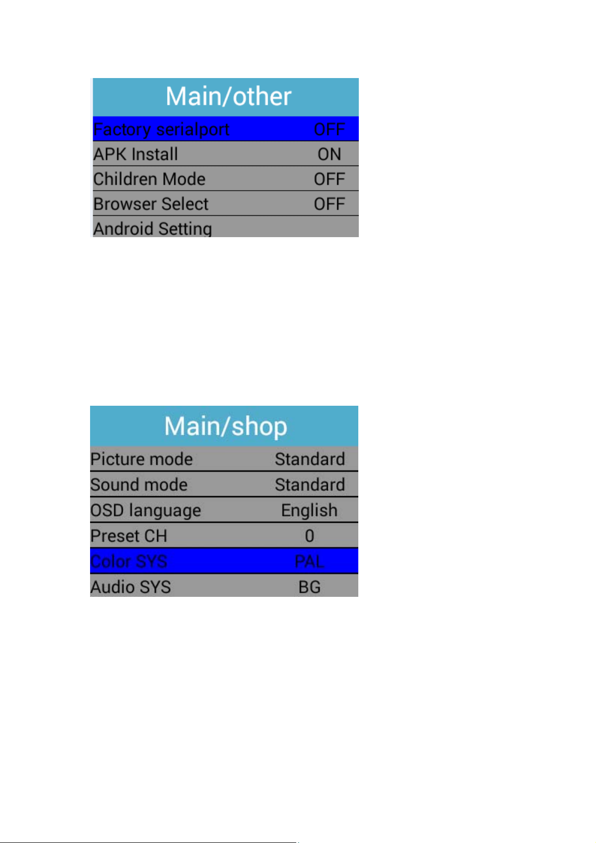
Factory seialport : Press the left and right keys to turn the serial port on or off
APK Install : Left and right keys to switch whether the apk can be installed
Children Mode: Left and right keys to switch child lock
Browser Select:Browser selection
5.Enter the shop menu
From the design mode of the factory menu to enter or press the menu and then place
the cursor on the contrast item, press 9715 into the hotel menu.
shop menu:
Picture mode : Default Picture mode switch
Sound mode : Default Sound mode switch
OSD language : Default language setting
Preset CH : Power on default channel settings
Color SYS : Power on Color SYS settings
Audio SYS: Power on Audio SYS settings

6.Upgrade
1,beforetheupgrade:
A.ConfirmthattheUdiskformatisFAT32beforeupgrading
B.UpgradeBINfileincludesMbootandmainprogrambydefault(unlessotherwisespecified)
2,ACpowerupgrade
UnzipthefiletotheUdiskandmakesurethattheUdiskonlyhasthisoneupgradefile
B.InserttheUSBdiskintotheUSBport(inordertoensurethestabilityoftheupgrade,otherUSB
portdonotinsertanyequipment)
C.ACpoweron,thesystemwillautomaticallyentertheupgrademode
D.Upgrade,youcanusetheLEDlightstodeterminetheupgradestatus,thewholeprocessis
about3minutes.
LEDslowflash:thatisbeingupgraded;
LEDflash:thatupgradeiscompleted,thenre‐powerontheboot;
Note:Thesamesoftwarecannotbeupgradedautomaticallyagain.
5
5
4
4
3
3
2
2
1
1
D D
C C
B B
A A
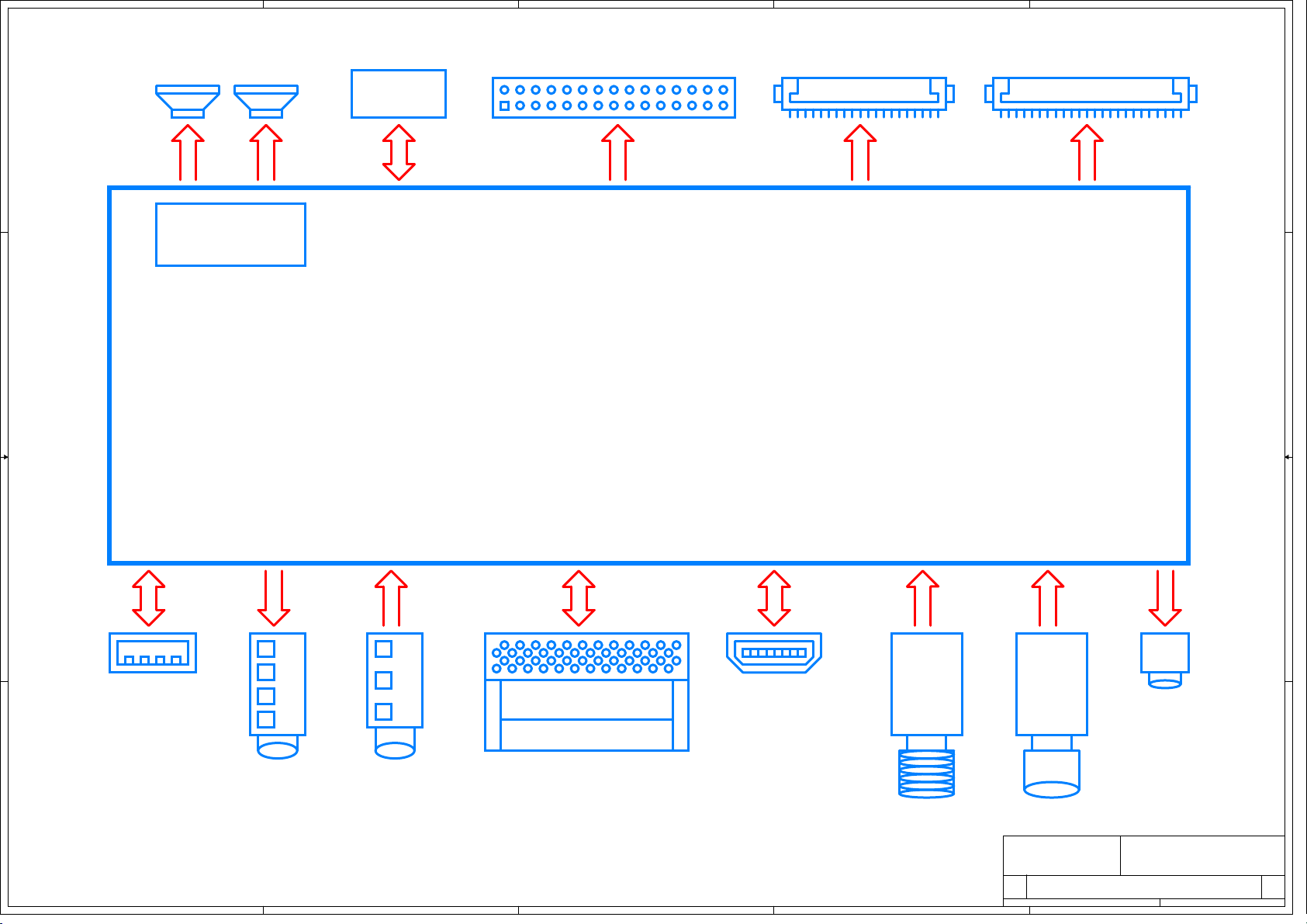
3663
HDMI
IEC‐RF
30PINDIP
SPEARK
2*8R*8W
CLASSD
RDA3118e
8MFLASH
COAX
EarPhone
USB2.0
F‐RF
PCMCIA
51PINFFC30PINFFC
Mini_AVIN
Title
Size Document Number Rev
Date: Sheet of
BLOCKDIAGRAM
11
CV3663LL-A24
A3 112Monday, July 23, 2018
Title
Size Document Number Rev
Date: Sheet of
BLOCKDIAGRAM
11
CV3663LL-A24
A3 112Monday, July 23, 2018
Title
Size Document Number Rev
Date: Sheet of
BLOCKDIAGRAM
11
CV3663LL-A24
A3 112Monday, July 23, 2018

5
5
4
4
3
3
2
2
1
1
D D
C C
B B
A A
POWERTREE
12V_EN
PWR_ON/OFF
220mA
+12VU
5V_EN
GV3407
PANEL-ON/OFF
PANEL
VCC_PANEL
1000mA
RDA3118E
AMP
JW5060T
AMPPOWER
+5V_STB
LNB-EN
JW4005 LNB
5V_SW
1.1V_VDDC
5V_USB
1220mA
350mA 36633.3V
1117_3.3
3.3V_TUNER
1.5V_DDR
3.3V_STB
2500mA
600mA
LNBPOWER
R842:220mA
5815:155mA
1000mA USB
TUNER
36631.5V
36631.1V
2000mA
430mA
1117_3.3
DC2DC1A
TLV62569
350mA
SY6280
500mA
1027mA
1000mA
2500mA
600mA
150mA
PWR_ON/OFF
GV3407
PANEL-ON/OFF
Title
Size Document Number Rev
Date: Sheet of
POWERTREE-3663
11
CV3663LL-A24
A3 212Monday, July 23, 2018
Title
Size Document Number Rev
Date: Sheet of
POWERTREE-3663
11
CV3663LL-A24
A3 212Monday, July 23, 2018
Title
Size Document Number Rev
Date: Sheet of
POWERTREE-3663
11
CV3663LL-A24
A3 212Monday, July 23, 2018

5
5
4
4
3
3
2
2
1
1
D D
C C
B B
A A
+12V_STBTO+5V_STB
Vout=0.765*(1+R1/R2)
R2
R1
Vout=0.6*(1+R1/R2)
R2
R1
+5V_STBTO+1.15V_VDDC
Vout=0.6*(1+R1/R2)
R2
R1
+5V_STBTO+1.5V_DDR +5V_STBTO+3.3V_STB
+5V_STBTO+5V_USB
L:POWEROFF
H:POWERON
Iout=6800/R1
R1
+5V_USB
+5V_STB
+3.3V_STB
+12V_STB +5V_STB +1.15V_VDDC
+5V_STB
+1.5V_DDR
+5V_STB
+5V_STB
12VU
PWR-ON/OFF
PWR-ON/OFF
Title
Size Document Number Rev
Date: Sheet of
MAINCHIP-POWER
11
CV3663LH-B42
A3 312Monday, July 23, 2018
Title
Size Document Number Rev
Date: Sheet of
MAINCHIP-POWER
11
CV3663LH-B42
A3 312Monday, July 23, 2018
Title
Size Document Number Rev
Date: Sheet of
MAINCHIP-POWER
11
CV3663LH-B42
A3 312Monday, July 23, 2018
RD10
12K_1%
RD5
NC
RD15
10R
NC
A6
AHOLE138U
1
TP2 +1.15V_VDDC
1
RD6
12K_1%
CD35
NCCD10
10uF/6.3V
+
EC1
NC/220uF/16V
CD30
100nF/16V
RD1 100K
M3
orientpad
1
CD9
100nF/16V
RD2
68K_1%
RD3
10R NC
CD36
100nF/16V
CD25
NC
CD33
47pF/50V
UD1 JW5060T
VBST
6
GND
1
VFB 4
EN
5
VIN
3
SW 2
CD13
10uF/6.3V
CD21
10uF/6.3V
A5
AHOLE138U
1
UD4
1117-3.3V
VIN
3
GND
1
VOUT 2
PAD 4
CD6
10uF/6.3V
CD20
10uF/6.3V
CD34
47pF/50V
LD2 2.2uH/2.2A
1 2
LD1 4.7uH/3.1A
1 2
LD3 6.8uH/1.8A
1 2
RD13
NC
CD27
10uF/6.3V
A2
AHOLE157
1
CD11
100nF/16V
RD4
10K_1%
CD17
10uF/6.3V
CD24
100nF/16V
TP1 +5V_STB
1
CD8
10uF/6.3V
CD23
NC
CD16
100nF/16V
TP3 +1.5V_DDR
1
RD11
3K9
RD9
NC
CD2
10uF/16V
CD15
NC
CD19
NC
CD32
100nF/16V
UD3 DC2DC 1A
IN
4SW 3
GND
2
EN
1FB 5
RD8
18K_1%
TP4 +3.3V_STB
1
CD26
100nF/16V
CD37
1nF/50V
NC
A7
AHOLE138U
1
CD12
100nF/16V
CD28
100nF/16V
CD3
100nF/16V
TP5 +5V_USB
1
A3
AHOLE157
1
CD1 100nF/16V
CD7
10uF/6.3V
RD12 100K
M1
orientpad
1
CD5
10uF/6.3V
CD14
10uF/6.3V
A1
AHOLE157
1
J14
1
1
2
2
3
3
4
4
55
66
77
88
9
9
10
10
11
11
12
12
13 13
14 14
15 15
A8
AHOLE138U
1
UD2 TLV62569
IN
4SW 3
GND
2
EN
1FB 5
CD22
NC
CD31
NC
RD7
12K_1%
UD5 SY6280AAC
VOUT 1
GND 2
#FLG 3
EN
4
VIN
5
CD29
NC
CD18
100nF/16V
M2
orientpad
1
CD4
1nF/50VNC
A4
AHOLE157
1
5
5
4
4
3
3
2
2
1
1
D D
C C
B B
A A
+3.3V_STB
+3.3V_STB
+5V_STB
VDDC
AVDD_DDR_CMD
+1.15V_VDDC
VDDC
VDDC
AVDD_MOD
AVDD_EAR33
AVDD_AU33
VDDC
AVDD_MOD
DVDD_DDR
VDDC
AVDDL_DVI
VDDC
AVDD_MOD
AVDD_DDR_DATA
AVDD3P3_ADC
AVDD_DDR_CMD
AVDD_DMPLL
AVDD_DADC
AVDD_ETH
AVDD_MOD
VDDC
AVDD_DDR_CMD
AVDD_DDR_DATA
AVDD3P3_ADCAVDD_MOD
AVDD_AU33AVDD_DMPLL AVDD_EAR33
AVDD_ETH
AVDD_DADC +3.3V_STB +3.3V_STB
+3.3V_STB
+1.5V_DDR
+3.3V_STB
AVDD_DDR_DATA
+3.3V_STB
+1.15V_VDDC AVDDL_DVI DVDD_DDR
+3.3V_STB
+5V_STB
AMP-INL
AMP-INR
M-SDA
M-SCL
DIF+
DIF-
IFAGC_S
IFAGC_T
QP_S
QM_S
IP_S
IM_S
LNB_SEL
USB0_DP
USB0_DM
RXO2-
RXO2+
RXO_C-
RXO_C+
RXO3+
RXO3-
RXE0-
RXE0+
RXE1-
RXE1+
RXE2+
RXE2-
RXE_C-
RXE_C+
RXE3+
RXE3-
RXO0-
RXO0+
RXO1+
RXO1-
AMP_MUTE
PANEL-ON/OFF
VBL-CTRL
LNB_EN
SPDIF-OUT
BRI_ADJ
LED_R
DISEQC
KEY_IN
IRIN
HDMI0_DET
HDMI0_RX2P
HDMI0_RX2N
HDMI0_RX1P
HDMI0_RX1N
HDMI0_RX0P
HDMI0_RX0N
HDMI0_CLKP
HDMI0_CLKN
HDMI0_HPDIN
HDMI0_ARC
HDMI_CEC
HDMI0_SCL
HDMI0_SDA
UART-TX
TS1_D[7:0]
TS1_CLK
TS1_SYNC
TS1_VLD
PCM_IOWR_N
PCM_OE_N
PCM_WAIT_N
PCM_IORD_N
PCM_RESET
PCM_A[14:0]
PCM_IRQA_N
PCM_CE_N
PCM_WE_N
PCM_REG_N
PCM_D[7:0]
TS0_D[7:0]
TS0_SYNC
TS0_VLD
TS0_CLK
PCM_CD_N
AV-IN
XTALO
UART-RX
ANT_EN
LNB-LDROP
PWR-ON/OFF
HP_DET
AV-LIN
AV-RIN
LINE OUT-L
LINE OUT-R
Title
Size Document Number Rev
Date: Sheet of
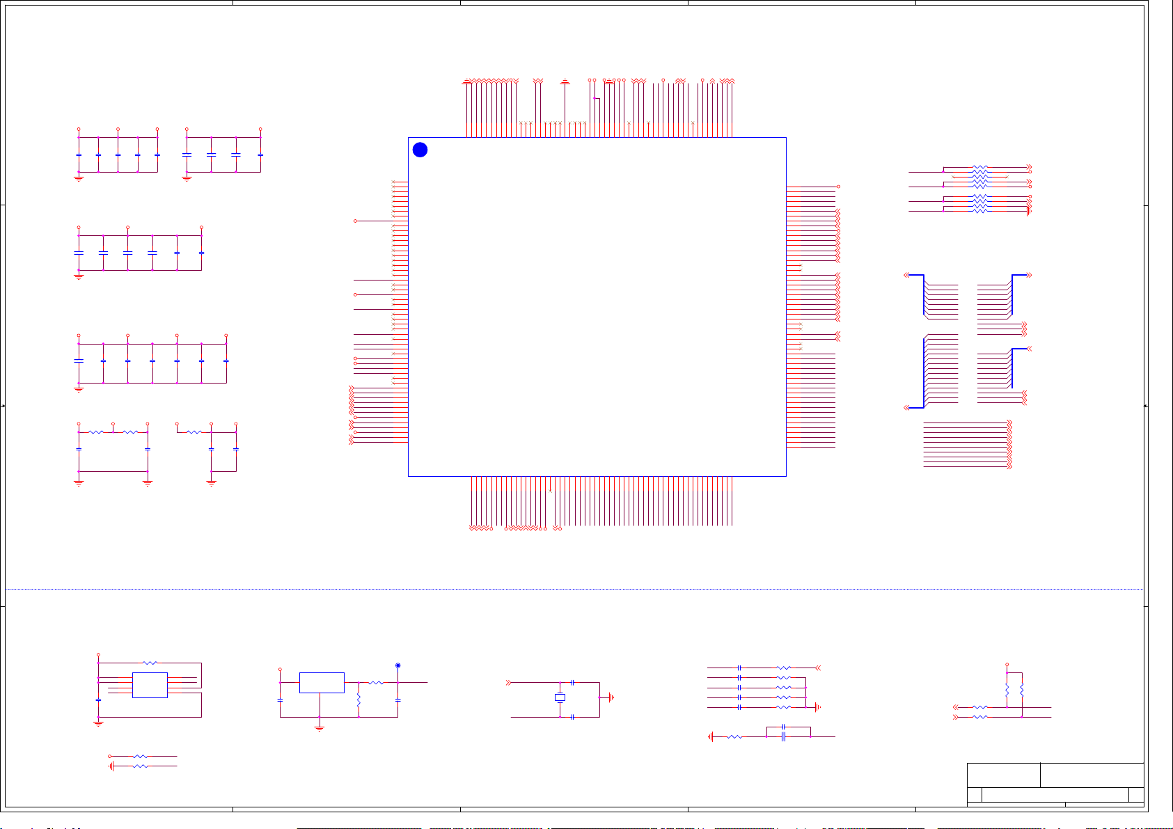
MAINCHIP-MSD3663
11
CV3663LL-A24
A2
412Monday, July 23, 2018
Title
Size Document Number Rev
Date: Sheet of
MAINCHIP-MSD3663
11
CV3663LL-A24
A2
412Monday, July 23, 2018
Title
Size Document Number Rev
Date: Sheet of
MAINCHIP-MSD3663
11
CV3663LL-A24
A2
412Monday, July 23, 2018
RP1 4K7x4
1 2
3 4
5 6
7 8
C15
100nF/16V
R12
4K7
R3 0R
C23
100nF/16V
C11
100nF/16V
U2
FLASH 25Q64
CE# 1
SO 2
WP# 3
VSS 4
SI
5SCK
6HOLD#
7VDD
8
R110 NC
C33 47nF/25V
C22
100nF/16V
C32 47nF/25V R8 150R
C17
100nF/16V
C31 10uF/6.3V
R10 NC/1K
C3
1uF/6.3V
C27 33pF/50V
C13
100nF/16V
RP2 4K7x4
1 2
3 4
5 6
7 8
R5 4K7
C5
10uF/6.3V
C29
100nF/16V
U3
NC/SGM810
GND
1
/RESET 2
VCC
3
C2
1uF/6.3V
MSD3663LS
U1 MSD3663LS
GND 217
RX0N_B
3
RX0P_B
4
RX1N_B
5
RX1P_B
6
RX2N_B
7
RX2P_B
8
AVDD_MOD1
9
RXCN_A
10
RXCP_A
11
RX0N_A
12
RX0P_A
13
RX1N_A
14
RX1P_A
15
RX2N_A
16
RX2P_A
17
HSYNC0
18
BIN0P
19
GIN0P
20
GIN0M
21
RIN0P
22
VSYNC0
23
AVDD3P3_ADC
24
BIN1P
25
GIN1P
26
GIN1M
27
RIN1P
28
CVBS0
34
VCOM
35
CVBS_OUT
36
VDDC6
37
LINEIN_L2
41
LINEIN_R2
42
AUVRM
39
VAG
40
AVDD_AU33
38
LINEOUTL3
45
LINEOUTR3
46
EARPHONE_OUTL
47
EARPHONE_OUTR
48
AVDD33_EAR
49
QP_S
50
QM_S
51
AVDD3P3_DADC
52
IP_S
53
IM_S
54
IFAGC_S
55
IFAGC_T
56
IP_T
57
IM_T
58
AVDD3P3_DMPLL
59
XIN
60
XOUT
61
VDDC7
62
GPIO44
63
GPIO45
64
GPIO46/TX2
65
GPIO48/I2S OUT SD
67
VDDIO_CMD
69
VDDC2
70
AVDD_MOD3
73
PCM_RESET/EJ_RSTZ
74
PCM_IRQA_N
75
PCM_CD_N
76
PCM_REG_N
77
PCM_CE_N
78
PCM_OE_N
79
PCM_WE_N
80
PCM_WAIT_N
81
PCM_IORD_N
82
PCM_IOWR_N
83
PCM_D0
84
PCM_D1
85
PCM_D2
86
PCM_D3
87
VDDC1 169
PWM1 168
PWM0 167
RESET 166
IRIN 165
LVB0- 157
LVB0+ 156
AVDD_MOD4 153
LVB1- 155
LVB1+ 154
LVB2- 152
LVB2+ 151
LVB3- 148
LVB3+ 147
LVB4- 146
LVB4+ 145
LVA0- 144
LVA0+ 143
LVA1- 142
LVA1+ 141
LVA2- 140
LVA2+ 139
LVACLK- 138
LVACLK+ 137
LVA3- 136
LVA3+ 135
LVA4- 134
LVA4+ 133
DP_P0 132
DM_P0 131
DP_P1 130
DM_P1 129
PCM_A0
106
RXCP_B
2RXCN_B
1
RX2P_D 216
RX2N_D 215
RX1P_D 214
RX1N_D 213
RX0P_D 212
RX0N_D 211
RXCP_D 210
RXCN_D 209
VDDC/AVDDL_DVI 208
ARC 207
AVDD_5V 206
HOTPLUG_A 205
HOTPLUG_B 204
HOTPLUG_D 203
CEC 202
GND-EFUSE 197
VDDIO_DRAM 191
VDDIO_DATA1 187
AVDD_MOD 186
DVDD_DDR_DATA 185
SAR1 184
SAR0 183
MHL_DET 180
DDCA_CK 179
DDCA_DA 178
VDDC 177
SPI_DO/SPI-NAND_DO/NANAD_RBZ 176
SPI_CK/SPI-NAND_CK/NAND_ALE 175
SPI-NAND_HOLDN/NAND_WEZ 173
SPI_DI/SPI-NAND_DI/NAND_REZ 172
VSYNC1
29
BIN2P
30
GIN2P
31
GIN2M
32
RIN2P
33
LINEIN_L3
43
LINEIN_R3
44
SPI-NAND_WP/NAND_WP 174
GPIO47/I2S_OUT_WS
66
GPIO49/DISEQC
68
PCM_D4/EJ_TCK
88
PCM_D5/EJ_TDO
89
PCM_D6/EJ_TDI
90
PCM_D7/EJ_TRSTN
91
PCM_A14
92
PCM_A13
93
PCM_A12/EJ_DINT
94
PCM_A11
95
PCM_A10
96
PCM_A9
97
PCM_A8
98
PCM_A7
99
PCM_A6/EJ_TMS
100
PCM_A5
101
PCM_A4
102
PCM_A3
103
PCM_A2
104
PCM_A1
105
TS1_D0 128
TS1_D1 127
TS1_D2 126
TS1_D3 125
TS1_D4 124
TS1_D5 123
TS1_D6 122
TS1_D7 121
TS1_VLD 120
TS1_SYNC 119
TS1_CLK 118
TS0_D0 117
TS0_D1 116
TS0_D2 115
TS0_D3 114
TS0_D4 113
TS0_D5 112
TS0_D6 111
TS0_D7 110
TSO_VLD 109
TS0_SYNC
108 TS0_CLK
107
AVDDL_MOD/VDDC 162
GPIO0/SPDIF_OUT 164
GPIO2/RX2 163
NAND_CLE 171
SPI_CS/SPI-NAND_CS/NAND_CEZ 170
DDCDD_CLK 181
DDCDD_SDA 182
GND2 188
VDDIO_DATA 189
VDDIO_DRAM1 190
AVDD_ETH 192
RN 193
TP 196
TN 195
RP 194
DDCDB_CLK 199
DDCDB_DAT 198
DDCDA_CLK 201
DDCDA_DAT 200
GPIO50/I2S_OUT_BCK
71
LVBCLK- 150
LVBCLK+ 149
PWR_ON/OFF 161
VBL_CTRL 160
GPIO18 159
PANEL_ON/OFF 158
GPIO51/I2S OUT MCK
72
C14
100nF/16V
R13
4K7
C1
10uF/6.3V
C20
100nF/16V
C9
100nF/16V
C6
1uF/6.3V
C134 NC
C135 NC
R15 100R
C10
100nF/16V
C34
NC/100nF/16V
R108 NC
C30 NC
C26
100nF/16V
C25
100nF/16V
R14 100R
C133 NC
C16
1uF/6.3V
R11
NC/47K
C12
100nF/16V
C7
1uF/6.3V
R6 4K7
R7 0R
TPL20
RESET
1
C19
100nF/16V
RD14 100K
C21
100nF/16V
R2 0R
C8
1uF/6.3V
R9 180R
C28 33pF/50V
C4
100nF/16V
C35
NC/1nF/50V
R4 10K
C24
100nF/16V
R109 NC
C18
100nF/16V
X1
24MHz/20PF/10PPM
12
R1 0R
PCM_A14
PCM_A3
PCM_A6
PCM_A1
PCM_A4
PCM_A7
PCM_A2
PCM_A5
PCM_A0
PCM_A10
PCM_A9
PCM_A13
PCM_A12
PCM_A8
PCM_A11
TS0_SYNC
TS0_CLK
TS1_VLD
TS1_SYNC
TS0_VLD
TS1_CLK
TS1_D6
TS1_D5
TS1_D4
TS1_D7
TS1_D1
TS1_D0
TS1_D3
TS1_D2
TS1_D[7:0] TS0_D[7:0]
XTALO
XTALI
PCM_IOWR_N
PCM_OE_N
PCM_IORD_N
PCM_REG_N
PCM_WE_N
PCM_CD_N
PCM_CE_N
PCM_WAIT_N
PCM_IRQA_N
PCM_RESET
PWM0
PCM_A[14:0] PCM_D[7:0]
UART_TX
PWR_ON/OFF
TS0_CLK
TS0_SYNC
UART_RX
TS1_D7
TS1_VLD
TS1_CLK
TS0_VLD
TS1_SYNC
TS0_D6
TS0_D7
TS1_D4
TS1_D5
TS1_D6
TS0_D0
TS0_D1
TS0_D2
TS0_D3
TS0_D4
TS0_D5
PCM_A0
TS1_D1
TS1_D2
TS1_D3
TS1_D0
AUVAG
AUVRM
VBL_CTRL
HDMI0_RX2P
HDMI0_RX2N
CVBSIN
HDMI0_RX0N
HDMI0_RX0P
HDMI0_CLKN
HDMI0_RX1N
HDMI0_RX1P
ARC
HDMI0_CLKP
HDMI_CEC
HDMI0_HPDIN
SPI_DI
SPI_CSN
System-RST
SPI_CLK
SPI_DO
PWM0
AMP-MUTE
TS0_D7
TS0_D6
TS0_D4
TS0_D0
TS0_D1
TS0_D3
TS0_D2
TS0_D5
VCOM0
PANEL_ON/OFF
PCM_A13
PCM_IORD_N
PCM_A14
PCM_A7
PCM_A1
PCM_A9
PCM_A8
PCM_IOWR_N
PCM_OE_N
PCM_REG_N
PCM_A6
PCM_A5
PCM_A4
PCM_A3
PCM_A2
PCM_WE_N
PCM_A10
PCM_IRQA_N
PCM_WAIT_N
PCM_A12
PCM_D2
PCM_CE_N
PCM_A11
PCM_RESET
PCM_CD_N
PCM_D7
PCM_D6
PCM_D5
PCM_D4
PCM_D3
PCM_D0
XTALI
XTALO
PCM_D1
VCOM0
CVBSIN
PCM_D6
PCM_D7
PCM_D3
PCM_D4
PCM_D5
UART_TX
UART_RX
PCM_D1
PCM_D2
PCM_D0
SPI_WP
SPI_DO
SPI_CSN
SPI_DI
SPI_CLK System-RST
PWM1
PWM1
AUVAGAUVRM
AMP-MUTE
PANEL_ON/OFF
VBL_CTRL
PWR_ON/OFF
GIN0M
GIN0M
GIN1M
GIN2M
GIN1M
GIN2M

5
5
4
4
3
3
2
2
1
1
D D
C C
B B
A A
L:PANELOFF
H:PANELON
LVDSPOWER LVDS
VCC-Panel
+3.3V_STB
VCC-Panel
VCC-Panel
+5V_STB
+12V_STB
PANEL-ON/OFF
RXE_C-
RXO_C+
RXO_C-
RXE3+
RXE3-
RXEC+
RXEC-
RXE2+
RXE2-
RXE1-
RXE1+
RXE0-
RXE0+
RXO3-
RXO3+
RXOC-
RXOC+
RXO2-
RXO2+
RXO0-
RXO0+
RXO1-
RXO1+
M-SDA
M-SCL
RXE_C+
Title
Size Document Number Rev
Date: Sheet of
LVDS
11
CV3663LL-A24
A3 512Monday, July 23, 2018
Title
Size Document Number Rev
Date: Sheet of
LVDS
11
CV3663LL-A24
A3 512Monday, July 23, 2018
Title
Size Document Number Rev
Date: Sheet of
LVDS
11
CV3663LL-A24
A3 512Monday, July 23, 2018
R31
NC/10K
R24 22R
TPL30 PANEL-VCC
1
R23 NC/22R
TPL48 RXO1-
1
R138 0R
R27
NC/10K
R20 NC/22R
R137
NC
TPL49 RXO0+
1
Q1 3407
3
1
2
R28 22R
TPL50 RXO0-
1
C45
NC
C48
NC/100nF/16V
TPL67 GND
1
J17 FFC_30PIN
GND2
31
VCC1
3VCC2
2VCC3
1
GND3
24
GND4
17
RXO0-
30 RXO0+
29 RXO1-
28 RXO1+
27 RXO2-
26 RXO2+
25
RXOC-
23 RXOC+
22 RXO3-
21 RXO3+
20
WP
6SCL
5
RXE0-
19 RXE0+
18
RXE1-
16 RXE1+
15
RXE2-
13 RXE2+
12 RXEC-
11 RXEC+
10 RXE3-
9RXE3+
8
GND1
32
SDA
4
GND6
7
GND5
14
TPL35 RXE2+
1
Q3
3904
1
2 3
R22
NC
TPL31 RXE3+
1
TPL36 RXE2-
1
D2 NC/4148
21
C37
100nF/16V
TPL39 RXE0+
1
R139 0R C38
NC
R29 22R
TPL32 RXE3-
1
R140
NC
TPL40 RXE0-
1
J4 FFC_30PIN
GND2
31
VCC1
3VCC2
2VCC3
1
GND3
24
GND4
17
RXO0-
30 RXO0+
29 RXO1-
28 RXO1+
27 RXO2-
26 RXO2+
25
RXOC-
23 RXOC+
22 RXO3-
21 RXO3+
20
WP
6SCL
5
RXE0-
19 RXE0+
18
RXE1-
16 RXE1+
15
RXE2-
13 RXE2+
12 RXEC-
11 RXEC+
10 RXE3-
9RXE3+
8
GND1
32
SDA
4
GND6
7
GND5
14
R30 300K
R21
47K
TPL29 PANEL-VCC
1
TPL41 RXO3+
1
TPL37 RXE1+
1
R17 22R
C36
NC
TPL42 RXO3-
1
TPL45 RXO2+
1
TPL38 RXE1-
1
C44
NC
TPL33 RXEC+
1
TPL43 RXOC+
1
TPL46 RXO2-
1
C46
NC
TPL34 RXEC-
1
C47
NC
TPL44 RXOC-
1
TPL47 RXO1+
1
SDA_PD
SCL_PD
SCL_PD
SDA_PD
RXE1-
RXE1+
RXE0-
RXE0+
RXO2+
RXOC+
RXOC-
RXO3-
RXO3+
RXO0-
RXO0+
RXO1-
RXO1+
RXO2-
WP
RXEC-
RXE2-
RXEC+
RXE2+
RXE3-
RXE3+
WP
RXEC+
RXOC+
RXEC-
RXOC-
RXE3-
RXE3+
RXEC-
RXEC+
RXE2+
RXE2-
RXE1-
RXE1+
RXE0+
RXE0-
LVDS_SEL
LVDS_SEL
5
5
4
4
3
3
2
2
1
1
D D
C C
B B
A A
L:OFF
H:ON
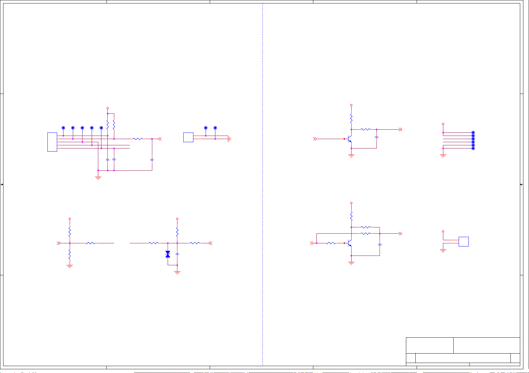
KEY&IR&LED BACKLIGHT
+12V_STB
+3.3V_STB
+12V_STB
+3.3V_STB
+3.3V_STB
+5V_STB
+5V_STB
KEY_IN
IRIN
PB-ON/OFF
PB-ADJUST
VBL-CTRL
BRI_ADJ
LED_R
Title
Size Document Number Rev
Date: Sheet of
KEY&IR&LED
11
CV3663LL-A24
A3 612Monday, July 23, 2018
Title
Size Document Number Rev
Date: Sheet of
KEY&IR&LED
11
CV3663LL-A24
A3 612Monday, July 23, 2018
Title
Size Document Number Rev
Date: Sheet of
KEY&IR&LED
11
CV3663LL-A24
A3 612Monday, July 23, 2018
C42
NC
R41
NC
TPL13
GND
1
TPL68
GND
1
R44 NC
C43
33pF/50V
TPL69
KEY
1
TPL12
IR
1
TPL14
LED
1
TP6
test6-2mm
1
GND
2
GND
3
ADJ
4
ON/OFF
5
+12V
6
+12V
R19
10KJK1
HY-5A
3.3V 1
IR 2
GND 3
LED 4
KEY 5
TPL15
KEY
1
R36 560R
R38
NC/4K7
D1
NC
12
R42 NC
TPL11
3.3V
1
R39
4K7
R35
NC/4K7 R26 1K
R16
4K7 JAGE1
PH-2A_AGE
+12V
1
GND
2
R25 100R
R43 100R
R136 0R Q6
NC/3904
1
2 3
C49
100nF/16V
R40 100R
Q5
3904
1
2 3
C50
NC
J2
NC/PH-2A
11
22
C40
100nF/16V
C41
NC
R18
22R
KEY-1 KEYLED-R
BL-ON/OFF
BL-ADJUST
BL-ADJUST
BL-ON/OFF
3.3V_IR
LED-R
KEY-1
KEY
5
5
4
4
3
3
2
2
1
1
D D
C C
B B
A A
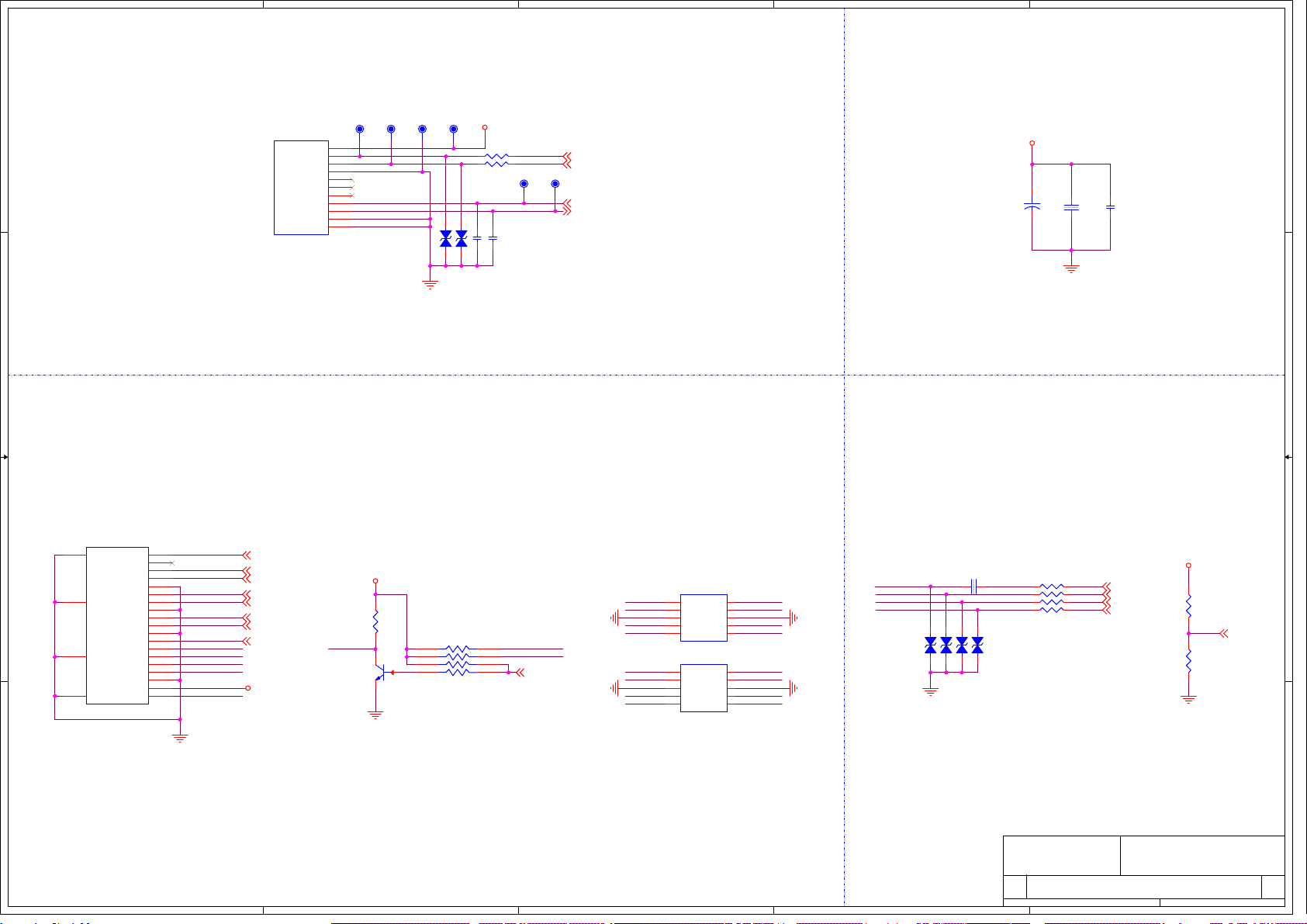
HDMI1 CEC&ARC
USB USBPOWER
OFFLINE
HDMI0/5V
HDMI0/5V
+5V_USB
HDMI0/5V
+5V_USB
HDMI_CEC
HDMI0_RX2P
HDMI0_RX2N
HDMI0_RX1P
HDMI0_RX1N
HDMI0_RX0N
HDMI0_CLKP
HDMI0_RX0P
HDMI0_CLKN
HDMI0_SCL
HDMI0_SDA
HDMI0_ARC
HDMI0_DET
HDMI0_HPDIN
UART-RX
UART-TX
USB0_DM
USB0_DP
Title
Size Document Number Rev
Date: Sheet of
INPUT-USB&HDMI
11
CV3663LL-A24
A3 712Monday, July 23, 2018
Title
Size Document Number Rev
Date: Sheet of
INPUT-USB&HDMI
11
CV3663LL-A24
A3 712Monday, July 23, 2018
Title
Size Document Number Rev
Date: Sheet of
INPUT-USB&HDMI
11
CV3663LL-A24
A3 712Monday, July 23, 2018
C53
100nF/16V
D8
NC
1 2
RP6 10Kx4
1 2
3 4
5 6
7 8
TPL7
TX
1
TPL5
USB-DM
1
Q10
3904
1
2 3
TPL8
RX
1
TPL6
USB-DP
1
D6
NC
1 2
J16 USB3_0-H
VBUS 1
D- 2
D+ 3
GND 4
STDA_SSTX+ 9
STDA_SSRX- 5
STDA_SSRX+ 6
GND_DRAIN 7
STDA_SSTX- 8
SHELL1 10
SHELL2 11
5D1
NC/PESD2510
S1
1S2
2GND
3S3
4S4
5S8 6
S7 7
GND1 8
S6 9
S5 10
R45 0R
5D2
NC/PESD2510
S1
1S2
2GND
3S3
4S4
5S8 6
S7 7
GND1 8
S6 9
S5 10
R135 22R
D5
NC
1 2
TPL9
GND
1
R134 22R
R53
4K7
D10
NC
1 2
D9
NC
1 2
C138
NC
D7
NC
1 2
J7 HDMI
DATA2+ 1
DATA2_SHIELD 2
DATA2- 3
DATA1+ 4
DATA1_SHIELD 5
DAT1A- 6
DATA0+ 7
DATA0_SHIELD 8
DATA0- 9
CLK+ 10
CLK_SHIELD 11
CLK- 12
CEC 13
NC 14
SCL 15
SDA 16
CEC_GND 17
+5V POWER 18
HOT PLUG 19
20
20
21
21
23
23
22
22
C137
NC
R107
1K
R46 0R
TPL4
5V-USB
1
R54 100R CEC
C52
NC
R51 100R ARC
+
C51
220uF/16V
C54 1uF/6.3V
ARC
R57
10K
HDMI0-SCL
HDMI0-SDA
HDMI0-HPD
CEC
HDMI0-SCL
HDMI0-SDA
HDMI0_RX2N
HDMI0_RX1P
HDMI0_RX1N
HDMI0_CLKN
HDMI0_RX2P
HDMI0_RX0P
HDMI0_RX0N
HDMI0_CLKP
HDMI0_RX2N
HDMI0_RX1P
HDMI0_RX2P
HDMI0_RX1N
HDMI0_RX0P
HDMI0_RX0N
HDMI0_CLKN
HDMI0_CLKP
CEC
HDMI-ARC
HDMI-ARC HDMI0-SDA
HDMI0-SCLHDMI0-HPD

5
5
4
4
3
3
2
2
1
1
D D
C C
B B
A A
TUNER-T/T2
+3V3_TUNER
T2_3V3
+3V3_TUNER+5V_USB
T2_3V3
T2_3V3
T2_3V3
+5V_STB
T2_3V3
T2_3V3
XTALO
M-SCL
M-SDA
DIF+
DIF-
ANT_EN IFAGC_T
Title
Size Document Number Rev
Date: Sheet of
INPUT-T/T2TUNER
11
CV3663LL-A24
A3 812Monday, July 23, 2018
Title
Size Document Number Rev
Date: Sheet of
INPUT-T/T2TUNER
11
CV3663LL-A24
A3 812Monday, July 23, 2018
Title
Size Document Number Rev
Date: Sheet of
INPUT-T/T2TUNER
11
CV3663LL-A24
A3 812Monday, July 23, 2018
C105
10uF/6.3V
R94 100R
ANT_POWER
C96 100pF/50V
ON BOARD-T/T2
C102 100nF/16V
ON BOARD-T/T2
R83
4K7
L11 180nH
ON BOARD-T/T2
1 2
U10
SY6280AAC
ANT_POWER
VOUT 1
GND 2
#FLG 3
EN
4
VIN
5
C113 100nF/16V
ON BOARD-T/T2
C115
10uF/6.3V
ANT_POWER
L5 270nH
ON BOARD-T/T2
1 2
R91 0R
TPL54 GND
1
L6 6.8nH
ON BOARD-T/T2
1 2
U7
R842
ON BOARD-T/T2
RF_bias
2
TF1
3
TF2
4
DECT1
5
SCL
6
SDA
7
AVDD
8
AVDD1 18
VOP 17
VON 16
VAGC 15
DVSS
10
CP
9
RFIN
1
AVDD0 24
TFH 23
TFL 22
NC 21
DET2 20
DET3 19
GND
25
DVDD
11
XTAL_I
12
VAGC2 14
XTAL_O 13
C114
1uF/6.3V
ANT_POWER
R111
20K
ANT_POWER
C116
100nF/16V
ANT_POWER
C118
NC
D15
BAV99
ON BOARD-T/T2
1
23
C93 22nF/16V
ON BOARD-T/T2
R89
10K
C120
100nF/16V
ON BOARD-T/T2
GND
GND GND
RF
GND
J10
RF_JACK
ON BOARD-T/T2
RF 1
22
3
344
5
5
C104
100nF/16V
C98
120pF/50V
ON BOARD-T/T2
U9
1117-3.3V
VIN
3
GND
1
VOUT 2
PAD 4
R88 0R
X3 NC
1 2
R86 100R
ON BOARD-T/T2C110
33pF/50V ON BOARD-T/T2
C100
NC
C119
22nF/25V
CT2 1nF/50V
C109
33pF/50V ON BOARD-T/T2
TPL57 AGC
1
C108
NC
TP7 +3V3_TUNER
1
R93 100R
ON BOARD-T/T2
C92 22nF/16V
ON BOARD-T/T2
R92 NC
L12 220nH
ANT_POWER
1 2
L9 270nH
ON BOARD-T/T2
1 2
C99 47nF/25V
ON BOARD-T/T2
L10 FB1K/200mA
ON BOARD-T/T2
C97 100nF/16V
ON BOARD-T/T2
U8
CDT-9NT372-RF01
CAN-T/T2
GND5
1
3.3V
2
SCL
3
SDA
4
GND6
5
NC
6
IF_P
7
IF_M
8
IF_AGC
9
GND1
10
GND2
11
GND4
13
GND3
12
TPL55 IF-D
1
R84 1K8
ON BOARD-T/T2
C101 100nF/16V
ON BOARD-T/T2
C107
NC
TPL51 3.3V
1
TPL52 SCL
1
L8
FB1K/200mA
ON BOARD-T/T2
L7
270nH
ON BOARD-T/T2
12
L4 39nH
ON BOARD-T/T2
12
R87 100R
ON BOARD-T/T2
C106
100nF/16V
RT1 560R
C111 6.8nF/50V
ON BOARD-T/T2
C117
NC
TPL56 IF-M
1
CT1
1.8pF/50V
ON BOARD-T/T2
C112 100nF/16V
ON BOARD-T/T2
C95 120pF/50V
ON BOARD-T/T2
C103 330pF/50V
ON BOARD-T/T2
R114 0R
ON BOARD-T/T2
C94 100nF/16V
ON BOARD-T/T2
R82
4K7
TPL53 SDA
1
5V_Antenna-TU
IF_OUT2_D
M-SCL
M-SDA
IF_OUT1_D
VAGC
VAGC
T_SCL
T_SDA
VOP
VON
IF_OUT2_D
RF_IN
T_SCL
IF_OUT1_D
VON
VOP
T_SDA
IFAGC_T
RF_IN
5
5
4
4
3
3
2
2
1
1
D D
C C
B B
A A
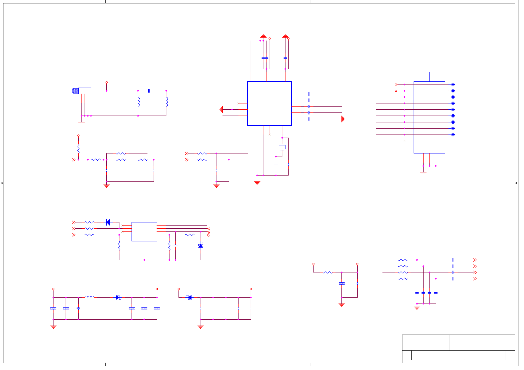
TUNER-S/S2
+3V3_TUNER
+12V_STB
S2_3V3+3V3_TUNER
LNB_POWER
LNB_POWER
LNB_VO
LNB_VO
LNB_POWERLNB_VO
S2_3V3
LNB_POWER
S2_3V3 S2_3V3
LNB_SEL
LNB_EN
DISEQC
LNB-LDROP
IFAGC_S M-SDA
M-SCL
QP_S
QM_S
IP_S
IM_S
Title
Size Document Number Rev
Date: Sheet of
INPUT-S/S2TUNER
11
CV3663LL-A24
A3 912Monday, July 23, 2018
Title
Size Document Number Rev
Date: Sheet of
INPUT-S/S2TUNER
11
CV3663LL-A24
A3 912Monday, July 23, 2018
Title
Size Document Number Rev
Date: Sheet of
INPUT-S/S2TUNER
11
CV3663LL-A24
A3 912Monday, July 23, 2018
C75 100nF/16V
ON BOARD-S/S2
C56
1nF/50V
S/S2
TPL60 AGC
1
L3 6.8uH/1.8A
S/S2
1 2
C76 10pF/50V
ON BOARD-S/S2
R67 51R
ON BOARD-S/S2
R79 22R
S/S2
R63 100R
ON BOARD-S/S2
R72 0R
S/S2
C73 100nF/16V
ON BOARD-S/S2
TPL61 IF-QP
1
C61 100nF/16V
ON BOARD-S/S2
R69 1K
ON BOARD-S/S2
R65 51R
ON BOARD-S/S2
C55
2.2nF/50V
S/S2
C78 10pF/50V
ON BOARD-S/S2
TPL62 IF-IN
1
R71 NC/0R
C86
10uF/16V
S/S2
R68 51R
ON BOARD-S/S2
X2
27MHz/20PF/10PPM
1 2
D14
SS14
S/S2
1 2
L2
5.6nH
ON BOARD-S/S2
12
C132
NC
TPL63 SDA
1
R74 100R
S/S2
TPL65 IF-QN
1
D13 4148
S/S2
2 1
R70
10K
S/S2
J9
RF_JACK_THREAD ON BOARD-S/S2
1
2
3
4
5
C64
33pF/50VON BOARD-S/S2
TPL64 SCL
1
C70 100nF/16V
ON BOARD-S/S2
C67 100nF/16V
ON BOARD-S/S2
RDA5815
QFN20
U4
RDA5815
ON BOARD-S/S2
XOUT
8
VDD 11
XTAL2
9
BBIP 12
GND 20
VCC 16
BBQP 15
BBIN 13
AGC
5
XTAL1
10
PAD 21
VCC 19
GND
7
BBQN 14
LOOP
3
ADD
4
XOUT_EN
6
GND
2
RFIP
1
SDA 17
SCL 18
R75 200K
S/S2
C72 100nF/16V
S/S2
C69 100nF/16V
S/S2
C62 100nF/16V
ON BOARD-S/S2
C60 100pF/50V
ON BOARD-S/S2
R80
100K
S/S2
C68 100nF/16V
ON BOARD-S/S2
C71 100nF/16V
S/S2
C82
33pF/50V ON BOARD-S/S2
TPL66 IF-IP
1
C74 100nF/16V
S/S2
R115 0R
ON BOARD-S/S2
C57
1nF/50V
S/S2
D11 SS14
S/S2
1 2
C79 10pF/50V
ON BOARD-S/S2
R64 100R
ON BOARD-S/S2
R112 100R
S/S2
C89
10uF/25V
S/S2
D12 SS14
S/S2
12
C84
10uF/6.3V
S/S2
C66 2.7pF/50V
ON BOARD-S/S2
R66 51R
ON BOARD-S/S2
C58
NC
C87
10uF/16V
S/S2
R113
100K
S/S2
L1
5.6nH ON BOARD-S/S2
12
C88
100nF/16V
S/S2
C81
33pF/50V ON BOARD-S/S2
C83
22nF/50V
TPL58 LNB POWER
1
C59
NC
C85
100nF/16V
S/S2
C77 10pF/50V
ON BOARD-S/S2
C80
1nF/50V
ON BOARD-S/S2
R122 0R
CAN-S/S2
U6 JW4005
S/S2
SW 1
VO 2
ISET
5
13/18V 7
FAULT
4
EN/EXTM
6
LDROP
8LNB 3
9
GND C91
1uF/25V
S/S2
C65 2.2pF/50V
ON BOARD-S/S2
C63
33pF/50V
ON BOARD-S/S2
TPL59 3.3V
1
C90
10uF/25V
S/S2
U5
CDT-9NS161-RD41
CAN-S/S2
LNB
1
VCC
2
AGC
3
IP
4
IN
5
QN
6
QP
7
SDA
8
SCL
9
GND
11
GND
12
GND
14
GND
13
XOUT
10
SW
SW
SCL_RF
SDA_RF
IF_QP
IF_QN
IF_IP
BBQN
BBQP
BBIN
IF_IN
BBIP
M-SDA
M-SCL
IF_QP
IF_IP
IF_QN
IF_IN
IFAGC_S1
IFAGC-S
IFAGC-S
BBQP
BBQN
BBIN
BBIP
SDA_RF
SCL_RFIFAGC_S1
This manual suits for next models
1
Table of contents
Other Shivaki LED TV manuals

Shivaki
Shivaki STV-32LED14 User manual

Shivaki
Shivaki STV-32LED5 User manual

Shivaki
Shivaki SZTV-40LED6T2 User manual

Shivaki
Shivaki STV-16LED1 User manual

Shivaki
Shivaki STV-16LED1 User manual

Shivaki
Shivaki STV-32LED11A User manual

Shivaki
Shivaki STV-42LED11A User manual

Shivaki
Shivaki STV-22LED14E User manual


