Shivaki STV-16LED1 User manual

LED TV
SERVICE MANUAL
Editor
Verify
Approver
STV-16LED1

General description ----------------------------------------------------3
Contents
Features ---------------------------------------------3
Function layout ---------------------------------------------5
PCB dimension ---------------------------------------------6
Schematic of IR and Keyboard -----------------------------------7
Main board Power supply -----------------------------------7
Interface definition -----------------------------------8
Software Update Steps -----------------------------------11
Power ----------------------------------12
IR +KEY Board ----------------------------------18
Bom list -----------------------------------19
Board service manual -----------------------------------21
Schematic -----------------------------------28
1. General description
LM1EC is a multi-purpose and energy-efficient LCDTV control board with
single/dual 8bit/10bit LVDS interface, the resolution of LCDTV panel is up to 1920*1080.
It also can support LED backlight LCD panel.
LM1EC supports PAL/SECAM/NTSC、HDMI、Component、、PC-RGB AV、S-Video
video and audio input as well as SCART input and output , an audio amplifier which
supports 2x2W (8ohm) outputs and an earphone&SPDIF output are all built in .
Software upgrade and multimedia playback function are applicable with the USB
slot.
LM1EC supports H.264 video decode.
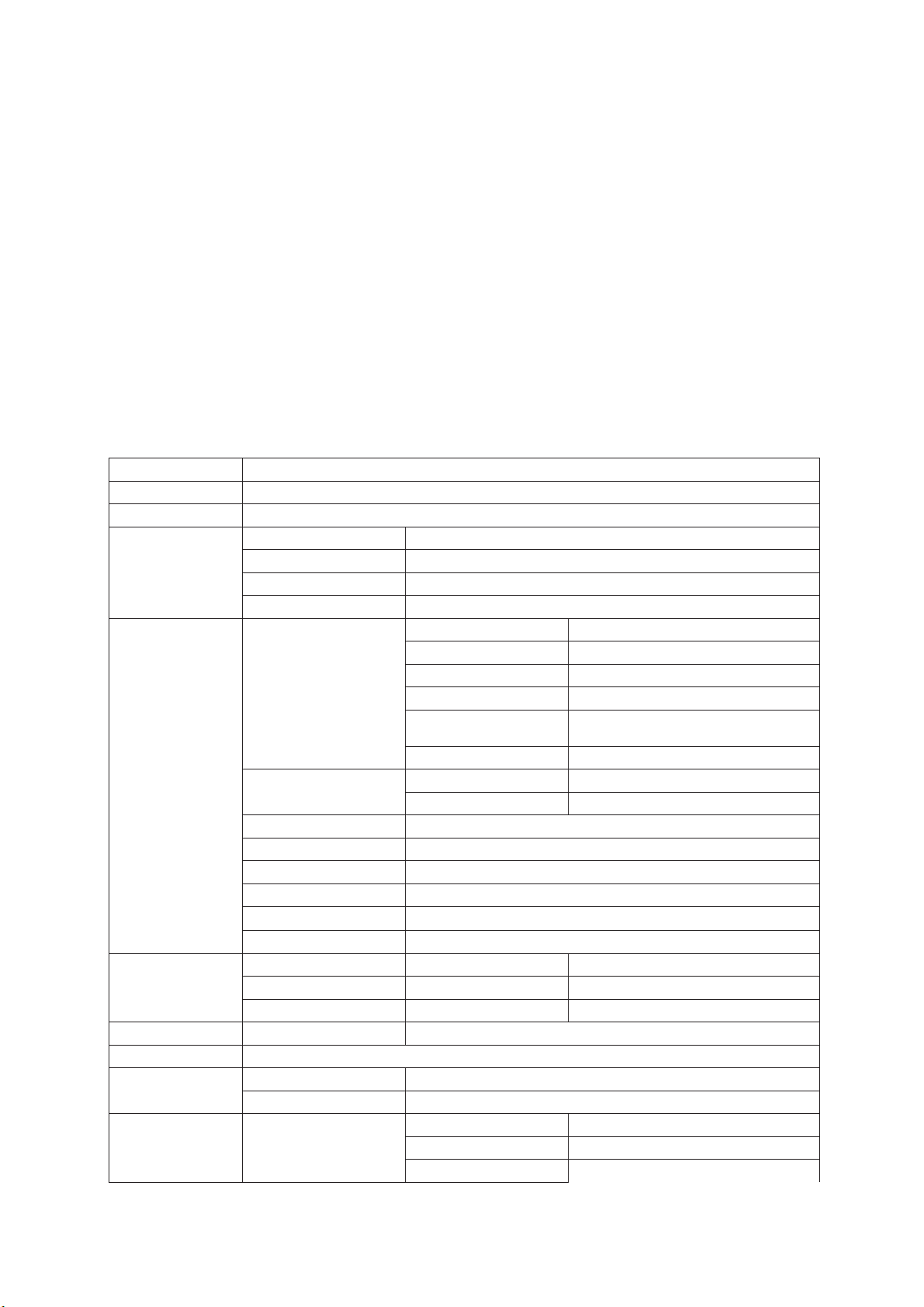
2. Features
Chipset MST6M48RVS
Market Area Asia Pacific
OSD Language English/Russian
Type TFT-LCD, LED backlight LCD
Resolution up to 1920*1080
Interface single/dual 8bit/10bit LVDS
LCD Panel
Panel power 3.3V,5V,12V optional
Receiving Range 43.25MHz~863.25MHz
Input Impedance 75 ohm
Video System PAL,SECAM,NTSC
Sound System BG,DK,M,N,L/L’
Max Storage
channels 200
ATV
VBI CC/V-CHIP/Teletext 100pages
Video System PAL/NTSC/SECAM
AV Video Level 1.0 Vp-p +- 5%
S-Video S-Y:0.714Vp-p +- 5% S-C:0.286Vp-p +- 5%
Component 480i,480p,576i,576p,720p,1080i,1080p
SCART Full SCART with RGB&CVBS input/output
HDMI 480i,480p,576i,576p,720p,1080i,1080p
PC-RGB up to 1920*1080@60Hz
Video Input
USB2.0 Multimedia playback and software upgrade
PC-RGB Earphone Input 0.2 -2.0 Vrms
AV&S-Video L/R RCA Input 0.2 -2.0 Vrms
Audio Input
Component L/R RCA Input 0.2 -2.0 Vrms
Audio Output Max Output Power 2*3W
Key Function POWER,INPUT,MENU,CH+,CH-,VOL+,VOL-
Input DC12V
Power Power Management Standby Power Consumption <0.1W(board only)
TV 1IECtype,75
AV 1 RCA Terminal(yellow)
Terminal Input
S-Video 1 S-Video Terminal

AV&S-Video Audio 2 RCA Terminal(red,white)
PC-RGB 1 D-Sub Terminal(15PIN)
PC-RGB Audio 1 Earphone Terminal ( black )
Component 3 RCA Terminal (green,blue,red)
Component Audio 2 RCA Terminal(red,white)
HDMI 1 HDMI Terminal
USB 1 USB Terminal
Output Earphone Output 1 Earphone Terminal(black)
Expandable
Function DVD Combo
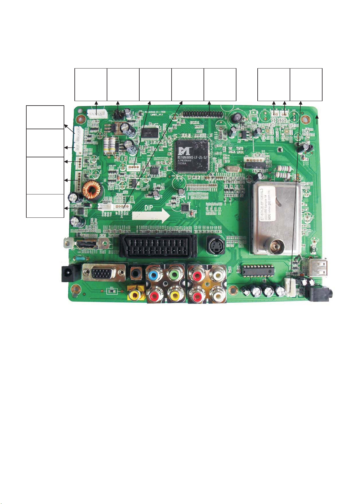
3. Function layout
XS803
Speaker
Output
XS444
LVDS
Output
J501
Panel
Power
Select
CN001/
CN002
LED
Backlight
XS502
Inverter
Interface
XS606
Software
Upgrade
XS607
IIC
Interface
XS901
External
USB
XS601
IR&LED
Interface
XS610
Key
Interface
XS501/
XS504
Mainboard
Power
supply
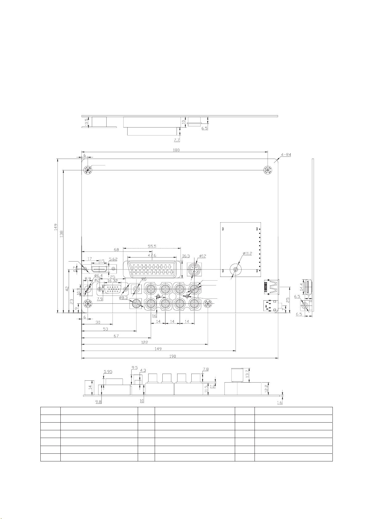
4. PCB dimension
PCB Height =20.5mm
PCB Length = 190mm
PCB Width = 149mm
PCBScrewBoreSize:Diameter is 3.5mm
2- 4Φ
2- 2.4φ
8- 8.3φ
8- 10.8φ
4- 4.4φ
2- 3Φ
18
17
16
123
45 678910
11 12 13 14 15
No Description No Description No Description
1 HDMI In 7 Component-Pb In 13 AV In
2 FULL Scart 8 Component-Y In 14 AV&S-Video R in
3 S-Video In 9 Component-R In 15 AV&S-Video L in
4 DC 12V In 10 Component-L In 16 Earphone Out
5 PC-RGB In 11 SPDIF Out 17 USB2.0 In
6 PC-RGB Audio In 12 Component-Pr In 18 RF In

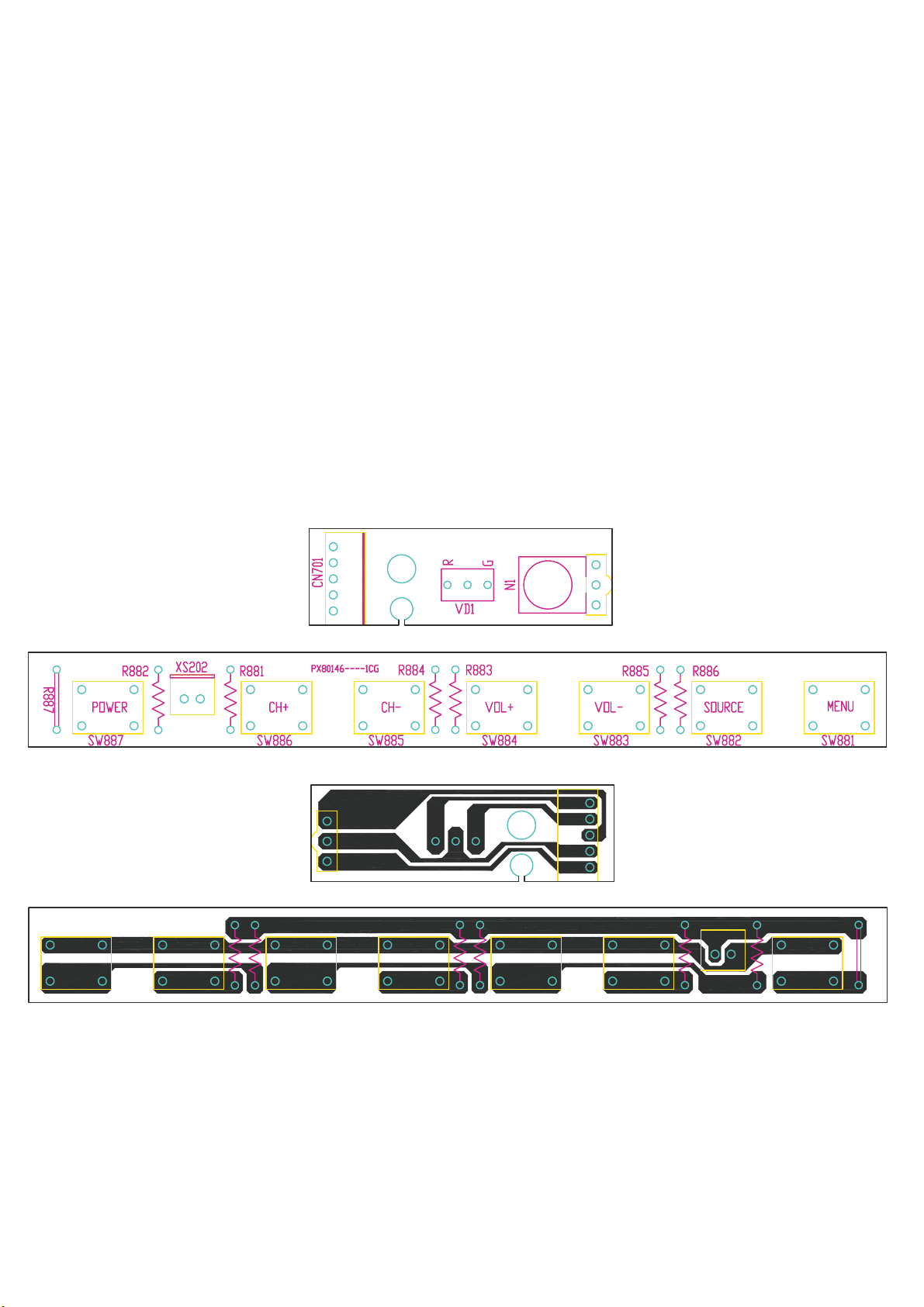
5. Schematic of IR and Keyboard
6. Main board Power supply
The power supply for this board is DC12V, the maximum current is 4A.
7. Interface definition
‹XS501(7PIN/2.0)Main Board Power Supply
PIN No. Definition Description
1 12V
2 12V +12V DC Power Supply
3GND
4 GND Ground
5 STB Standby Control
6 5VSB
7 5VSB +5V Standby Power supply
‹XS504(4PIN/2.0)Main Board Power Supply
PIN No. Definition Description
1GND
2 GND Ground
35V
45V +5V DC Power Supply
‹XS601(5PIN/2.0)IR and LED board Interface
PIN No. Definition Description
1 GND Ground
2IR IR
3 LED-GREEN Green Indicator
4 LED-RED Red Indicator
5 5V +5V DC Power Supply
‹XS610(3PIN /2.00):Key Interface
PIN No. Definition Description
1GND GND
2Key1
3 Key0
‹XS502 (6PIN/2.0)Inverter
PIN No. Definition Description
1 GND Ground
2 GND Ground
3 DIMMING Brightness Adjustment for panel
4 BL_OFF Backlight On/Off Control for Panel
5 BL_12V
6 BL_12V +12V DC power Supply
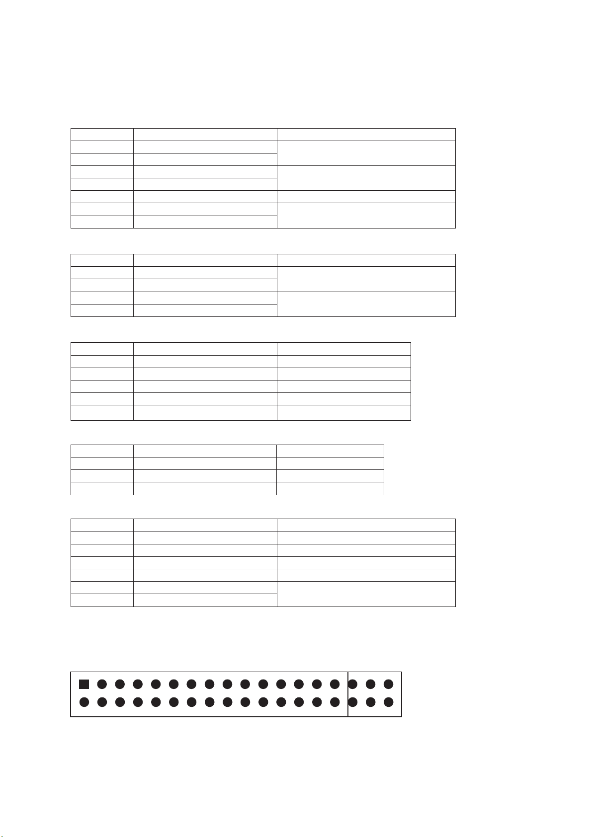
‹XS444 ()30PIN/2.0()LVDS Output
30
29
2
135
36

PIN No. Definition Description PIN No. Definition Description
1 VCC Panel Power 19 RXE0+
2 VCC Panel Power 20 RXE0-
3 GND 21 RXE1+
4 VCC Panel Power 22 RXE1-
5 GND 23 RXE2+
6 GND 24 RXE2-
7 RXO0+ 25 GND
8 RXO0- 26 GND
9 RXO1+ 27 RXEC+
10 RXO1- 28 RXEC-
11 RXO2+ 29 RXE3+
12 RXO2- 30 RXE3-
13 GND 31 RXO4+
14 GND 32 RXO4-
15 RXOC+ 33 RXE4+
16 RXOC- 34 RXE4-
17 RXO3+ 35 GND
18 RXO3- 36 GND
Note: You can select ODD if you use single LVDS input.
JP501(2X3PIN/2.5): Panel Power Select
PIN No. Definition Description
1 +12V
3+5V
5 +3.3V
24、、6VCC_PANEL Panel Power Supply
Note: Please select the appropriate power by jumper for panel.
XS606(4PIN/2.0):Software upgrade Interface
PIN No. Definition Description
1 5VSB +5V
2 GND Ground
3RXD RX
4TXD TX
XS803()4PIN/2.54()Speaker Output
PIN No. Definition Description
1 RO Audio Right Channel Output
2 GND Ground
3 GND Ground
4 LO Audio Left Channel Output
51
‹XS607(4PIN/2.0):IIC Interface
PIN No. Definition Description
1 WP Write Protect
2 GND Ground
3 3V3 +3.3V DC Power Supply
4 SDA SDA of IIC
5 SCL SCL of IIC
‹XS901(4PIN/2.0)External USB Interface
PIN No. Definition Description
1U5V
2D-
3D+
4GND
‹CN001/CN002(2PIN/2.0)LED Backlight Interface
PIN No. Definition Description
1H
2L

8. software Update Steps:
Step1: Copy merge_6M48.bin file to USB disk, and then plug the disk to USB slot.
Step2: Power on the LCDTV.
Step3: Press MENU key,then left or right key, call the main menu as below:
OSD Language English
TTX Language
Blue Screen
OSD Duration
User Reset
Software Update USB ()
OPTION
Step4: Use up or down key, move the highlight bar to Software Update(USB) and press OK
key.
Step5: Press left key to confirm to software update or right key to cancel the operate.
Step6: Wait the end of this operation and then the LCDTV will be restart automatically.
10 IR KEY Board Part+
9 External power(AC/DC ADAPTER)
The power output is DC12V,the maximum current is 3A
STV BOMSTV 16LED116LED1BOM
1BLM1EC--01A-ZG 1MST6M48 mina board
2BXATB254 B- -----# 1 Tuner
31 PCS
5
7
8
PX80146----1CG
10
PCS
11 BPD0063----DT 1PCS AC ADAPTER
1PCS
13
BT 0534B CV- --- #
PCS
Remote
14 MT1X0004 T3G--- 2PCS BATTERY R03P 7 Um4(# )
15
2
16
PCS Power line
17
JW4201-C004-AG
18
19
20
1PCS
21
1PCS
22
Carton
23
PCS
24
PCS
25
PCS
26
PCS
27
PCS
28
PCS
29
PCS
30
PCS
31
PCS
32
PCS
33
PCS
34
PCS
35
MJ0X0319B--JC
36
SCC-306R0FD-HG
SCREW M3*6
11 BOM LIST
4
PCS
PCS
LED Red green(/ )
DLD3B002 N8G---
NBRM H8638AN G-- 1IRPCS
PCS
7
6
KTA11VA003 5G-- PUSH SWITCH 5mm()
RZ 000 2NBNNQG-- 1PCS 7 5mm connection.
1PCS +IR KEY board
Key line
9
1PCS
IR line
1
12
Speaker
Pannel line
Speaker line
1PCS
1
GAWH2001 AG---- KEY board socket
PVC
MK0X0413A--KR
MA0X0843---A3
1
1
Back AV label
1
1Terminal label
Pack bag foe CBU (550*500)
Pack bag foe manual (240*290)
MG3X0128---E3G
1
1
1
1
1
MG5X0010---KR
MJ0X0319A--JC
MJ0X0319D--JC 1
1
MJ1X0007---L1G
4
PCS
37
4
PCS
38
39
SCREW M3*8I
4PCS
SDAC308R0FF-HG
JW2151-V002-AG
JB5351-V001-AG
ESB4R0T010—
JSK301-S001-4G
MA0X0836A- A3-
MA0X0838A--A3
MG0X0102A--GLG
MG0X0113---GQ#
1
MJ0X0319C--JC
SCREW M4*10
3PCS
SCAC40010FD-HG
AAA
JP3122-C00124#
MA0X0836B- A3-1PCS Side label
MA3X0162G--AS 1PCS POS tie
MF1X0462A--F1
1PCS
User manual
MF2X0055B--F1 PCS
1
Warranty bill
MA3X0093---A7 2PCS Paper gasket
MB5X0012---E3G 2PCS Metal belt (55mm)
Wire clamp
Carton handle
Packing bubble (Left up)
Packing bubble (Right up)
Packing bubble (Left down)
Packing bubble (Right down)
Pad(10*10*2)
40
1
41
2
PCS
42
44
46
43
21
PCS
PCS
2
45
SKA-308R0FF-HG SCREW ST3*8
SCREW SJ2822-3*8
SLC-308R0FF-HG
SQA-306R0FF-HG SCREW SJ2824-3*6F
5
PCS
SQA-308R0FD-HG
47
48
49
50
SSAA30012FE-HG SCREW 3*12
SCREW ST3*8F
PCS
PCS
PCS
PCS
PCS
PCS
1
1
1
1
1
RDB222J NAATUG-16W 22K/.
RDB122J NAATUG-16W12K/.
RDB332J NAATUG-16W33K/.
RDB561J NAATUG-1 6W 560/
RDB562J NAATUG-16W56K/.
RDB822J NAATUG-16W82K/.
PCS
1

12. Board service manual
6M48
HDMI L/R PC-RGB
SCART1
External
YPbPr External DVD Tuner
15330 15330
LVDS Out
A-Type
AMP 1517
DDR
FLASH
Speaker
USB RGB AV/L/R OutAV/L/R In AV L/R S-Video
Signal flow chart
Earphone Out

Power
N401
6M48
AVDD1P2
DVDD_DDR_1_2V
VDD33
ADC2P5
+ 2_5V _PGA
+ 1_8V _DDR2
2.5V
AVDD_EAR33
AVDD _DMPLL
12V
Adapter
F501
Fuse
Inverter
V007
MOS
N802
AMP
N506
DCDC
1539
N501
MOS
N502
1117-3.3V
L505
FB
Jupmer V506
MOS LVDS Power
+12VSTB
+5VSTB 5V3.3V
N507
DCDC
1539/1530
L503
FB
N505
1084-ADJ
L508
FB
L509
FB
R523
4.7R
R527
4.7R
N504
1084-ADJ
L507
FB
N201
DDR
1.8V
V592
MOS USB1
5V_USB1
F592
FUSE USB2
5V_USB2
N503
1084-3.3
L504
FB
L510
FB
3.3VSTB
N602
FLASH
N300 15330
N302 15330 Ect.
N202
MOS R720 150 R
R721 150R
Tuner
L002
10uH
N003 2481
N004 2481
LED Backlight
LED Backlight
12V
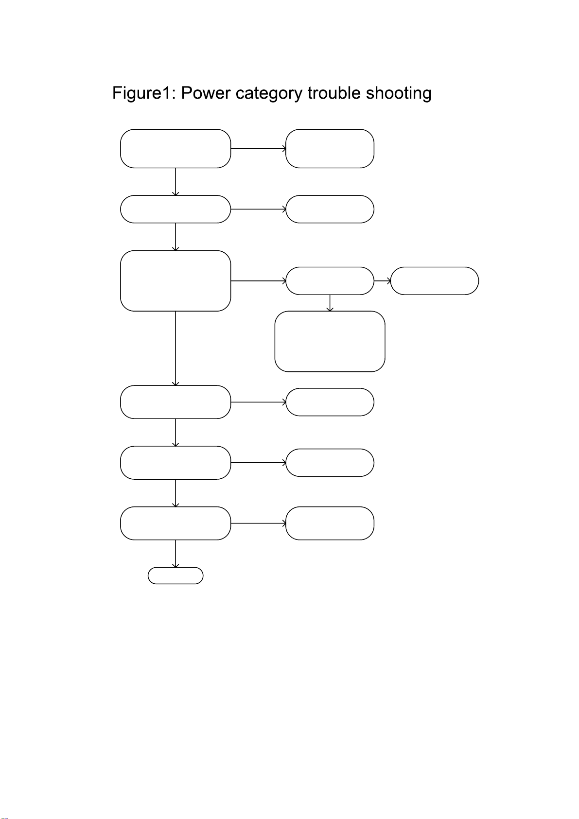
After connect external
adapter, +12VSTB
( Pin1 of N506) is OK?
NCheck Fuse and
+12VSTB network
If +5VSTB (Pin5/6 of
N506) is OK? Check perpheral
circuit of N506
If these output points
are OK: N502-3.3V,
N507-1.2V, N505-
2.5V,N504-1.8V,V592-
5V,F592-5V
Check N501
perpheral circuit
If 3.3VSTB (output of
N503) is OK? Check perpheral
circuit of N503
If 12V (output of N202)
is OK? Check perpheral
circuit of N202
If outputs of N003 and
N004 are OK?
OK
Check perpheral
circuit of
N003&N004
If 5V(output of
N501) is OK?
N502/N507/N505/N504
/V592/F592 is
damaged or output
network is short circuit
N
NN
N
N
N
Y
Y
Y
Y
Y
Y

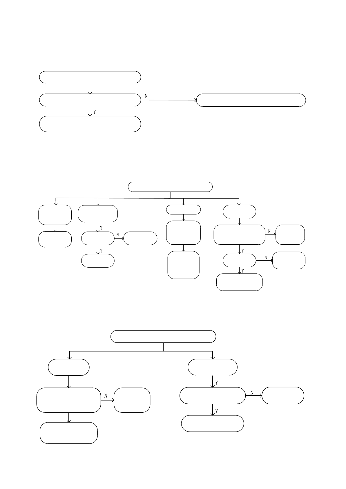
Backlight is on but screen is black or video is unnormal
Figure2: Display part
If LVDS cable is connected OK?
Check LVDS output circuit
If LCD panel is OK?
If panel power supply is OK?
Change or re-plug in LVDS cable
Check LVDS output circuit
Change LCD panel
Check panel power supply part
Check source select and source
Y
Y
Y
Y
N
N
N
N
Screen is black
Figure3: Display part
If pin3 of XS502 is normal?
H:Normal L:Standby
If inverter power supply is OK?
If LCD panel is OK?
If panel power supply is OK?
Check inverter control circuit
Check inverter power supply circuit
Change LCD panel
Check panel power supply part
Check Inverter or inverter cable
Y
Y
Y
Y
N
N
N
N

No audio
Figure4: Audio part (No audio)
If audio signal input is normal?
If AMP power supply is OK?
(PIN7 of N802)
If volume and MUTE setup is OK?
If XS805 has audio output?
Check external audio input
Check AMP power supply circuit or SMPS
Adjust volume and MUTE
Check external speaker
If Pin4/6 of N802 have outputs?
Y
Y
Y
Y
N
N
N
N
Check earphone
Check 6M48 audio input and output
circuit
Y
N
Check Perpheral Circuit of N802
TV doesn’t search/ no picture
Figure5: Function part (TV video trouble shooting)
If external RF signal input is normal?
If Tuner power supply is OK?
(Pin7 of A701,5V)
If VT power supply of tuner is OK?
(Pin9 of A701,33V)
If IIC data is OK?(Pin4,5 of A701)
Check external RF equipment
Check Tuner power supply circuit
Check 33V oscillation circuit
Check IIC network
If SIF output is OK?(Pin11 of A701)
Y
Y
Y
Y
N
N
N
N
Change tuner
Check V701/Z701 circuit
Y
N
TV hasn’t so und, but pic ture is OK
Figure6: Function part (TV hasn’t sound)
If ot her source has s ound
Check Z702 circuit
Refer to “no sound ”mainte nance proc ess
TV has n’t sound , but pic ture is OK
Figure7: Function part (PC)
Pict ure is not
at the c entre
of sc reen
Perform “auto
adjust ”
Miss color pure
color c ast
If R GB input
signal i s OK ?
Check RGB
input c ircuit
Check PC-
RGB s ource
Picture jitter
If VS&HS
signal i s
normal ?
If VS&HS
signal i s OK ?
Perform
“auto adjus t ”
or mode not
supported
No si gnal
display ed
If pin1 of N300 is OK?
H:SCART RGB
L:PC-RGB
Check pin1
of N300
network
Chec k pin 4/7/9/12
of N300 network
Chec k
VS&HS i nput
Circuit
Figure8: Function part (External YPbPr /DVD)
YPbPr/DVD
No s ignal
display ed
Miss colorpure
color c ast
If pin1 of N302 is OK?
H:YPbPr
L:DVD
Chec k pin 1
of N 302
netw ork
Check pin 4/7/9/12
of N302 netw ork
If YPbPr/DVD input
signal is OK ?
Chec k Y PbPr/DVD
input circuit
Chec k YPbPr
source
Other manuals for STV-16LED1
1
Table of contents
Other Shivaki LED TV manuals

Shivaki
Shivaki STV-32LED5 User manual

Shivaki
Shivaki SZTV-24LED4 User manual

Shivaki
Shivaki STV-16LED1 User manual

Shivaki
Shivaki STV-32LED11A User manual

Shivaki
Shivaki STV-42LED11A User manual

Shivaki
Shivaki SZTV-40LED6T2 User manual

Shivaki
Shivaki STV-32LED14 User manual

Shivaki
Shivaki STV-22LED14E User manual


