Shockwave Aquatic AV AD600.5 Operating manual
USER / INSTALLATION MANUAL
PLEASE READ THIS INSTRUCTION MANUAL BEFORE
INSTALLATION AND OPERATION
AD600.5
COMPACT 5/4/3 CHANNEL
WATERPROOF AMPLIFIER

1 Getting Started...........................................................................................................
1.1 Contents..............................................................................................................
1.2 Key Features.........................................................................................................
2 Installation.................................................................................................................
2.1 Installation Precautions........................................................................................
2.2 Mounting Precautions..........................................................................................
2.3 Wiring Precautions...............................................................................................
3 Connections and Controls..........................................................................................
3.1 Power & Speaker Connections..............................................................................
3.2 Input Connections & Controls..............................................................................
4 Input Wiring..............................................................................................................
4.1 Low-Level (RCA) Input Wiring..............................................................................
4.2 High-Level (Speaker) Input Wiring........................................................................
5 Output Wiring............................................................................................................
5.1 5 Channel Mode...................................................................................................
5.2 Bridged 5 Channel Mode......................................................................................
5.3 4 Channel Mode...................................................................................................
5.4 Bridged 4 Channel Mode......................................................................................
5.5 3 Channel Mode...................................................................................................
5.6 Bridged Mode.......................................................................................................
6 Amplifier Operation...................................................................................................
6.1 Setting Operating Level........................................................................................
6.2 Setting Bass Boost...............................................................................................
6.3 Setting Crossovers................................................................................................
6.4 Final System Checks.............................................................................................
7 Troubleshooting.........................................................................................................
8 Specifications & Dimensions......................................................................................
8.1 Specifications.......................................................................................................
8.2Dimensions...........................................................................................................
9 Warranty Information.................................................................................................
3
3
3
4
4
4
5
6
6
6
7
7
8
9
9
9
10
10
11
11
12
12
12
12
13
14
15
15
15
16
Table of Contents AD600.5 COMPACT 5/4/3 CHANNEL AMPLIFIER
2www.aquaticav.com

When first unpacking your new amplifier please check first that the package contains all of the
items below. If something is missing, contact the store where you purchased the product.
• Waterproof Amplifier
• Four (4) Stainless Steel Self Tapping Mounting Screws
• User/Installation Manual
1.1 Contents
• Class-D Digital Amplifier
• 600 Watts of Maximum Power Output
• 50 Watts x4 + 200 Watts x1 Continuous @ 4-Ohms
• 75 Watts x4 + 300 Watts x1 Continuous @ 2-Ohms
• 150 Watts × 2 Continuous @ 4-Ohms Bridged
• 2-Ohm Stable
• Low Level RCA Inputs
• High Level Speaker Inputs
• Bass Boost Adjustment (0 to +18dB)
• Low Distortion MOS-FET Power Supply
• 12dB/Oct. Low/High Pass Electronic Crossover
• Signal-to-Noise Ratio: ≥70dB
• Variable Gain Controls
• Turn-On/Off Muting Circuitry (Soft Mute)
• Ground Loop Isolation Input Circuit
• Power and Protection LED
• Corrosion Resistant Nickel Plated Connections
• 4 Layer Conformal Coated PCB Assembly
• Waterproof IP65
• Hardwired Input / Output and Speaker Cables
• Low Profile, Compact Footprint
1.2 Key Features
Getting Started AD600.5 COMPACT 5/4/3 CHANNEL AMPLIFIER
3www.aquaticav.com

Choose a mounting location in that provides adequate ventilation around the amplifier. If
possible, mount the amplifier so ventilation air runs along the length of the fins rather than across
them.
2.2 Mounting Precautions
2.1 Installation Precautions
If you do not have the necessary skills do not install the amplifier yourself. See your local
authorized Aquatic AV dealer for installation recommendations.
This amplifier is for applications with a negative ground, 12V power supply.
Mounting the amplifier in a tight space without any air movement will damage the unit’s internal circuitry over time.
Mount the amplifier on a rigid surface away from subwoofer enclosures or any area that is prone
to vibration. Do not install amplifier on plastic or on any other combustible material.
Check clearances on all sides of the planned installation before drilling any holes or installing any
screws.
Take special care when you work near the gas tank, fuel lines, hydraulic lines and electrical
wiring.
Never operate the amplifier when it is unmounted. Attach all audio system components securely
within the amplifier to prevent damage, especially in an accident.
Do not mount this amplifier so that wire connections are unprotected, in a pinched condition, in
contact with any metal surfaces in your vessel, or likely to be damaged by nearby objects.
Before making or breaking power connections in your system, disconnect the marine vessel
battery. confirm that your head unit or other equipment is turned off while connecting the input
jacks and speaker terminals.
Mount the amplifier so that the panel controls are easily accessible after installation.
If you need to replace the power fuse, replace it only with a fuse identical to that supplied with
the amplifier. Using a fuse of a different type or rating may result in damage to your audio system
or your amplifier which is not covered by the manufacturer’s warranty.
Installation AD600.5 COMPACT 5/4/3 CHANNEL AMPLIFIER
4www.aquaticav.com

Read all wiring precautions before starting any installation. If you are not sure of the connections,
please contact your local authorized Aquatic AV dealer.
Before you start, make sure the source unit’s power is switched off.
Disconnect the negative battery terminal before doing any electrical work. Always disconnect the
negative (–) battery post first, followed by the positive (+), and when it’s time to go back together,
connect the positive (+) post first, followed by the negative (–). This can minimize the chance
of sparks and voltage spikes, and is a good general practice when dealing with any DC electrical
system.
Bad grounds under are the number one cause of problem installs.
Always use the shortest length of ground wire possible between chassis ground and the amplifier.
Never use a ground wire longer than the one we provide.
A good chassis ground connection is critical to minimize resistance and avoid noise problems.
Clean off any paint prior to making connections. Securely connect the ground wire to the chassis
and the source unit ground.
The ground wire and power wire are equally important; if either one of them is compromised, the
amplifier’s performance will degrade or cease to function.
Always route wires and cables safely, avoiding sharp edges and burrs along the way. Use wire loom
when possible. Check for proper length to both termination points, knowing where each compo-
nent mounts, before you cut anything.
When routing RCA cables, always keep these cables away from the power cables and output
speaker wiring.
Using cables that are too long can cause signal loss and act as an antenna for noise. Use only
high quality RCA cables that are no longer than necessary to make connections between the
source unit and amplifier.
Make sure each connection is clean and secure and insulate final connections with electrical tape
or shrink tubing.
2.3 Wiring Precautions
Improper connections may damage equipment.
Always install a master fuse within 12” of the battery for any additional equipment added to your
installations electrical system. The mini-fuse installed on the main amplifier only protects the
internal circuitry, not the wiring. In the event of a short, failure to install a fuse near the battery
can cause damage to your electrical system or the possibility of fire.
The way speaker wires are marked for polarity (+/–) varies from brand to brand. Some manufactur-
ers use the stripe as positive (+), while others use the stripe as negative (–). Be sure to check the
documentation of each component you’re dealing with before making connections.
Do not open the amplifier. There are no user-serviceable parts inside. If you require assistance,
consult your local authorized Aquatic AV dealer.
Installation AD600.5 COMPACT 5/4/3 CHANNEL AMPLIFIER
5www.aquaticav.com

3.1 Power & Speaker Connections
POWER
INPUT
SPEAKER
OUTPUT
Power Input
Power Connector:
Battery (+12V)
Ground (-)
Battery (+12V)
Ground (-)
2x 40A Fuse
Speaker Output
Speaker Connector:
Front Left (CH1)
Front Right (CH2)
Rear Left (CH3)
Rear Right (CH4)
Subwoofer (CH5)
Amplifier Turn On
3.2 Input Connections & Controls
HI
INPUT
LOW
INPUT BASS
SUB
LEVEL
LOW
PASS EQ
PWR
PRT
LEVEL LEVEL
HIGH PASS HIGH PASS
-REAR-
-FRONT-
MIN MAX MIN MAX
50 250 50 250
MIN MAX 50 250 018dB
White (+)
Front Line Input (Black)
Rear Line Input (Gray)
Subwoofer Line Input (Purple)
CH1 - Front Left (White)
CH2 - Front Right (Red)
CH3 - Rear Left (White)
CH4 - Rear Right (Red)
CH5 - Sub Left (White)
CH5 - Sub Right (Red)
CH1 - Front Left
CH2 - Front Right
CH3 - Rear Left
CH4 - Rear Right
White/Black (-)
Gray (+)
Gray/Black (-)
Green (+)
Green/Black (-)
Purple (+)
Purple/Black (-)
1 2 3 4 5 6
10
987
1. High-level Speaker inputs
2. Low-level RCA inputs
3. Subwoofer Gain control
4. Subwoofer Low-Pass X-Over control
5. Bass Boost control
6. Status indicator LED
7. Front Gain control
8. Front High-Pass X-Over control
9. Rear Gain control
10. Rear High-Pass X-Over control
Connections and Controls AD600.5 COMPACT 5/4/3 CHANNEL AMPLIFIER
6www.aquaticav.com
Front
Rear
Front Right
Rear/Sub Right
Rear/Sub Left
Front Left
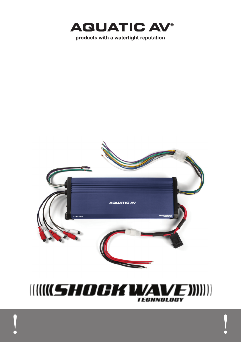
Stereo with 4x RCA full-range outputs (Front L/R & Rear L/R) .
The AD600.5 requires all six of the amplifier’s RCA inputs to be connected for all five output
channels (front left, front right, rear left, rear right and subwoofer) to have operational output.
If required, please use RCA ‘Y-connectors’ to allow all six of the amplifier’s RCA inputs to be
connected.
Always use high-quality RCA cables for best audio performance.
4.1 Low-Level (RCA) Input Wiring
Front
Rear
Sub
Front Right
Sub Right
Sub Left
Front Left
Rear Right
Rear Left
Stereo with 4x RCA full-range outputs (Front L/R & Rear L/R) and 2x RCA subwoofer output (L/R).
Front Right
Rear/Sub Right
Rear/Sub Left
Front Left
Right
Left
Stereo with 2x RCA full-range outputs (Left & Right).
Input Wiring AD600.5 COMPACT 5/4/3 CHANNEL AMPLIFIER
7www.aquaticav.com

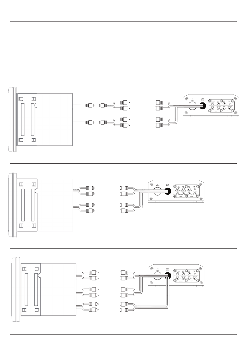
The speaker level inputs provide connections for a stereo without RCA outputs. Use them if your
source unit does not have RCA outputs.
The subwoofer outout channel will always be operational when using the high-level speaker
inputs.
4.2 High-Level (Speaker) Input Wiring
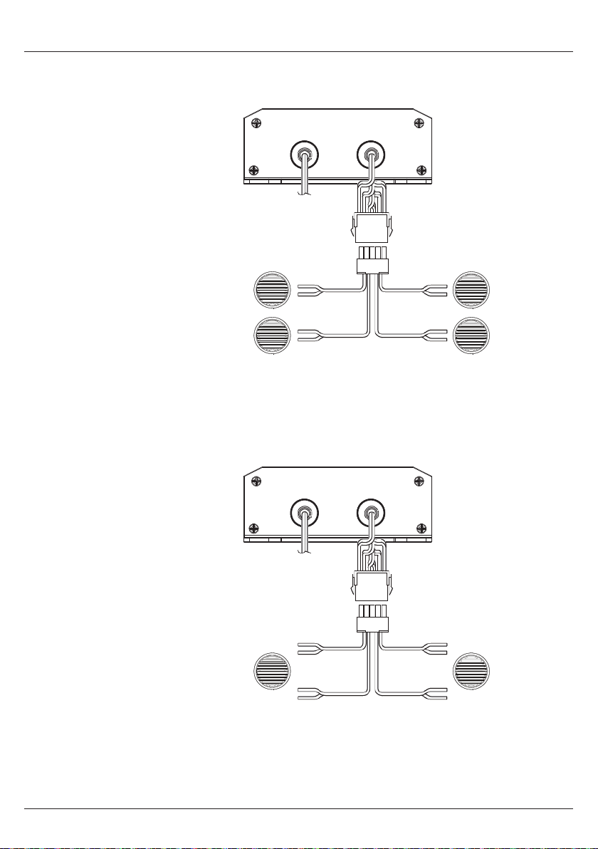
Stereo with 2x full-range speaker outputs (Front L/R).
Speaker
Outputs
White (+)
White/Black (-)
Gray (+)
Gray/Black (-)
CH1 - FL
CH2 - FR
Left
Right
Stereo with 4x full-range speaker outputs (Front L/R & Rear L/R).
Speaker
Outputs
White (+)
White/Black (-)
Gray (+)
Gray/Black (-)
Green (+)
Green/Black (-)
Purple (+)
Purple/Black (-)
CH1 - FL
CH2 - FR
CH3 - RL
CH4 - RR
FL
FR
RL
RR
Input Wiring AD600.5 COMPACT 5/4/3 CHANNEL AMPLIFIER
8www.aquaticav.com

5.1 5 Channel Mode
POWER
INPUT
SPEAKER
OUTPUT
CH1 Front Left
CH2 Front Right
CH3 Rear Left
CH4 Rear Right
White (+)
White/Black (-)
Gray (+)
Gray/Black (-)
Green (+)
Green/Black (-)
Purple (+)
Purple/Black (-)
Yellow/Black (-)
CH5 Subwoofer
Yellow (+)
POWER
INPUT
SPEAKER
OUTPUT
Bridged 1 Bridged 2
White (+)
Gray/Black (-)
Green (+)
Purple/Black (-)
Yellow/Black (-)
CH5 Subwoofer
Yellow (+)
In this application the
AD600.5 is used to power
four full-range speakers and
a subwoofer.
2 ohm and 4 ohm stable in
stereo mode.
5.2 Bridged 5 Channel Mode
In this application the
AD600.5 is used to power
two full-range speakers
with increased power and
a subwoofer. See section
5.6 for further details on
Bridge Mode operation.
2 ohm and 4 ohm stable in
bridge mode.
Output Wiring AD600.5 COMPACT 5/4/3 CHANNEL AMPLIFIER
9www.aquaticav.com
5.3 4 Channel Mode
POWER
INPUT
SPEAKER
OUTPUT
CH1 Front Left
CH2 Front Right
CH3 Rear Left
CH4 Rear Right
White (+)
White/Black (-)
Gray (+)
Gray/Black (-)
Green (+)
Green/Black (-)
Purple (+)
Purple/Black (-)
POWER
INPUT
SPEAKER
OUTPUT
Bridged 1 Bridged 2
White (+)
Gray/Black (-)
Green (+)
Purple/Black (-)
In this application the
AD600.5 is used to power
four full-range speakers.
2 ohm and 4 ohm stable in
stereo mode.
5.4 Bridged 4 Channel Mode
In this application the
AD600.5 is used to power
two full-range speakers with
increased power. See section
5.6 for further details on
Bridge Mode operation.
2 ohm and 4 ohm stable in
bridge mode.
Output Wiring AD600.5 COMPACT 5/4/3 CHANNEL AMPLIFIER
10www.aquaticav.com

5.5 3 Channel Mode
POWER
INPUT
SPEAKER
OUTPUT
CH1 Front Left CH2 Front Right
White (+)
White/Black (-)
Gray (+)
Gray/Black (-)
Yellow/Black (-)Yellow (+)
CH5 Subwoofer
In this application the
AD600.5 is used to power
two full-range speakers and
a subwoofer.
2 ohm and 4 ohm stable in
stereo mode.
5.6 Bridged Mode
Bridged Mode operation allows you to combine the power of two output channels into a single
output channel. Each bridged channel can power one full-range 4 ohm speaker.
Output Wiring AD600.5 COMPACT 5/4/3 CHANNEL AMPLIFIER
11www.aquaticav.com

6.3 Setting Crossovers
Using both the High Pass and Low Pass controls you can set the crossovers according to your
speakers frequency response. Setting the crossovers correctly allows for a louder and clearer
sound without damaging the speakers or amplifier.
For detailed information on how to tune the crossover correctly contact your local authorized
Aquatic AV dealer for tuning recommendations.
6.1 Setting Operating Level
The gain control allows the nominal operating level of the amplifier to be set from 200mV to 4V
for RCA inputs or 600mV to 10V for speaker level inputs.
After installation follow these steps and then follow section 6.4 ‘Final System Checks’.
1. Turn the gain control all the way counter clockwise.
2. Turn the ignition switch on.
3. Turn the source unit on.
4. Turn loudness off and set all tone or equalisation controls to flat positions.
5. Play music content from the source unit and set the volume to 75% of full level.
6. Slowly increase the gain control. Stop when you hear a slight distortion in the signal and
decrease the gain slightly below this threshold.
6.2 Setting Bass Boost
The amplifier includes a Bass Boost circuit which acts much like an equalizer with variable gain
fixed at 50Hz.
Use this control to tune low-frequency (bass) responses. The added boost produces rich, full bass
tones that are normally difficult to reproduce.
1. Set the Bass Boost control to off.
2. Listen to a variety of music styles and increase the bass boost control until you notice an
increase in low bass response.
If you don’t want to boost the bass frequencies, set this control to minimum.
if you hear a pop caused by speaker over exertion, lower the bass boost to prevent damage to speaker.
Amplifier Operation AD600.5 COMPACT 5/4/3 CHANNEL AMPLIFIER
12www.aquaticav.com

6.4 Final System Checks
1. Turn on the power to your audio system and ensure the stereo source unit is also powered
on.
2. The amplifier’s status LED will turn red during ‘start up’ and after a few seconds will then
turn blue to indicate the amplifier is operational.
3. Once the LED illuminates blue, wait at least two seconds then slowly increase the volume
control and listen to the audio. If you hear any noise, static, distortion or no sound at all,
check all the connections and refer to Troubleshooting. Depending on your system, the
volume may become quite loud even at low level settings. Use care when adjusting the
controls.
4. Turn the source unit’s balance controls to extreme positions (left and right) and listen to
the results. Audio output from the speakers should match the source unit settings (i.e. audio
from left speaker when balance is left).
5. Increase the volume and ensure the amplifier produces the audio at full frequencies and
without distortion. If you hear any distortion check the connections and verify that the gain
control is set correctly and/or Refer to troubleshooting.
If the LED remains red this indicates the amplifier is in Protect mode. Turn the amplifier off, check all wiring and
turn on again. If LED continues to stay red, contact your local Aquatic AV dealer.
Amplifier Operation AD600.5 COMPACT 5/4/3 CHANNEL AMPLIFIER
13www.aquaticav.com

7.1 Troubleshooting
Problem Probable Cause Solution
No Audio
Low or no remote turn-on voltage. Check remote connections at the amplifier
and source unit.
Blown amplifier fuse. Replace with a new fast-blow fuse of the
same rating.
Power wires not connected. Check battery and ground wiring at the
amplifier and check the battery connections.
Speaker leads shorted. Check speaker continuity to ground. It
should not show a common ground.
Speakers not connected or are blown. Check speaker connections at the amplifier.
Measure speaker coil impedance.
Audio cycles on and off Thermal protection circuits are
shutting the amplifier off.
Check the installation for adequate
ventilation.
Consult an authorized Aquatic AV dealer.
Distorted audio Gain is not properly set or the
speaker cones are damaged.
Review instructions for setting gain. Inspect
each speaker cone for signs of damage,
such as frozen cone or burning smell.
Amplifier fuse keeps blowing Wiring is connected incorrectly or
there is a short circuit.
Review the installation precautions and
diagram in this manual and Check all wiring
connections.
Whining or ticking noise when
engine is turned on
Amplifier is picking up alternator or
radiated noise.
Turn down input gain.
Move audio cables away from the power
wires.
Check the power and ground connections
on the amplifier and install an in-line noise
filter on the stereo’s power wires.
Check alternator and/or voltage regulator.
Test for a weak battery or add water to the
battery.
Troubleshooting AD600.5 COMPACT 5/4/3 CHANNEL AMPLIFIER
14www.aquaticav.com

Type................................................................Class-D Digital Amplifier
Output Modes...................................................Mono, Stereo, Bridge
Waterproof....................................................... Yes - IP65
Conformal Coated PCB......................................Yes
Input Channels.................................................5x RCA
Speaker Level Input..........................................5 channels
Output Channels...............................................5/4/3
Input Impedance..............................................22k (RCA), 470 Ohms (speaker)
Output Impedance (per channel)........................2 Ohms / 4 Ohms
Power Output (max)..........................................600W
Power Output (max) @ 4 Ohms, THD ≤1%..........4x 50W + 1x 200W
Power Output (max) @ 2 Ohms, THD ≤1%..........4x 75W + 1x 300W
Power Output - Bridged @ 4 Ohms, THD ≤1%.....2x 150W
S/N (A-weighted, 1W @ 4 Ohms)........................≥70dB
Frequency Response.........................................10-20kHz (1CH to 4CH), 10-250Hz (5CH)
Channel Separation...........................................≥ 48dB
Input Sensitivity (Low Level)..............................200mV to 4V
Input Sensitivity (High Level).............................600mV to 10V
Bridge Mode.................................................... Yes (CH1 - CH4)
Bass Boost Adjustment..................................... Variable 0 to +18dB (Sub CH)
Bass Boost Frequency....................................... 50Hz
High Pass Electronic Crossover (12dB/Oct.)........ Variable 50 - 250Hz
Low Pass Electronic Crossover (12dB/Oct.)......... Variable 50 - 250Hz
Current Draw....................................................<2mA standby
Gain Control Type............................................. Variable Gain Control
Ground Loop Isolation Input Circuit....................Yes
Allowable Battery Voltage.................................. 10.8V - 15.6V
Power Fuse...................................................... Yes in Power Cable
Additional Features...........................................Nickel plated connectors
LED Indicator
Remote Turn-On
Turn-On/Off Muting Circuit (Soft Mute)
8.1 Specifications
8.2 Dimensions
LOW
INPUT
HI
INPUTBASS
SUB
LEVEL
LOW
PASS EQ
PWR
PRT
LEVEL LEVEL
HIGH PASS HIGH PASS
-REAR-
-FRONT-
MIN MAX MIN MAX
50 250 50 250
MIN MAX 50 250 018dB
316.5mm
305mm
94.5mm 113mm
LOW
INPUT
HI
INPUTBASS
SUB
LEVEL
LOW
PASS EQ
PWR
PRT
LEVEL LEVEL
HIGH PASS HIGH PASS
-REAR-
-FRONT-
MIN MAX MIN MAX
50 250 50 250
MIN MAX 50 250 018dB 45.5mm
Specifications & Dimensions AD600.5 COMPACT 5/4/3 CHANNEL AMPLIFIER
15www.aquaticav.com

Aquatic AV offers a limited warranty of our products on the following terms:
Length of warranty
2 years on audio systems, electronics, speakers, and accessories (receipt required).
Coverage
This warranty covers only the original purchaser of a Aquatic AV product purchased from an
authorized Aquatic AV dealer in the United States. In order to receive service, the purchaser must
provide Aquatic AV with a copy of the receipt stating the customer name, dealer name, product
purchased and date of purchase.
Defective products
Products found to be defective during the warranty period will be repaired or replaced (with a
product deemed to be equivalent) at Aquatic AV’s discretion.
What is not covered
Damage caused by accident, abuse, improper operations, theft. Any cost or expense related to
the removal or reinstallation of product. Service performed by anyone other than an authorized
Aquatic AV service center. Any product with the serial number or tamper labels defaced, altered,
or removed. Subsequent damage to other components. Any product not purchased from an au-
thorized Aquatic AV dealer.
Limit on implied warranties
Any implied warranties including warranties of fitness for use and merchantability are limited in
duration to the period of the express warranty set forth above. Some states do not allow limita-
tions on the length of an implied warranty, so this limitation may not apply. No person is author-
ized to assume for Aquatic AV any other liability in connection with the sale of the product.
How to obtain service
You must obtain a return material authorization number (RMA) to return any product to Aquatic
AV. You are responsible for shipping charges of returned products to Aquatic AV.
Priority Customer Support & Free Extended Warranty
In order to receive the best customer support from Aquatic AV we recommend you register your
product for a free extended warranty.
Register your product for extended warranty and priority support at www.aquaticav.com/register
Please record the model and serial number[s] of your equipment in the space provided below as
your permanent record and will assist us with your factory warranty coverage. These numbers can
be found on the underside of the amplifier.
Model number[s]: Serial number[s]:
Warranty Information AD600.5 COMPACT 5/4/3 CHANNEL AMPLIFIER
16www.aquaticav.com

Product design and specification subject to change without notice. E&OE.
Doc V1.1
FCC ID:
MADE IN CHINA
FCC Statement to the User
This equipment has been tested and found to comply with the limits for a Class B digital
device, pursuant to Part 15 of the FCC Rules. These limits are designed to provide
reasonable protection against harmful interference in a residential installation. This
equipment generates, uses and can radiate radio frequency energy and, if not installed
and used in accordance with the instructions, may cause harmful interference to radio
communications. However, there is no guarantee that interference will not occur in a
particular installation. If this equipment does cause harmful interference to radio or
television reception, which can be determined by turning the equipment off and on, the
user is encouraged to try to correct the interference by one of the following measures:
1. Reorient or relocate the receiving antenna.
2. Connect the equipment into an outlet on a circuit different from that to which the
receiver is connected.
3. Increase the separation between the equipment and receiver.
4. Consult the dealer or an experienced radio/TV technician for help.
FCC Caution:
Any changes or modifications not expressly approved by the party responsible for
compliance could void the user’s authority to operate this equipment.
This device complies with Part 15 of the FCC Rules. Operation is subject to the following
two conditions: (1) This device may not cause harmful interference, and (2) this device
must accept any interference received, including interference that may cause undesired
operation
WARNING: This product contains
chemicals known to the State of
California to cause cancer, and birth
defects or other reproductive harm.
For more information: www.P65Warnings.ca.gov
California Proposition
65 Warning
FCC Statement AD600.5 COMPACT 5/4/3 CHANNEL AMPLIFIER
17www.aquaticav.com

E-mail: info@aquaticav.com
US & Canada: 1 877 579 2782
International: +1 408 559 1668
Fax: +1 408 559 0125
www.aquaticav.com
Aquatic AV
282 Kinney Drive
San Jose, CA 95112, USA
Table of contents


