ARCHITETTURA SONORA ASM2 User manual

ARCHITETTURA SONORA
AMPLIFIERS USER’S MANUAL

Last update: December 2017
Specication could be changed without notice
2
1. Important Safety Precautions 3
2. Introduction 4
3. User Instructions 4
6. Rack Mount Kit 7
7. Possible Congurations 7
8. Operation 8
9. Troubleshooting 9
10. Technical Specications 10
11. Maintenance 12
12. End-of-life Product Disposal 12
13. Warranty 12
14. Declaration of Conformity 13
4. General Informations 5
5. System Wiring 6
Index

3
1. Important Safety Precautions
This symbol indicates the presence of important user instructions and information that should be given particular attention
so as to use the product properly.
This symbol indicates the presence of “dangerous voltage” that may cause the risk of electric shock. Pay the utmost
attention and proceed cautiously.
For a correct and safe use of Architettura Sonora’s ampliers, to protect your own and
other people’s safety and to avoid invalidation of the product warranty, please read this
section carefully before operating this product.
1. Follow carefully the attached documentation and keep it for future reference.
2. Comply with the warnings.
3. Carefully unpack and store the packaging, checking that all material is in excellent conditions.
4. Do not use water near the product; do not pour water or any other liquid on the ampliers. Do not use it with wet hands or feet into the
water.
5. Do not use next to heat sources such as radiators, stoves or other similar devices.
6. Check the integrity of the mains cable. Do not tread on the cable and do not squeeze the plug.
7. Connect the plug to a grounded socket equipped with grounding. Do not tamper with the plug. If the plug supplied is not compatible with
your socket, please apply to an electrician for its replacement.
8. Connect to a mains supply with the same voltage as indicated on the back of the amplier.
9. Install the ampliers in compliance with the instructions.
10. Do not obstruct the air ducts.
11. Disconnect the appliance in case of storm and if unused.
12. Connect according to the instructions only.
13. Do not connect an input signal higher than that indicated in the manual.
14. Do not connect the amplier output to the input of another amplier.
15. Do not connect any output of the amplier to power sources such as battery, voltage supply or outlet, regardless of whether the amplier
is ON or OFF.
16. Keep the volume controls to a minimum during the amplier switching ON/OFF.
17. Do not remove the upper cover: there is a risk of electric shock.
18. Do not try to self-repair the appliance, but apply to qualied personnel.
19. Clean with a dry cloth only.
20. Careful supervision is necessary if the product is used in the presence of children or inexpert adults.
21. This product could produce sound levels which may cause hearing damage. Use the utmost care and do not operate at high volume level
or at an uncomfortable level for a long time. Consult an audiometric specialist in case of hearing loss or complaints.
WARNING

4
2. Introduction
3. User Instructions
Warning: before any audio connection keep in mind that the regular
procedure is to turn off the amplier, unplug it from the mains and
set the volume control to the minimum during start up.
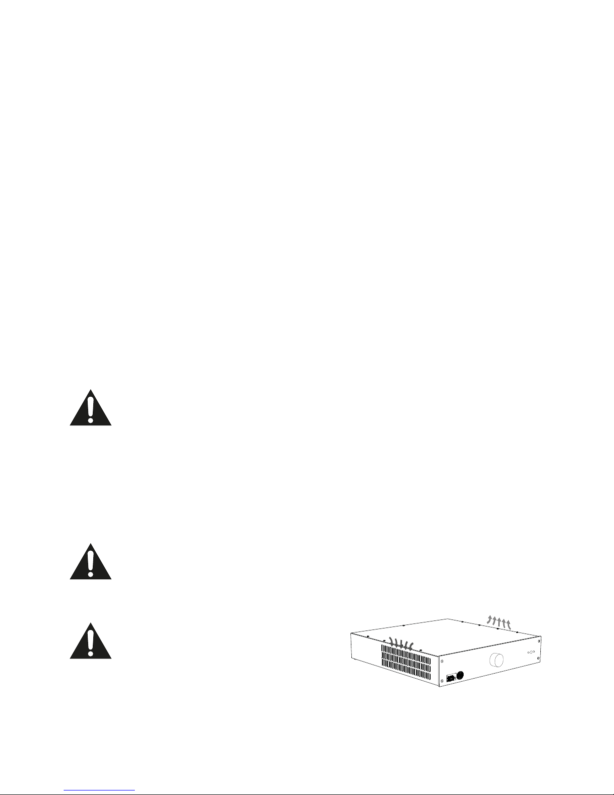
Do not block the lateral air vents!
The airow is directed through the ventilation grills on the side panels of the amplier; make sure that the ventilation grills are clear of
obstructions and pay particular attention to leave at least 20 mm from the unit's sides and the cabinet side walls.
If the amplier is installed in a rack cabinet make sure there is enough air clearance: air should easily ow through the amplier and meet
no resistance.
Thank you for purchasing this Architettura Sonora power amplier. AS ampliers are multi-channel ampliers designed specically to drive
the architectural loudspeakers manufactured by Architettura Sonora.
Please read the following directions to obtain the best results.
Architettura Sonora power ampliers feature class-D power modules, combining high sound quality and energy efciency, and preampliers
circuits based on the latest generation class-A VCA (Voltage Controlled Ampliers).
The available congurations, diversied by number of channels and available power, allow to assemble, in the most simple way, sound
systems from the most basic to the most complex.
The integrated ampliers' available power and quality make them the ideal solution to be used in any application requiring to drive a large
number of quality speakers.
Some models of ampliers come with internal DSP (Digital Signal Processor), accessible only by trained personnel and pre-programmed in
our laboratories according to the client’s instructions and requirements.
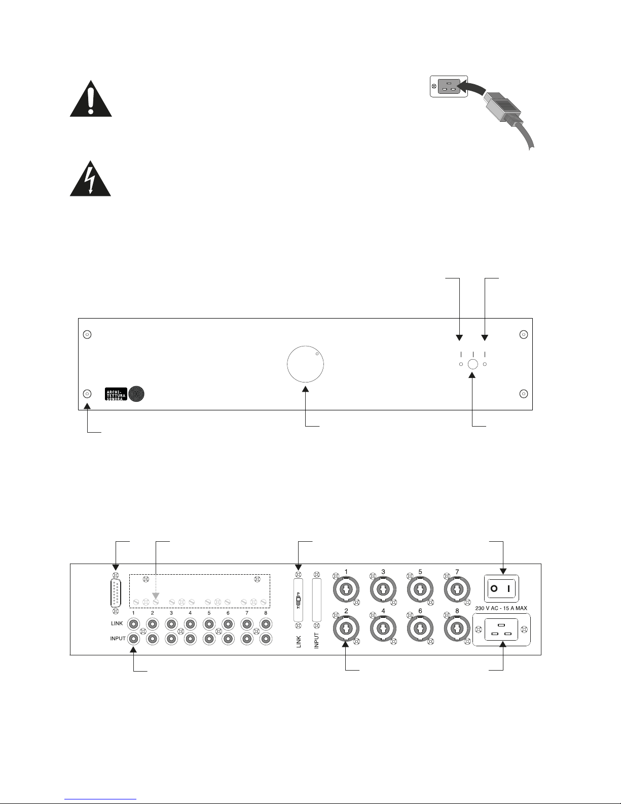
All AS ampliers have the Master Volume Control, which allows to adjust the volume of all output channels through the knob on the front panel.
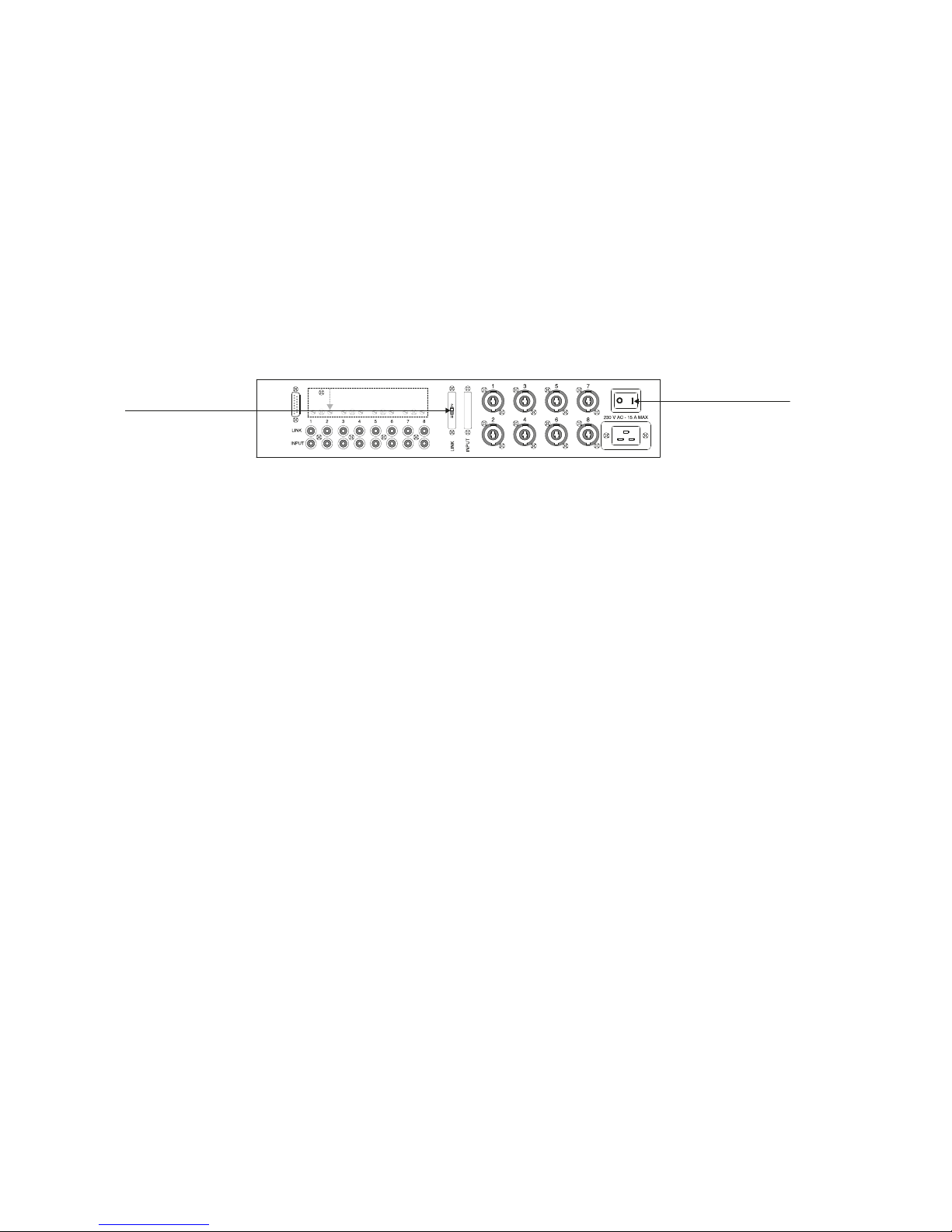
Maximum Power Consumption > Check whether there is enough mains power to supply the amplier (refer to the data at
the end of this manual). Please ensure that the voltage of the mains supply complies with the label found at the back of the amplier. Maximum
power consumption is limited solely through the internal fuses.
Cooling > Pay particular attention to the ventilation/cooling conditions of the amplier. An internal system of forced airow, by a variable
speed fan, allows cooling from the heat generated by power parts; the fan automatically runs faster when the amp is working hard.
Unpacking > IMPORTANT: Immediately inspect the package and its content in order to check whether there are any signs of damage
that may have occurred during transit. After unpacking check the product in all its parts; if you notice any damage inform your dealer
immediately. It is advisable to save the packaging materials even if the amplier shows no sign of shipping damage; you might have to return
it to Architettura Sonora or to one of its dealers. Use the original package only, which is the best way to protect the equipment from shipping
mishandling.
Check the contents of the package:
- 1 amplier;
- 1 copy of the user manual;
- 1 rack mounting brackets set (see chapter 6);
- 1 power supply cable;
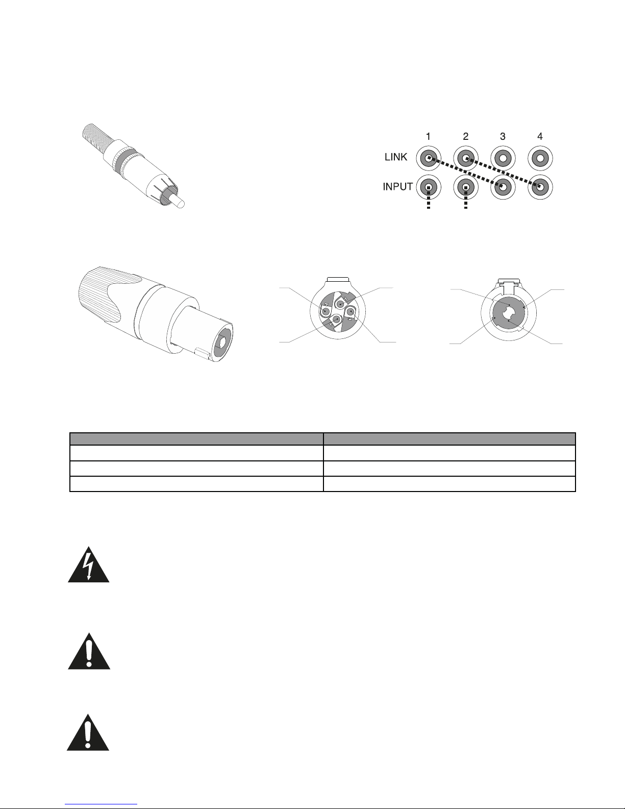
- 1 bag containing a number of Neutrik® SpeakON NL4 connectors sufcient for wiring the loudspeaker.
Installation/Assembly > The unit may be used free-standing, installed in either a rack cabinet or a ight-case box. All models
may be installed in a 19’’ standard rack stand through the proper rack mounting brackets provided into the box.
When the unit is installed in a cabinet or in a case, make sure that the ow of air, necessary for proper cooling, is not
obstructed.
Do not block the air vents on side panels.
Avoid installation in places with high temperatures, dust, excessive humidity or water next to the devices, presence of strong
magnetic elds and vibrations.
Close, using blank rack panels, any open space in the rack.
Leave the rear of the rack open. If this is not possible, install a suitable hot air exhaust system.
The high current drain of very high power ampliers requires an adequate system for AC mains power supply.
It is thus mandatory to use a suitable electrical panel, built in compliance with the applicable country-specic, technical and
safety regulations, tested by a qualied technician.

5
DATA PRG
Front Panel
Rear Panel
4. General Informations
The high current drain of the AS ampliers demand the use of an adequate
AC connector. The cord supplied with the amplier has the required characteristics.
In case it is unavailable or needs to be replaced, choose a replacement cable with equivalent specications, labeled with
the safety certication marking in force in the country of installation.
When installing the unit in places accessible to the general public, the cable insulation must be of the re-retardant,
low-smoke zero-halogen (LSZH) type. Country-specic technical regulations may apply. We suggest consulting a
qualied supplier for the cable selection.
Orient the IEC connector with the connector prongs in the socket,
then push the connector rmly into the IEC socket until fully seated.
In case the mains plug needs to be replaced, have it installed by a qualied technician, who should select a plug with the proper specications
and labeled with all suitable safety certication markings in force in the country of installation.
F. RCA unbalanced inputs and LINK outputs.
G. Channel's gain adjustment trimmers: they are covered by a protective cover and the adjustment are done (if required) at the initial
set-up. They are not intended as user-accessible controls. The user may adjust the master volume level using the front panel's
control.
H. Data Prg connector for DSP programming (accessible only by trained personnel).
I. Pro/Home switch
L. Power ampliers' output Neutrik SpeakON connectors for wiring the sonic modules.
M. AC mains inlet for power cable.
N. Mains power switch.
A. Master volume control.
B. Standard rack handles holes (racks mounting brackets provided).
C. Dual-color Stand-By power LED.
D. Dual-color Status power LED.
E. Power button.
AC Mains Power Cable > Connect AC power to the IEC socket on the back of the amplier.
NOTE: Turn off the AC power switch before connecting AC power.
Connect the AC mains plug to a suitable AC mains outlet.
B
CD
AE
M
N
F
I
H
L
G
AS - MULTI-CHANNEL POWER AMPLIFIER
POWER STATUSSTAND-BY

6
RCA connectors
5. System Wiring
Each cable conductor must have the minimum cross section shown on the following table.
The cables must be of adequate quality, with a exible insulation, suitable for the installation's environmental conditions, and with sufcient
copper section to minimize power loss.
All AS ampliers are multichannel, i.e. each output channel (speaker) has an independent input connector, which is the perfect solution to
manage different acoustic areas or to create environmental music with different sounds.
Input Connection > The connection of the music source to the amplier is via RCA connectors (Input). The same source can be
repeated using the Link outputs; by connecting with a RCA-RCA cable Link_1 to Input_2 it repeats the same source to speakers 1 and 2.
Output Connection > For a simpler approach, we recommend using 2-conductor or 4-conductor cables wired to Neutrik
speakON NL4 series plugs.
Use screened cables,
1 conductor + screen, wired to RCA pins.
ATTENTION: the ampliers are BTL (bridged) type.
The output socket’s negative terminals are not connected to ground and it does not exist any common terminal in the outputs
(both negative or positive).
DO NOT CONNECT any output terminal to any other: doing this may result in a failure of the power amplier's output stages.
ATTENTION: the output's connectors screw terminals and the output cables may be at a dangerous voltage value.
Make all wiring with the amplier switched off.
Wire the output cables before plugging the connectors to the amplier.
Complete the speakON plugs' assembly, installing the protective sleeve, before plugging them in the amplier's sockets.
Never leave any output conductor un-insulated or accessible to the hand.
Front view
1-
Rear view
1-
2-
1+
2+ 2+2-
1+
up to 20m
20m - 50m
more than 50m
Cable lenght
1,5 - 2,5 mm 2
2,5 – 3,5 mm2
4 - 6 mm2
Single conductor's cross section
NOTE: all the following drawings refers to a Neutrik NL-4 FC series SPX cable connector. Other model or other
manufacturer's connectors may have s slightly different aspect, so always refer to the pin numbers printed on the
connector's body.

7
DATA PRG
Stereo
Music
source
7. Possible Congurations
6. Rack Mount Kit
The Rack Mount Kit provides a mounting solution for AS ampliers in industry standard 19" equipment racks.
After disconnecting the amplier from electrical source, remove the felt and unscrew the plastic feet on the bottom. Align the provided “L”
shaped rack ears to the chassis holes on each side, as shown in image 1, and secure with the screws provided in the kit.
Remove, one side at a time, the Allen screws from the front panel, and align the front extension plate to the holes and to the rack ear
previously placed, then tighten to secure the screws back in position, as shown in image 2; secure rmly, do not over tighten.
Place the back extension plates aligned with the chassis holes in either side of the chassis and secure it back with the provided screws, do
not over tighten.
Stereo Conguration >
Architettura Sonora has revolutionized the multidimensional sound experience with his collection of loudspeaker and with its line of ampliers
enhancing that experience. Following some possible congurations intended as general guidelines, covering a standard listening space.
These guidelines do not cover all possible variables and factors present to a specic installation; adaptations and deviations may be required
in particular situations.
L
L
L
R
R
R
Fig.1 Fig.2
Fig.3

8
DATA PRG
Stereo
Music
source
A
Stereo
Music
source
B
DATA PRG
5.1 Processor
Music Source
8. Operation
After completion of installation and wiring, as described in the previous paragraphs, switch the amplier ON by actuating the rear mains switch (N).
"STATUS" power LED (D) indicates the status of the amplier: green everything is OK, yellow if the amplier is in "MUTE", red if one or more
of the amplier modules is off or defective.
"STAND-BY" power LED (C) indicates the status of the POWER command (E): green the amplier is enabled (ACTIVE), yellow if it is disabled
(MUTE)
Pressing the POWER button switches from the MUTE (amplier disabled) to the ACTIVE state (amplier enabled)
The rear P/H switch (I) determines the status of the amplier when turned on. It has two positions: P (Pro) and H (Home)
Multi-room / multi-source Conguration >
Room 1 > Music A
Room 2 > Music B
central
Sub
5.1 Surround Conguration >
L
L
L
R
R
RLR
AS - MULTI-CHANNEL POWER AMPLIFIER
POWER STATUSSTAND-BY
A
C
E
D

9
9. Troubleshooting
Position P > the amplier is active when switched on, after the initial delay.
The Status LED changes from yellow (mute) to green (active) automatically after the initial delay.
When turning the amplier on the Status LED is yellow for about 2 seconds (delay), or red if one or more of the amplier modules are off or
defective.
After 2 seconds: Green> amplier Active
Pressing the power button (E) > MUTE, both LED yellow, all channels in MUTE
Pressing the power button (E) > ENABLE, both LED green, All channels ACTIVE
Position H > the amplier is Mute when switched on, and must be activated by pressing the POWER button (E).
When turning the amplier on the Status LED is yellow or red if one or more channels are off or defective.
The Stand-By LED is yellow: all channels disabled.
Pressing the button Power (E) > ENABLE: both LED green, all channels ACTIVE
Pressing the button Power (E) > MUTE: both LED yellow, all channels in MUTE
The only user accessible control is the front panel master volume control (A).
Listening level adjustment is preferably done by acting on other system's control.
CONDITION: Power indicator is off.
• The amplier has lost AC power.
• The amplier is not plugged into the power receptacle.
• The amplier’s power switch is off.
CONDITION: Power indicator is bright green.
• Amplier is ready to pass a signal.
CONDITION: Power indicator is red.
• One or more power modules are off.
• One amplier channel has stopped operating.
REFER THE UNIT TO ARCHITETTURA SONORA SERVICE CENTER
CONDITION: Power indicator is blinking from green to red.
• One or more modules are operating outside their rated specications' range. Reduce the master volume’s value.
If the problem persists contact ARCHITETTURA SONORA SERVICE CENTER.
CONDITION: Amplier turns off when playing.
• Thermal failure. The amplier is too hot for safe operation. Allow amplier to cool. Check for load less than 3 ohm, and
for excessive input level. Check for proper ventilation.
CONDITION: No sound, even though the amp has power. Power led is green and
the amp is receiving an input signal.
• Speaker not connected.
• Check speakON wiring.
• Open circuit due to speaker failure.
• The input wiring is defective or unconnected.
• There is a short circuit on the amplier output. First disconnect your speakers from the affected channel(s) one by one to
determine if one of the loads is shorted.
DATA PRG
N
I

10
10. Technical Specications
Rated power output
(< 1% THD+N, 20Hz – 20kHz)
Frequency response
(± 0.3 ÷ ±0.7 dB)
THD + N at rated output power
(1W, 1kHz, 8Ω)
Damping factor
(8Ω, 100Hz)
Dynamic range
(A-weighted)
Input connectors
Ouput connectors
Led indicators
Output circuitry
DSP
Cooling
Max AC current draw
AC main connector
AC power cable
Power requirements
Main fuse
Dimensions
(W×H×D)
Net weight
Model
170-264 VAC - 45/65 Hz
Operation at 85-132 VAC is possible after internal modication.
Consult factory if needed.
170-264 VAC - 45/65 Hz
Operation at 85-132 VAC is possible after internal modication.
Consult factory if needed.
Internal master fuse: type 16 A T
(time-delayed type) 6.3 × 30 mm
Each power amplier module is protected by an independent fuse
FUSES ARE NOT USER-REPLACEABLE
Internal master fuse: type 16 A T
(time-delayed type) 6.3 × 30 mm
Each power amplier module is protected by an independent fuse
FUSES ARE NOT USER-REPLACEABLE
Unbalanced input: type RCA socket
Input sensitivity: +3 dBV (1.4 Vrms)
Input impedance: 100 kΩ
Active status: Green (ON) / Red (FAULT)
Mute status: Orange
Active status: Green (ON) / Red (FAULT)
Mute status: Orange
Thermal controlled low noise fan
Side-to-side air ow
Thermal controlled low noise fan
Side-to-side air ow
16 A @ 230 V (3450 VA) 16 A @ 230 V (3450 VA)
Panel socket type C20 (IEC 60320) – 16 A
437 × 88 × 466 mm (2RU – 19”)
On board (ASM2EVO)
NO (ASM2)
On board (ASH3EVO)
NO (ASH3)
4 pole Neutrik speakON
®
< 0.3%
> 600
119 dB(A)
20 Hz – 20 kHz
12 kg
ASM2 / ASM2EVO
2 ch × 1100 W
2 ch × 550 W
2 ch × 450 W + 1 ch × 1100 W
2 ch × 250 W + 1 ch × 550 W
Unbalanced input: type RCA socket
Input sensitivity: +3 dBV (1.4 Vrms)
Input impedance: 100 kΩ
437 × 88 × 466 mm (2RU – 19”)
4 pole Neutrik speakON
®
Class D – ICEpower Technology
®Class D – ICEpower Technology
®
<0.1% (250 W channels)
<0.3% (1100 W channel)
> 600
125 dB(A) (250 W channels)
119 dB(A) (1100 W channel)
20 Hz – 20 kHz
12 kg
ASH3 / ASH3EVO
4 Ω
8 Ω
Amplier: plug type C19 (IEC 60320) – 16 A,
Plug type IEC 7/7 hybrid,
3 conductor cable 3 × 1.5 mm2
Panel socket type C20 (IEC 60320) – 16 A
Amplier: plug type C19 (IEC 60320) – 16 A,
Plug type IEC 7/7 hybrid,
3 conductor cable 3 × 1.5 mm2

11
170-264 VAC - 45/65 Hz
Operation at 85-132 VAC is possible after internal modication.
Consult factory if needed.
Internal master fuse: type 10 A T
(time-delayed type) 6.3 × 30 mm
Each power amplier module is protected by an independent fuse
FUSES ARE NOT USER-REPLACEABLE
Active status: Green (ON) / Red (FAULT)
Mute status: Orange
Thermal controlled low noise fan
Side-to-side air ow
10 A @ 230 V (2300 VA)
On board (ASC4EVO)
NO (ASC4)
4 ch × 450 W
4 ch × 250 W
Unbalanced input: type RCA socket
Input sensitivity: +3 dBV (1.4 Vrms)
Input impedance: 100 kΩ
437 × 88 × 466 mm (2RU – 19”)
4 pole Neutrik speakON
®
Class D – ICEpower Technology
®
<0.1%
> 500
125 dB(A)
20 Hz – 20 kHz
9,2 kg
ASC4 / ASC4EVO
Panel socket type C14 (IEC 60320) – 10 A
Amplier: plug type C13 (IEC 60320) – 10 A,
Plug type IEC 7/7 hybrid,
3 conductor cable 3 × 1.0 mm2
170-264 VAC - 45/65 Hz
Operation at 85-132 VAC is possible after internal modication.
Consult factory if needed.
Internal master fuse: type 16 A T
(time-delayed type) 6.3 × 30 mm
Each power amplier module is protected by an independent fuse
FUSES ARE NOT USER-REPLACEABLE
Active status: Green (ON) / Red (FAULT)
Mute status: Orange
Thermal controlled low noise fan
Side-to-side air ow
16 A @ 230 V (3450 VA)
On board (ASHC6VO)
NO (ASC6)
6 ch × 450 W
6 ch × 250 W
Unbalanced input: type RCA socket
Input sensitivity: +3 dBV (1.4 Vrms)
Input impedance: 100 kΩ
437 × 88 × 466 mm (2RU – 19”)
4 pole Neutrik speakON
®
Class D – ICEpower Technology
®
<0.1%
> 500
125 dB(A)
20 Hz – 20 kHz
10 kg
ASC6 / ASC6EVO
Panel socket type C20 (IEC 60320) – 16 A
Amplier: plug type C19 (IEC 60320) – 16 A,
Plug type IEC 7/7 hybrid,
3 conductor cable 3 × 1.5 mm2
170-264 VAC - 45/65 Hz
Operation at 85-132 VAC is possible after internal modication.
Consult factory if needed.
Internal master fuse: type 10 A T
(time-delayed type) 6.3 × 30 mm
Each power amplier module is protected by an independent fuse
FUSES ARE NOT USER-REPLACEABLE
Active status: Green (ON) / Red (FAULT)
Mute status: Orange
Thermal controlled low noise fan
Side-to-side air ow
10 A @ 230 V (3450 VA)
NO
8 ch × 200 W
8 ch × 120 W
Unbalanced input: type RCA socket
Input sensitivity: +3 dBV (1.4 Vrms)
Input impedance: 100 kΩ
437 × 88 × 466 mm (2RU – 19”)
4 pole Neutrik speakON
®
Class D – ICEpower Technology
®
<0.1%
> 500
125 dB(A)
20 Hz – 20 kHz
10 kg
ASD8
Panel socket type C14 (IEC 60320) – 10 A
Amplier: plug type C13 (IEC 60320) – 10 A,
Plug type IEC 7/7 hybrid,
3 conductor cable 3 × 1.0 mm2

12
13. Warranty
11. Maintenance
12. End-of-life Product Disposal
The only user-reserved maintenance operations are:
- cleaning of the unit external surfaces using a soft, dry cloth (absolutely avoid the use of water, chemical detergents and solvents);
- cleaning of the side panel's ventilation grilles. If the unit is installed in a rack cabinet that must be opened using any type of tool, reserve this
operation to a qualied technician.
(Applicable in the European Union and other European countries with separate collection systems)
This marking shown on the product or its literature indicates that it shall not be disposed with other household wastes at the end of its working
life. To prevent possible harm to the environment or human health from uncontrolled waste disposal, please separate this from other types
of wastes and recycle it responsibly to promote the sustainable reuse of material resources.
User should contact either the distributor who supplied this product, or the local government or city ofce for details on where and how they
can take this item for environmentally safe recycling.
For more detailed information about recycling of this product, please contact your local city ofce, your household waste disposal service or
the supplier of the product.
This product should not be mixed with other commercial or household wastes for disposal.
Correct Disposal of this product (WEEE: Waste Electrical & Electronic Equipment)
AS ampliers are guaranteed against malfunction due to defects for a specied period, as set in the following statement, starting
from the date of original purchase. Should a malfunction occur during the warranty period, the product will be repaired or replaced
(at manufacturer’s discretion) free of charge. The transport charges, any relevant risks and miscarriages during the transport to the
service centres, are at customer’s charge. The product repaired under warranty will be returned at customer’s expense (EXW).
Warranty Terms
The warranty is valid for 2 years starting from the receipt of goods.
Architettura Sonora reserves the right, in some cases, to decide the replacement of a product with an identical or similar one. In case
of failure, the product replacement and warranty extension are excluded. The guarantee does not pay for incidental or consequential
damages, without limitation, caused to persons or property during the period of possible product inefciency.
Costs at Architettura Sonora Charge
Architettura Sonora will pay all labour and material expenses necessary for all repairs covered by the present warranty. Make sure
to have saved the original packing, otherwise the requested cardboard box will be charged to you. Supply AS with the original
invoice in order to establish the date of purchase. Do not return products to the factory without prior authorization. If the transport
of the product presents any difculty, you are kindly requested to inform the service centre on the matter and the personnel assigned
will arrange it together with you. On the contrary, the customer is responsible for transporting the product to be repaired, for
arranging its transport and for the payment of any shipping cost.
Limitation of Implied Warranties
All implied warranties, including guarantee of merchantability and suitability for particular purpose, are limited in the duration of the
present warranty. Architettura Sonora liability is limited to the repair or replacement, at its discretion, of any defective products and
is not liable for any kind of incidental or consequential damages.
Obtaining Warranty Service
To obtain the repair or replacement of the product under warranty, the customer must return the product packed in the original
cardboard box to the authorized centre, together with relevant proof of purchase: slip, bill of sale or invoice.
ARCHITETTURA SONORA
Via Poggiomoro 1 – Loc. Vallina
50012 BAGNO A RIPOLI (Firenze)
Telephone: +39-055-65721 - Fax: +39-055-6572312
Product repair, replacement or return to the customer are the only remedies provided for the customer. Architettura Sonora shall not
be liable for incidental or consequential damages including, without limitation, injuries to persons or property or loss of use.
Exclusions and Limitations
The warranty does not apply to:
a) exterior nishing and damages to electric/electronic parts resulting from negligent use of the product;
b) malfunction due to misuse/abuse of the product or due to transports without care;
c) repairing performed by unauthorized personnel;
d) modifying or tampering with amplier’s internal components;
e) product faults due to circumstances that can not be ascribed to manufacturing defects;
f) as regards to circuit components (transistors,diodes, etc...) the general terms set by the manufacturers are applied.
In addition, the warranty does not cover:
g) damages caused by accidents, product modication, negligence or wrong connection;
h) damages occurred during the transport;
i) damages resulting from failure to comply with the instructions included in the manual;
j) claims based upon any misrepresentations by the seller;

13
14. DECLARATION OF CONFORMITY
Rilasciato da : B&C speakers S.p.A.
Issued by: Via Poggiomoro, 1
50012 Bagno a Ripoli (FI)
Italy
in qualità di: Produttore
as: Manufacturer
Dichiara che i prodotti di seguito indicati:
Declares that the following products:
Prodotto : Amplicatore di potenza audio multicanale
Equipment type: Multichannel audio power amplier
Serie : AS
Family name:
modelli: ASM2, ASM2EVO, ASH3, ASH3EVO, ASC4, ASC4EVO, ASC6, ASC6EVO, ASD8
models: ASM2, ASM2EVO, ASH3, ASH3EVO, ASC4, ASC4EVO, ASC6, ASC6EVO, ASD8
ai quali questa dichiarazione si riferisce sono conformi alle seguenti norme o altri documenti normativi:
to which this declaration relates are in conformity with the following standards or other normative documents:
- Compatibilità elettromagnetica : EN55103-1: 2011
- Electromagnetic Compatibility: EN55103-2: 2011
EN61000-3-2: 2007
EN55022: 2006
EN61000-4-2: 2001
EN61000-4-3: 2006
EN61000-4-4: 2007
EN61000-4-5: 2006
EN61000-4-6: 2006
- Sicurezza dei prodotti elettrici : CEI EN:60065: 2004 ed. 8
-Electrical products safety:
e sono quindi rispondenti ai requisiti essenziali delle Direttive del Consiglio della U.E:
and they conform to the requirements of the E.U. Council Directives:
- Compatibilità elettromagnetica (2004/108/CE)
- Elettromagnetic compatiblity (2004/108/EEC)
- Direttiva bassa tensione (2006/95/CEE)
- Low voltage Directive (2006/95/EEC)
data : 2017/12/20 Firma : Lorenzo Coppini
date of issue: 2017/12/20 Signed:
Titolo: Amministratore Delegato
Title: C.E.O.

via del Fornaccio, 44 - Vallina
50012 - Bagno a Ripoli (FI) - Italy
Tel +39 055 65721
Fax +39 055 6572312
www. architetturasonora.com
ARCHITETTURA SONORA
a division of B&C SPEAKERS
This manual suits for next models
6
Table of contents