Shoe Systems Plus Supreme S-750 User manual
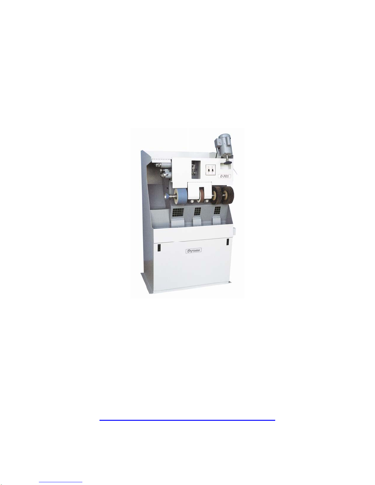
SUPREME S-750
FINISHER
Operator Manual
SHOE SYSTEMS PLUS, INC.
249 W. MAIN ST
GOSHEN, NY 10924
800-354-6278
WWW.SHOESYSTEMSPLUS.COM
1

INDEX
INTRODUCTION 3
OPERATING THE SUPREME FINISHER 3
INSTALLATION 4
ELECTRICAL CONTROL BOX 4
START-UP 5
SANDING BELT REPLACEMENT 7
SHARPENING CUTTERS 8
ACCESSORIES 10
MAINTENANCE 12
V-BELT ADJUSTMENT AND REMOVAL 15
MOTOR REPLACEMENT 16
ACCESSORIES LIST 18
2

INTRODUCTION
The Supreme Finisher is a compact, durable machine designed for fast, complete finishing
work. It will deliver efficient, dependable service when used correctly and with care. As
with any piece of specialized equipment, for best performance the manufacturer’s
instructions must be followed.
BEFORE USING THE SUPREME FINISHER, BE AWARE OF THE FOLLOWING:
Approved EYE PROTECTION should always be worn by the operator and others in the
work area.
Always DISCONNECT ELECTRICAL SOURCE before adjustments or servicing the
Finisher.
Make sure machine is PROPERLY GROUNDED.
Dust generated is FLAMMABLE – DO NOT SMOKE when using Finisher.
Keep generators and covers IN PLACE and in proper working order.
After making adjustments, REMOVE WRENCHES before operating Finisher.
NEVER leave machine running unattended – turn power off.
Observe all SAFETY WARNINGS on the machine and in this manual.
OPERATING THE SUPREME FINISHER
WARNING: Eye protection should always be worn by the operator and others in
the work area when the Finisher is in use. Eye protection is required
for protection from flying debris and dust, which could cause eye
injury.
3

INSTALLATION
The Supreme Finisher should be located on a flat, firm surface, in an area free of
obstructions that could interfere with the safe operation of the equipment. The Finisher
should be positioned and leveled on a rubber mat to obtain quiet operation with a
minimum of vibration.
WARNING: All electrical work must be performed by a qualified electrician and
must conform to all state and local ordinances.
Do not, under any circumstance, tamper with, modify, or adapt the
electrical plug and cord provided with this machine.
ELECTRICAL CONNECTIONS
Electrical connection may be made by either plugging the provided electrical cord into an
appropriately wired electrical socket, or by wiring the machine directly into an electrical
disconnect box.
WARNING: If the electrical cord, plus or wiring should become frayed or
damaged, replace it at once. Do not attempt to operate the machine
with faulty wiring as it could result in severe injury or death.
NOTE: Refer to the machinery identification plate to determine the electrical
specifications of this machine in respect to voltage, phase and
amperage requirements.
WARNING: Do not start Finisher before checking for proper sanding belt
tracking.
ELECTRICAL CONTROL BOX
The electrical control box on top of the machine houses all motor controls on the Finisher.
Each motor is automatically thermally protected. In case of overload, the relay will trip
and shut the motor off. The overload will automatically reset in a short period of time.
4

START-UP
WARNING: Eye protection should always be worn by the operator and others in
the work area when setting up the machine. Eye protection is
required for protection from flying debris and dust, which could cause
eye injury.
Before shipment, your Supreme Finisher was checked at the factory for proper adjustment
and operation. However, due to the possibility of jarring or damage during handling and
shipping, it is necessary to check that the machine is in proper working order before use.
WARNING: Before initial start up, turn sanding belt by hand to ensure that all
parts are free. Do not start Finisher before checking for proper
sanding belt tracking.
BEFORE CONNECTION TO AN ELECTRICAL POWER SUPPLY:
1. Check that all switches are off.
2. Rotate the wide sanding belt to see that all parts are free and not binding. Continue
for one complete rotation of the sanding belt, checking wide belt for tears or other
damage. You can tell that one complete revolution has been made when the joint of
the sanding belt has gone by the front pulley twice.
3. Rotate the trimmer section by moving the sole trimmer guard and turning the
feather edge back guard by hand. Observe the cutter sharpener grinding stone for
any damage.
4. Rotate the Naumkeg by hand to see that the sanding pad is not damaged and the
shaft not bent.
WARNING: As with any piece of electrical equipment, there is an ever present
hazard of electrical shock when operating or touching the Finisher.
Ensure the machine is properly grounded at all times.
Do not force the equipment. It will do the job better and safer at the
rate for which it was designed.
5

BEFORE STARTING THE SANDING BELT MOTOR, CHECK THAT THE
SANDING BELT IS TRACKING PROPERLY, AS FOLLOWS:
1. “Jog” the sanding belt motor by quickly hitting the “start” then “stop” button such
that the belt turn slowly, then stop.
2. Continue jogging the motor and check the belt to see that it stays roughly centered
on its forward pulley.
3. Tracking adjustment handle is located to the left of the sanding belt. Clockwise
rotation of the adjustments moves the belt to the left and counter clockwise rotation
moves the belt to the right. Adjust accordingly as required so that the belt is
tracking properly while running slowly.
4. Push sanding motor start button. Fine adjust the tracking of the belt at full speed.
WARNING: As the individual sanding belt wears from use, it will become
necessary to make minor tracking adjustments to keep the sanding
belt centered.
6

SANDING BELT REPLACEMENT
WARNING: Eye protection should always be worn by the operator and others in
the work area when changing sanding belts. Eye protection is
required for protection from flying debris and dust, which could cause
eye injury.
(Sanding belts can be obtained in various grits to suit your needs and are easily changed.)
WARNING: Some sanding belts are constructed to rotate in one direction only.
Check arrow inside sanding belt for rotation. Incorrect installation
can cause sudden belt failure resulting in serious injury to operator
and others in the work area.
To replace 4” wide belt:
1. Open sanding belt door.
2. Release pressure on the belt by pulling the idler wheel in front of the machine and
maintain it in place with the black idler rest.
3. Reach in access door and remove the far end of the belt off the idler first.
4. Remove built-up dust on the felt sanding wheel and on the idler metal drum.
5. To install the new sanding belt, reverse the procedure described above, then
readjust the tracking as described earlier in section “start-up”.
WARNING: Do not start Finisher before checking for proper sanding belt
tracking.
Do not operate machine with access door open.
Never leave machine running while unattended. Turn it off.
As individual sanding belt wears from use, it will become necessary to
make minor tracking adjustments to keep sanding belts centered.
7

SHARPENING CUTTERS
WARNING: Eye protection should always be worn by the operator and others in
the work area when sharpening cutters. Eye protection is required for
protection from flying debris and dust, which could cause eye injury.
Sharpen dull cutters as soon as dullness is noted to avoid poor work
and less production. More time is lost in trying to do another case
with a dull cutter than making short frequent stops to keep cutter
sharp.
The cutter-sharpener on your Supreme Finisher is for sharpening sole trimmer and top lift
cutters size no. 2 Iron through no. 36 Iron only and is not to be used for sharpening a
carbide cutter.
On the lower Shaft (top lift and heel trimming), stationary shield on outer edge of the
cutter is adjustable and can be set to trim without marking or cutting the cover on heels.
The back guard should be adjusted to the thickness of the top lift being trimmed.
To remove the trimmer cutters:
1. Remove the cutter retaining screw, M7904, and the washer, M2446 or M7131.
2. Pull cutter off the shaft.
3. To reassemble, reverse procedure.
WARNING: To minimize fire hazard, turn dust extractor off while sharpening
cutters and grind gently to minimize sparks.
TO SHARPEN TRIMMER CUTTERS PROCEED AS FOLLOWS:
1. Turn machine off.
2. With teeth facing counter clockwise, place cutter on the collar on the cutter
sharpener post.
3. Swing assembly forward and adjust thumb screw until the face of the tooth lies
alongside the flat grinding wheel surface. Be sure the other side of the wheel does
not touch the back side of the next tooth.
4. Move cutter away from the grinding wheel. Turn on the trimmer section motor.
5. Slowly move the cutter towards the grinding wheel. Try your setting and adjust
again if needed.
8

6. Manually rotate the cutter to the next tooth. Take care to grind each tooth of the
cutter the same amount.
7. Complete one revolution before adjusting for more cut.
Occasionally, the flat grinding surface on the grinding wheel will become glazed over with
a dark film that greatly reduces the grinding efficiency.
To remove this film, turn on the trimmer motor, lightly touch the grinding wheel flat
surface with a dressing stone, until film is removed.
WARNING: Do not attempt to sharpen cutter with a glazed or chipped wheel. A
glazed wheel requires so much pressure that the cutter teeth are liable
to be burned.
Do not attempt to sharpen carbide trimmer cutters with cutter-sharpener.
9

ACCESSORIES
WARNING: Eye protection should always be worn by the operator and others in
the work area when using the accessories supplied with the Supreme
Finisher. Eye protection is required for protection from flying debris
and dust, which could cause eye injury.
1 3/8” KEY WHEEL
TO OPEN THE KEY WHEEL:
1. Insert wrench fully into the locking mechanism.
2. Grasp shaft with one hand and push down on wrench with other hand. Wheel is in
open position when the yellow brass piece opens, or separates from the small cam
into which you have inserted the wrench.
IMPORTANT: IF WHEEL DOES NOT OPEN AFTER APPLYING PRESSURE
DOWNWARD, USE THE PALM OF YOUR HAND TO SLAP DOWN THE WRENCH.
This difficulty occurs when using heavier grit abrasives.
TO APPLY ABRASIVE STRIP IN KEY WHEEL
1. Cut abrasive strip sufficiently long to fit into the open mechanism. Be sure to leave
a slight crown of about ¼” at the opening.
DO NOT FEED ABRASIVE TOO TIGHTLY INTO MECHANISM, SINCE THE
WRENCH WILL PULL ABRASIVE IN FOR YOU.
BRUSHES ON QUICK CHANGE BAYONET FITTING
The right end of the sanding shaft is machined to accommodate bayonet fitting (quick
change). Your brown and black brushes are installed on one of these. Extra tools and
sanding wheels are available on request. See the list at the end of this book.
When removing the quick change fittings, use the special spanner wrench supplied with the
machine. To remove, engage the spanner in the hole near the end of the bayonet fitting and
apply a sharp rap downward. Before putting on a fitting be sure the machine surfaces are
clean. Hand tightening is sufficient to hold the fitting in proper position.
N.B. When properly mounted, the sanding wheel adaptor will tighten itself by rotating it
in the socket in the opposite direction of the sanding belt rotation.
WELT BRUSH, STITCH PICKER AND EDGE IRON
10

A welt brush, stitch picker and edge iron are optional accessories and can only be used on
the right end of the brush shaft. Each accessory locks on the brush shaft by rotating it in a
clockwise direction.
WARNING: Failure to properly mount the brushes on the adaptor will result in the
brushes flying apart and possible injury to the operator and others in
the work area.
These quick change accessories should be properly engaged on the
shaft to ensure safe operation. Make sure pin on shaft engages the
adaptor correctly.
Lock welt brush, stitch picker and edge iron down by turning the
adaptor in the opposite direction of shaft rotation.
11

MAINTENANCE
A properly maintained machine will give you years of satisfactory service, whereas an
abused machine will not. We strongly recommend that you observe the following
procedures for your own benefit and safety.
WARNING: Eye protection should always be worn by the operator and others in the
work area when servicing the machine Eye protection is required for
protection from flying debris and dust, which could cause eye injury.
DAILY AND WEEKLY MAINTENANCE
1. Clean your Supreme Finisher daily.
2. Shake dust bag and empty dust drawer daily.
After cleaning the machine, turn dust extraction motor off. While the motor is
coasting to a stop, shake bag vigorously.
Open the front door and remove the large dust tray, remove dust.
Check seal sound drawer and replace if damaged or if it is not sealed properly.
When the dust drawer is full, dust may spill when the drawer is removed. Vacuum
out the bottom of the machine before replacing the drawer for the last time.
The cleaner you keep the dust bag, the less likely you are to burn a hole in them. Failure to
shake the dust bag and empty the dust drawer daily will only increase this likelihood, but
also cause a significant loss of dust extraction from the sanding, trimming and brushing
areas.
3. Check grindstone condition on trimmer section and replace if badly worn, chipped
or otherwise damaged.
4. Check trimmer cutters condition daily.
Check for wear on hardened steel cutters and sharpen if necessary. (See cutter
sharpening)
Check for broken teeth on the carbide cutter, if supplied with your machine, and
replace cutter.
WARNING: Dust from Finisher is combustible. Do not smoke while cleaning the
machine and dust collector.
12

Damaged dust bag or dust drawer seals will allow the escape of
combustible materials causing a fire hazard around the machine.
Check damaged parts. Before further use of a tool, guard or other
part that is damaged, check carefully to determine that it will operate
properly and perform its intended function. Check for mounting or
any other condition that may affect its operation. A tool, guard or
other part that is harmfully damaged should be properly repaired or
replaced.
If the electrical cord, plug or wiring should become frayed or
damaged, replace it at once.
Replace all doors before operating the machine.
Do not operate machine with sander housing door open.
After making adjustments, remove all wrenches and other tools before
operating the Finisher.
Use extra caution when starting the Finisher for the first time after
installing a new tool or part.
MONTHLY MAINTENANCE
1. Check the felt and rubber sanding pulleys surface for any accumulation of dust.
Clean if necessary. Replace the wheel if worn.
2. V-Belts – Check tension and adjust if necessary.
3. Check and clean the sole trimmer and top lift trimmer insuring proper operation
and adjustments.
4. Check for proper opening and closing of all dust dampers, removing and cleaning
any accumulation around the openings.
13

LUBRICATION
Your Supreme Finisher is equipped with sealed bearings throughout, which should be
replaced if they ever wear out.
Other parts should not require any lubrication, only cleaning the parts is required.
Lubrication will only attract dust and would be more harmful than helpful.
14

V-BELT ADJUSTMENT AND REMOVAL
All V-Belts on the Supreme Finisher should be checked monthly for proper tension and
general condition. Loose V-Belts will decrease the power available to the various tools and
lower the efficiency of your Finisher.
If you discover a worn or frayed belt, replace it now so it won’t break at an inconvenient
time.
WARNING: Disconnect electrical power supply before working on the machine.
TO CHECK V-BELT TENSION:
1. Disconnect the electrical power supply.
2. Check the tension of the V-belt running to the motor; it should depress
approximately ½” when pressed in the middle with moderate force.
3. Rotate the V-belts by hand, visually inspecting the belts for damage.
4. If tensions or conditions are bad, adjust tension or replace V-belt.
WARNING: Do not over tighten V-belts, as to do so will cause rapid belt wear and
premature bearing failure.
After making adjustments, remove all wrenches and other tools before
operating the Finisher.
15

MOTOR REPLACEMENT
WARNING: Motor replacement requires working with electrical wiring and can be
hazardous. If you are not familiar with electrical procedures, please
call a qualified electrician.
DUST EXTRACTOR MOTOR
The dust extractor motor can be easily removed from the front of the machine.
To remove the motor, these directions should be followed.
1. Disconnect the electrical power supply.
2. Remove motor electrical box plate and observe the electrical wires connected.
3. Mark the electrical wires to the motor such that you will be ABSOLUTELY
CERTAIN where to reconnect them to the new motor.
4. Disconnect the electrical wires and the connector on the motor box.
5. Remove the eight (8) nuts and washers holding the motor plate to the machine.
6. Remove entire assembly of motor plate, motor and blower wheel from the machine.
7. Loosen the two (2) screws on the fan.
8. Pull the blower wheel off of the shaft.
9. Remove the four (4) screws that hold the motor to the motor plate.
10. Reassemble with new motor in reverse order of above.
11. Reconnect the power supply.
12. Turn the blower motor on and place your hand near a dust extraction port to see
whether the blower is not running backwards.
If you do not already know how to fix this without referring to this manual, call a
qualified electrician.
WARNING: Be absolutely certain to reconnect the electrical wire to the proper
terminals.
Failure to do so can result in improper motor rotation, a ruined
motor, fire, or injury to yourself.
16

OTHER MOTORS
To remove the motor, these procedures should be followed:
1. Disconnect the electrical power supply.
2. From the rear of the machine, remove the four (4) screws, nuts, and washers holding
the motor. Remove V-belt.
3. Disconnect the electrical wiring by removing the electrical plate on the end of the
motor. Mark the electrical plate on the end of the motor. Mark the electrical wires
to the motor such that you will be ABSOLUTELY CERTAIN where to reconnect
them on the new motor.
4. Reassemble with new motor in reverse order to the above procedures.
NAUMKEG MOTOR
To remove the Naumkeag motor, these procedures should be followed:
1. Disconnect the electrical power supply.
2. Remove four (4) screws, nuts and washers that hold motor to swivel plate. Remove
motor.
3. Loosen set screw on Naumkeag shaft and remove shaft.
4. Reassemble with new motor in reverse order to above procedures.
17

ACCESSORIES FOR SUPREME S-750
7" PNEUMATIC CONTOUR SANDER (A-24)
8" X 2" YARN BRUSH (A-2)
8" HORSE HAIR WITH LEATHER BURNISHER (A-3)
8" X 2" HORSE HAIR BRUSH BLACK OR BROWN (A-4)
5" WIRE BRUSH (A-5)
5" X 2" GRINDING STONE (A-6)
FLAT WHEEL 3" DIAM. 1" WIDE 120 GRIT(A-7)
6" FLAT EMERY WHEEL 120 OR 180 GRIT (A-8)
8" X 2" LAMINATED CLOTH WHEEL (A-9)
6" WELT BRUSH (A-10)
PROTECTED EDGE SANDING WHEEL 1 3/8" X 4"(A-11)
FS SANDING WHEEL 2 ½" X 5" (A-12)
BOTTOM SANDING WHEEL 4 ½" WIDE (A-13)
FS SANDING WHEEL 1 3/8" X 5" (A-16)
B SANDING WHEEL 1 3/8" X 5" (A-17)
NAUMKEAG HEAD (A-20)
HEEL BREASTER FOR RIGHT OR LEFT SIDE (A-21 R OR L)
1 ¼" X 2 ½" SANDING TUBE (A-22)
3" X 4" WIDE EXPANDING WHEEL (A-1)
8" X 1 SCOTCH BRITE WHEEL (A-25)
8" X 2" SCOTCH BRITE WHEEL
5" LAMINATED CLOTH WHEEL (A-30)
8" X 2" FELT BURNISHER (A-31)
STRAIGHT BAYONET THREADED ½" – 20 (A-32)
STRAIGHT BAYONET THREADED 5/8" – 11 (A-33)
CURVED LEATHER BURNISHER (A-34)
8" DISCOUNT SANDER (A-35)
CHANNEL WHEEL 1" THICK FOR BRACE GROOVE
CARBIDE WHEEL 2" WIDE, AIR COOLING
CARBIDE WHEEL 4" WIDE, AIR COOLING
CHUCK DRILL 3/8" W/T KEY
TRAUTMAN FITTING 3", THREAD 1/2-13 OR 5/8-11 (FOR S-240)
TRAUTMAN FITTING 8", THREAD 1/2-13 OR 5/8-11 (FOR S-500)
TRAUTMAN FITTING 12", THREAD 1/2-13 OR 5/8-11 (FOR S-240)
18
Table of contents
Other Shoe Systems Plus Finisher manuals

Popular Finisher manuals by other brands

Ricoh
Ricoh SR3300 Field service manual

Kyocera Mita
Kyocera Mita DF-75 Service manual

Lincoln
Lincoln 1961 Operator's manual

Utax
Utax DF 791 Service manual

Alliance Laundry Systems
Alliance Laundry Systems UL24A118 Installation & operation

Fayat Group
Fayat Group DYNAPAC F1800C Operation & maintenance manual


