Konica Minolta FS-534 User manual

E-1
INSTALLATION MANUAL
A3EP-9550-02
FS-534 Finisher
Caution:
Lifting the machine in an awkward position or
transporting it in a poorly balanced position could
result in personal injury. When transporting the
machine, assign an adequate number of persons
to the job and ensure that each person can take a
good position of not being excessively loaded.
(mass: approx. 40 kg (88-3/16 lb))
I. Accessory parts
No. Name Shape Q’ty
1. Horizontal
transport unit
1
2. Sensor unit*2
1
3. Exit tray (upper)
1
4. Exit tray (lower)
1
5. Staple cartridge
1
6. Mounting
bracket A*1
1
A3EPIXC001DA
A2YVIXC002DA
A3EPIXC002DA
A3EPIXC003DA
A3EPIXC004DA
A3EPIXC005DA
7. Mounting
bracket B*1
1
8. Mounting
bracket C*2
1
9. Mounting
bracket D*2
1
10. Mounting
bracket E*2 1
11. Mounting
bracket F
1
12. Mounting
bracket G
1
13. Guide plate A*1
1
14. Guide plate B*1
1
15. Wire saddle*2
1
No. Name Shape Q’ty
A3EPIXC006DA
A3EPIXC007DB
A3EPIXC008DB
A3EPIXC009DA
A3EPIXC051DA
A3EPIXC052DA
A3EPIXC010DA
A3EPIXC011DA
A3EPIXC055DA
Applied Machines: C754/C654/C554/C454/C364/C284/C224
COLOR MFP: 75 ppm/65 ppm/55 ppm/45 ppm/36 ppm/28 ppm/22 ppm
Product Code: A2X0/A2X1/A2XK/A4FJ/A161/A4FK/A4FM

E-2
*1 This part is used only when the finisher is
installed to C754/C654.
*2 This part is used only when the finisher is
installed to C554/C454/C364/C284/C224.
*3 Ten screws are used when the finisher is installed
to C754/C654.
Four screws are used when the finisher is
installed to C554/C454/C364/C284/C224.
Note:
• Before installing this finisher to C554/C454/
C364/C284/C224, the paper feed cabinet PC-
110, PC-210, PC-410, or the desk DK-510
needs to be installed in advance.
• This manual provides the illustrations of the
accessory parts and machine that may be
slightly different in shape from yours. In that
case, instead of the illustrations, use the
appearance of your machine to follow the
installation procedure. This does not cause any
significant change or problem with the proce-
dure.
• If none of the later steps instruct you to use the
parts including screw and cover that you
removed following the instructions described in
this manual, discard them.
II. Confirmation before installation
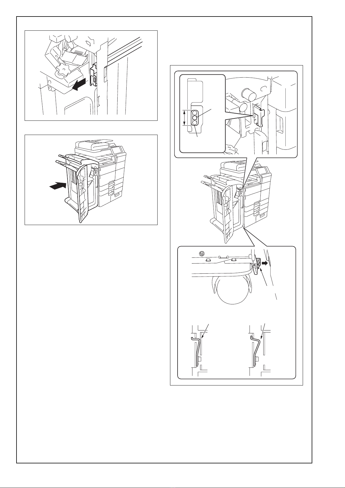
1. To move the finisher, be sure to push it in the
directions of the arrows as shown in the illustra-
tion. (Precaution against falling of the finisher.)
2. Choose a horizontal and stable floor for installing
the machine.
3. The packaging material should not be reused for
repacking.
4. When installing the optional punch kit and saddle
stitcher, attach them to the finisher first, and then
attach the finisher to the main unit.
16. Mounting screw
1
17. Screw A*3
10
18. Screw B*2
1
19. Screw C*2
5
20. Screw D
2
21. Installation
manual
1
set
After unpacking, be sure to get rid of the
packaging materials and keep them out of
the reach of children.
Putting the head in the plastic bag
involves danger of suffocation.
No. Name Shape Q’ty
A0HRIXC011DA
9646
9738
9J08IXC075DA
9654
4980IXC019DA
A3EPIXC012DA

E-3
III. Installation procedures
Note:
The parts to be used and the procedure for install-
ing this option depend on the type of the main unit
to which this option is installed. Please go to one
of the following pages that correspond to the type
of your main unit.
• When installing this option to C754/C654: E-3
• When installing this option to C554/C454/C364/
C284/C224: E-5
<When installing this option to C754/C654>
1. Turn off the machine and unplug the power cord
from the power outlet.
2. Remove the user’s guide holder from the main
unit.
3. Remove the output tray if it is mounted on the
main unit.
Note:
For the output tray removal procedure, see the
installation manual for output tray OT-503.
4. Attach the mounting bracket F to the mounting
bracket A. (One supplied screw D)
5. Attach the mounting bracket G to the mounting
bracket B. (One supplied screw D)
6. Remove the protective tape of the horizontal
transport unit.
7. Remove the cover shown in the illustration from
the back of the horizontal transport unit. (Two
screws)
A2Y1IXC010DA
A3EPIXC036DB
A3EPIXC037DB
A3EPIXC014DA
A3EPIXC038DA

E-4
8. Remove the cover shown in the illustration.
(Three screws)
9. Remove the cover shown in the illustration from
the front of the horizontal transport unit. (Two
screws)
10. Attach the guide plate A to the horizontal trans-
port unit by fitting the two tabs into the slots.
11. Attach the guide plate B. (Two screws removed
in step 9)
12. Attach the supplied mounting bracket A (front) to
the left side of the main unit. (Three supplied
screws A)
13. Attach the supplied mounting bracket B (rear).
(Three supplied screws A)
A3EPIXC039DA
A3EPIXC040DA
A3EPIXC041DA
A3EPIXC042DA
A3EPIXC043DA
A3EPIXC044DA

E-5
14. Remove one knockout (front) from the lower left
side of the main unit with nippers.
15. Mount the horizontal transport unit to the main
unit. (Two supplied screws A)
* For the following procedure, go to step 24 in
Page E-8.
<When installing this option to C554/C454/C364/
C284/C224>
1. Turn off the machine and unplug the power cord
from the power outlet.
2. Remove the user’s guide holder from the main
unit.
* When installing this option to C554/C454, the fol-
lowing steps 3 to 8 are performed only if the
optional output tray OT-506 is installed.
3. Open the front door of the main unit.
4. Remove the upper left cover from the main unit.
(Three screws)
5. Remove the output tray from the main unit.
A2Y1IXC022DA
A3EPIXC045DA
A3EPIXC013DA
A3EPIXC035DA
A2YVIXC004DB

E-6
6. Reattach the upper left cover removed in step 4
to the main unit. (Three screws)
7. Close the front door of the main unit.
8. Remove the guide from the main unit.
9. Remove the cover shown in the illustration from
the main unit. (Two screws)
10. Remove the harness shown in the illustration
from the wire saddles of the main unit.
11. Peel the seal off the cover removed in step 9 as
shown in the illustration.
12. Attach the supplied sensor unit to the main unit
by fitting the two tabs into the slots.
13. Secure the sensor unit with the supplied screw
B.
A2YVIXC005DA
A2YVIXC006DA
A3EPIXC058DA
Harness
A3EPIXC059DA
A2YVIXC011DA
A2YVIXC012DA

E-7
14. Connect the sensor unit’s connector to the con-
nector of the harness removed in step 10.
15. Route the harness through the two wire saddles
and the edge cover.
16. Attach the mounting bracket F to the mounting
bracket C. (One supplied screw D)
17. Attach the mounting bracket G to the mounting
bracket D. (One supplied screw D)
18. Reattach the cover removed in step 9 to the
main unit. (Two screws removed in step 9)
19. Remove the protective tape of the horizontal
transport unit.
20. Attach the supplied mounting bracket C (front) to
the left side of the main unit. (Two supplied
screws C)
A2YVIXC013DA
A2YVIXC014DA
A3EPIXC053DB
A3EPIXC054DB
A3EPIXC014DA
A3EPIXC015DA

E-8
21. Attach the supplied mounting bracket D (rear).
(Two supplied screws C)
22. Attach the supplied mounting bracket E to the
left side bottom of the main unit. (One supplied
screw C)
23. Mount the horizontal transport unit to the main
unit. (Two supplied screws A)
24. Remove the protective tape and the protective
materials from the finisher.
25. Open the front door of the finisher.
26. Set the supplied staple cartridge in the stapler
unit.
A3EPIXC016DA
A3EPIXC017DA
Mounting bracket E
A3EPIXC018DA
A3EPIXC050DA
A3EPIXC049DA
A3EPIXC019DB

E-9
27. Remove the protective tape.
28. Remove the screw shown in the illustration and
remove the label from the finisher.
29. Remove the plate shown in the illustration from
the lower right side of the finisher. (One screw)
30. Reattach the plate removed in step 29 in the ori-
entation shown in the illustration. (One screw
removed in step 29)
31. Attach the supplied exit tray (lower) to the fin-
isher. (Two supplied screws A)
32. Insert the supplied exit tray (upper) into the fin-
isher.
33. Connect the horizontal transport unit connector
to the connector located at the rear of the right
side of the finisher.
A3EPIXC020DB
Label
A3EPIXC021DA
A3EPIXC022DA
A3EPIXC023DA
A3EPIXC024DA
A3EPIXC025DB

E-10
34. Open the finisher front door and pull the lever.
35. Install the finisher to the main unit.
36. Verify items ➀and ➁below.
➀The plate spring of the plate installed in step 30
is contacted with the main unit.
➁When the lever that was pulled out in step 34 is
pushed back, the finisher’s screw hole is within
the range of lever’s mounting hole.
* If there are any problems after verification, con-
duct the following steps (1) to (8).
A3EPIXC026DB
A3EPIXC027DC
A3EPIXC060DA
Screw
hole
Mounting hole
on the lever
➁
➀
< OK >
Contacted Not contacted
< NG >
Plate spring

E-11
(1) Disconnect the connector, and remove the fin-
isher from the main unit.
(2) Remove the cover from the caster of the fin-
isher. (Two screws)
(3) Remove the rear cover from the finisher. (Eight
screws)
(4) Adjust the height of the four casters.
(5) Double check the verification items ➀and ➁.
* If there are any problems, go back to (4) and
readjust the caster height.
(6) To install the covers and other parts removed
in step (2) to (3), reverse the removal proce-
dure.
(7) Plug in the connector removed in step (1).
(8) Install the finisher to the main unit.
37. Push the lever back to its original position.
Secure the finisher to the main unit. (One sup-
plied mounting screw)
38. Close the front door of the finisher.
A3EPIXC029DC
A3EPIXC030DA
A3EPIXC031DB
A3EPIXC032DA
A3EPIXC061DA

E-12
39. Remove the cover shown in the illustration from
the back of the main unit. (One screw)
40. Plug in the two connectors of the finisher. Fit the
head of the cable tie into the mounting hole on
the main unit.
41. Attach the supplied wire saddle to the location of
the finisher as shown in the illustration.
Route the harness of the finisher through it.
Note:
Perform this step only when installing the finisher
to C554/C454/C364/C284/C224.
A3EPIXC046DA
<When installing this option to C754/C654>
<When installing this option to
C554/C454/C364/C284/C224>
A3CFIXC008DA
A3EPIXC047DA
<When installing this option to C754/C654>
<When installing this option to
C554/C454/C364/C284/C224>
A2YUIXC022DA
Connector
Cable tie
Connector
Cable tie
A3EPIXC056DA
Wire saddle

E-13
42. Reattach the cover removed in step 39.
(One screw)
Note:
• Be careful not to pinch the harness.
• When installing this option to C554/C454/C364/
C284/C224, insert two tabs A into the holes on
the main unit cover first.
Then fit two tabs B into the holes.
43. Install the user’s guide holder removed in step 2
as shown in the illustration.
A3EPIXC057DA
Tab B
Tab A
A3EPIXC034DB
Table of contents
Other Konica Minolta Finisher manuals

Konica Minolta
Konica Minolta SD-505 User manual

Konica Minolta
Konica Minolta FS-533 User manual

Konica Minolta
Konica Minolta FS-523 User manual

Konica Minolta
Konica Minolta FS-518 User manual

Konica Minolta
Konica Minolta SD-511 User manual

Konica Minolta
Konica Minolta Magicolor 5550 User manual

Konica Minolta
Konica Minolta FS-528 User manual

Konica Minolta
Konica Minolta FS-501 User manual

Konica Minolta
Konica Minolta FS-511 User manual