SHOOTING TECHNOLOGY ADM User manual

Data 02/04/21
TECHNIQUE ENGINEERING di Arturo Busin & C snc P. I./ C.F./ Reg. Imp. 03122570249 REA 300945 (VI)
Via M. Corner 2/4 - 36016 - Thiene (VI) ITALY tel. +39 (0)445 576528 info@technique-engineering.it
Pag. 1 di 29
MANUALE D’USO /
USER MANUAL
ADM Decapsulatrice Automatica
ADM Automatic Decapping Machine
ISTRUZIONI ORIGINALI
TRANSLATION OF THE ORIGINAL INSTRUCTIONS
PRIMA DELL’USO LEGGERE LE INFORMAZIONI COMPLETE SUL SITO www.shooting-tech.com o richiederle al venditore
BEFORE USE READ ALL GENERAL WARNINGS
www.shooting-tech.com
or ask them to seller
Tutte le informazioni in questa pubblicazione si basano sulle più recenti informazioni sui prodotti disponibili al momento della loro approvazione per la
stampa. Technique Engineering (T.E.) si riserva il diritto di apportare modifiche in qualsiasi momento senza preavviso e senza incorrere in alcun obbligo.
Le eventuali illustrazioni rappresentate sono usate per mostrare i principi importanti e procedure . Esse potrebbero non rappresentare esattamente il
prodotto corrente .Nessuna parte di questa pubblicazione può essere riprodotta senza autorizzazione scritta. E 'obbligatorio scaricare il presente manuale
dal sito web SHOOTING TECHNOLOGY oppure richiederlo al vostro rivenditore o a T.E. direttamente.
All information in this publication is on the latest product information available at the time of printing. Technique Engineering (T.E.) reserves the right to
make changes at any time without notice. Illustrations in the manual are used to show the basic principles of operation and work procedures. They may not
represent the actual product exactly in detail. No part of this publication may be reproduced without written permission. It is mandatory to download it
from the SHOOTING TECHNOLOGY web site or to your dealer or T.E. directly.

Data 02/04/21
TECHNIQUE ENGINEERING di Arturo Busin & C snc P. I./ C.F./ Reg. Imp. 03122570249 REA 300945 (VI)
Via M. Corner 2/4 - 36016 - Thiene (VI) ITALY tel. +39 (0)445 576528 info@technique-engineering.it
Pag. 2 di 29
Codice manuale –Manual Code : DEC_057
Sommario/ Summary
1PREFAZIONE / PREFACE ........................................................................................................................ 3
2INFORMAZIONI GENERALI / GENERAL INFORMATIONS..................................................................... 3
2.1. Definizioni e simboli/ Definitions and symbols...................................................................................... 3
2.2. Identificazione del fabbricante/ Identification of the manufacturer ....................................................... 5
3CARATTERISTICHE ED INFORMAZIONI TECNICHE/ CHARACTERISTICS AND TECHNICAL
INFORMATIONS................................................................................................................................................ 7
3.1. Riferimenti normativi/Standard References............................................................................................. 7
4DESTINAZIONE D’USO- AVVERTENZE / DESTINED USE- WARNINGS............................................. 8
5INSTALLAZIONE ED IMMAGAZZINAGGIO/ INSTALLATION AND STORAGE....................................... 9
5.1. Guida al montaggio/ Assembly Guide................................................................................................ 10
6ISTRUZIONI PER L’USO / USER INSTRUCTIONS............................................................................... 13
6.1. FUNZIONE DEI TASTI / CONTROL PUSH-BUTTONS PANEL FUNCTIONS................................. 14
6.2. CAMBIO CALIBRO BOSSOLI / CALIBER CHANGES ...................................................................... 15
6.3. SOSTITUZIONE PUNZONE / DECAPPING PUNCH SOBSTITUTION ........................................... 17
7MANUTENZIONE / MAINTENANCE...................................................................................................... 21
8MESSAGGI CENTRALINA / DRIVER UNIT MESSAGES....................................................................... 23
9INCONVENIENTI / MALFUNCTIONINGS............................................................................................... 24
10 SMALTIMENTO DELL’APPARECCHIATURA A FINE VITA/END OF LIFE DISPOSAL EQUIPMENT .. 26
11 ALLEGATO/ ANNEX 1. Modulo richiesta intervento –parti di ricambio/ Spare parts module................. 27
12 ALLEGATO/ ANNEX 2. Elenco parti di ricambio apparecchiatura/ Spare part list ................................ 28
13 GARANZIA/ WARRANTY.................................................................................................................... 28

Data 02/04/21
TECHNIQUE ENGINEERING di Arturo Busin & C snc P. I./ C.F./ Reg. Imp. 03122570249 REA 300945 (VI)
Via M. Corner 2/4 - 36016 - Thiene (VI) ITALY tel. +39 (0)445 576528 info@technique-engineering.it
Pag. 3 di 29
1PREFAZIONE /
PREFACE
Gentile Cliente,
La ringraziamo per la preferenza riservata alla nostra apparecchiatura.
La invitiamo a seguire scrupolosamente le indicazioni riportate nel presente manuale, questo Le sarà di valido aiuto per
l’utilizzo ottimale e per mantenere inalterate nel tempo le caratteristiche della Sua apparecchiatura.
I paragrafi successivi riportano le informazioni tecniche e le modalità d’uso della macchina
Dear Customer,
Thank you for the preference given to our equipment.
We encourage you to carefully follow the instructions given in this manual, that will be of great help for the optimal use and
to maintain over time the characteristics of your equipment.
The following paragraphs set out the technical information and directions for use of the machine.
2INFORMAZIONI GENERALI /
GENERAL INFORMATIONS
Il presente Manuale d’uso è parte integrante dell’apparecchiatura ed ha lo scopo di fornire tutte le informazioni necessarie
per:
La corretta sensibilizzazione degli operatori alle problematiche di sicurezza.
La manipolazione dell’apparecchiatura, imballata e disimballata in condizioni di sicurezza.
La corretta installazione dell’apparecchiatura.
Il corretto uso in condizioni di sicurezza.
Interventi di manutenzione, in modo corretto e sicuro.
Smantellare l’apparecchiatura in condizioni di sicurezza e nel rispetto delle norme vigenti a tutela della salute dei
lavoratori e dell’ambiente.
This User's Manual is an integral part of the equipment and its purpose is to provide all the information necessary for the:
Proper awareness of safety issues.
Correct and safe handling of the equipment, including unpacking.
Correct installation of the equipment
Proper use in safety.
Maintenance, carried out correctly and safely.
Dismantling of the equipment in a safe condition and in compliance with applicable standards in order to protect
the health of workers and the environment.
2.1. Definizioni e simboli/
Definitions and symbols
Riportiamo di seguito una serie di definizioni, terminologie e simboli utilizzate nella stesura di questo manuale.
Below is a set of definitions, terminology and symbols used in the preparation of this manual.
2.1.1. Definizioni/
Definitions
Apparecchio fisso.
Apparecchio installato in posizione fissa oppure apparecchio non mobile1
Stazionary appliance
A fixed appliance or an appliance which is not a portable appliance2.
1Per apparecchio mobile si intende: “ apparecchio che viene spostato durante il funzionamento o un apparecchio, diverso da un apparecchio
installato in posizione fissa, di massa inferiore a 18 Kg”
2Portable appliance : “appliance that is intended to be moved while in operation or an appliance, other a fixed appliance, having a mass less than 18 Kg. ”

Data 02/04/21
TECHNIQUE ENGINEERING di Arturo Busin & C snc P. I./ C.F./ Reg. Imp. 03122570249 REA 300945 (VI)
Via M. Corner 2/4 - 36016 - Thiene (VI) ITALY tel. +39 (0)445 576528 info@technique-engineering.it
Pag. 4 di 29
2.1.2. Simboli/
Symbols
NOTA/
Note
Riporta le indicazioni o informazioni importanti contenute nel manuale da leggere, con
particolare attenzione, per il migliore uso dell’apparecchiatura e il risultato finale .
Denotes report indications or important information contained in the manual to be read, with
particular attention for the use of the equipment and the final result.
PERICOLO /
DANGER
Indica una situazione che può provocare infortuni, anche letali, o danni gravi alla salute.
Indicates a situation that may result in injury, death, or serious damage to health.
ATTENZIONE/
CAUTION
Indica una situazione che potrebbe causare, anche indirettamente, danni alle persone, alle cose e
all’ambiente con conseguenze anche di carattere economico.
Indicates a situation that may result, directly or indirectly, in damage to people, property and the
environment with possible economic consequences.
AVVERTENZA/
WARNING
Indica che è necessario seguire con particolare attenzione le indicazioni. La non osservanza della
segnalazione potrebbe causare condizioni di pericolo e danni alla macchina o malfunzionamenti.
Indicates that you need to give special attention to the instructions. Failure to observe the warning may
result in hazardous conditions or damage and malfunctions.
ATTENZIONE SUPERFICIE CALDA/
CAUTION HOT SURFACE
Indica una situazione che stando a contatto con la superficie recante questo simbolo, può arrecare
danni alle persone e alle cose
Indicates a situation that, any contact with the surface bearing this symbol, can cause damage to people
and property
PERICOLO SCHIACCIAMENTO MANI/ DANGER OF CRUSHING HANDS
Indica una situazione che può portare infortuni alle mani
Indicates a situation that can lead to hand injuries
Data 02/04/21
TECHNIQUE ENGINEERING di Arturo Busin & C snc P. I./ C.F./ Reg. Imp. 03122570249 REA 300945 (VI)
Via M. Corner 2/4 - 36016 - Thiene (VI) ITALY tel. +39 (0)445 576528 info@technique-engineering.it
Pag. 5 di 29
2.2. Identificazione del fabbricante/
Identification of the manufacturer
Targhetta situata sulla superficie posteriore dell’apparecchiatura.
TECHNIQUE ENGINEERING
Via M. Corner 2/4
36016 Thiene (VI) - ITALY-
Modello /Model
ADM –Automatic Decapping Machine
Alimentazione
/power supply
DC 24 / 36 Volt –100 Watt
Fusibile / Fuse
2 A
Manufactured (Fabbricante)
Soggetto responsabile dell’immissione sul mercato della
Comunità Europea dell’apparecchiatura.
Entity responsible for the placing on the market of the
European Community of the equipment.
Version Model (Versione /Modello)
Modello dell’apparecchiatura/ Model Version
Power supply (Alimentazione)
Caratteristiche elettriche dell’apparecchiatura.
Fuse (Fusibile)
Caratteristiche elettriche fusibile di protezione / Fuse data
Marcatura attestante la conformità
dell’apparecchiatura alle direttive Europee vigenti
applicabili./ Marking attesting the compliance to the applicable
existing European Directives.
Rifiuto da non liberare nell’ambiente ma raccolto
separatamente dagli altri rifiuti. Vedere punto 10.
Directions to not discarde in the environment but to have
collected in the appropriate manner. See point 10.
Leggere con attenzione il manuale d’uso ed
installazione. / Carefully read installation and user manual.
Fig.2.2.1 Etichetta dati di targa3-Label
data
3NOTA: I dati di figura 2.2.1. sono puramente indicativi. I riferimenti che individuano l’apparecchiatura sono quelli riportati nell’etichetta di targa ad essa
applicata.
NOTE: The data in Figure 2.2.1. are for guidance only. The references that identify the equipment are those listed on the label plate applied to it.

Data 02/04/21
TECHNIQUE ENGINEERING di Arturo Busin & C snc P. I./ C.F./ Reg. Imp. 03122570249 REA 300945 (VI)
Via M. Corner 2/4 - 36016 - Thiene (VI) ITALY tel. +39 (0)445 576528 info@technique-engineering.it
Pag. 6 di 29
2.3. Informazioni sulla assistenza tecnica e manutenzione/
Information on technical assistance and maintenance
Per segnalazione guasti ed interventi in garanzia rivolgersi al Centro di Assistenza Tecnica Autorizzato:
To report faults and repairs under warranty please contact your Authorized Service Center:
TECHNIQUE ENGINEERING SNC
Per comunicazioni o richiesta di informazioni o di parti di ricambio far pervenire presso il Centro di Assistenza il modulo
“ORDINE PEZZI DI RICAMBIO, SEGNALAZIONI GUASTI, INFORMAZIONI” riportato in Allegato 1.
For communications or requests for information or spare parts please send "ORDER SPARE PARTS, FAULT SIGNALS,
INFORMATION" form fond in Annex 1.
AVVERTENZA –ATTENZIONE /
NOTE - CAUTION
Per il mantenimento della durata della garanzia e per l’uso dell’apparecchio, l’utilizzatore deve
seguire scrupolosamente le istruzioni indicate in questo manuale ed alla sua totale
comprensione. In caso contrario non si risponde di eventuali inconvenienti, anomalie di
funzionamento della apparecchiatura e a danni a cose e/o persone .
To maintain the warranty period, the user must follow the instructions given in this manual.
Otherwise the manufacturer well not be answerable for any inconvenience or malfunction of the
equipment and damages to property and personal injury .
NOTA/NOTE
Il fabbricante, al fine di adeguare l’apparecchiatura al progresso tecnologico e a specifiche
esigenze di carattere produttivo può decidere, senza alcun preavviso, di apportare su di essa
modifiche senza che ciò comporti l’obbligo di aggiornare la produzione ed i manuali precedenti.
Inoltre se le illustrazioni riportate in questo manuale differiscono lievemente dalla
apparecchiatura in vostro possesso, la sicurezza e le indicazioni di funzionamento della stessa
sono sempre garantite.
The manufacturer, in order to adapt the equipment to technological developments and specific
needs of a manufacturing nature may, without notice, make changes to it without updating
products and manuals. However, if the illustrations in this manual differ slightly from the
equipment in your possession, safety and user instructions thereof are always guaranteed.

Data 02/04/21
TECHNIQUE ENGINEERING di Arturo Busin & C snc P. I./ C.F./ Reg. Imp. 03122570249 REA 300945 (VI)
Via M. Corner 2/4 - 36016 - Thiene (VI) ITALY tel. +39 (0)445 576528 info@technique-engineering.it
Pag. 7 di 29
3CARATTERISTICHE ED INFORMAZIONI TECNICHE/
CHARACTERISTICS AND TECHNICAL
INFORMATIONS
Denominazione commerciale/Commercial Name:
ADM –Automatic Decapping Machine
Modello/ Model :
ADM –unico modello / single model
Dimensioni /Dimensios (L x H x W):
32x20x21 cm
Peso/Weight :
7,3 kg ( in std. Configuration) –Transformer 2.5 Kg
Dati tecnici
Tensione di alimentazione/Voltage :
DC 24 V Motori /Engines AC 36 V scheda/Board PCB
Frequenza di funzionamento/Frequency :
corrente continua / DC/AC
Potenza assorbita/Power :
100 W
Protezioni/ Protection:
Fusibile 2 A e protezione rischi elettrici classe 1 / Fuse
and Electrical protection class 1.
Rumore/ Noise
< 70 dB (A)
Condizioni ambientali di funzionamento
Temperatura/Temp. of functioning :
10 - 35 °C
Umidità relativa/ relative Humidity:
30 - 75%
Pressione atmosferica/ Atmospheric Pressure:
700 - 1060 hPa
3.1. Riferimenti normativi - dichiarazione conformità CE / Standard References- CE declaration
Le apparecchiature ADM sono costruite in modo conforme alle direttive:
ADM equipment are made in accordance with the directives:
-2006/42/CE (direttiva macchine/machines directives )
- 2014/30 /UE (direttiva EMC/Electromagnetic Compatibility (EMC) Directive )
-2011/65/UE (direttiva RoHS2/ Restriction of Hazardous Substances Directive)
La società Technique Engineering di A Busin & C snc dichiara inoltre che per la progettazione e verifica
di costruzione delle apparecchiature ADM sono state applicate le seguenti norme :
Technique Engineering di A Busin & C snc company also declares that the following standards were applied for the design and
construction testing of the ADM equipment:
- UNI EN ISO 12100:2010
- ISO/TR 14121:2012
- EN 60204-1:2018
- EN 61000-6-2: 2019
- EN 61000-6-3: 2007_11 / A1: 2013_06

Data 02/04/21
TECHNIQUE ENGINEERING di Arturo Busin & C snc P. I./ C.F./ Reg. Imp. 03122570249 REA 300945 (VI)
Via M. Corner 2/4 - 36016 - Thiene (VI) ITALY tel. +39 (0)445 576528 info@technique-engineering.it
Pag. 8 di 29
4DESTINAZIONE D’USO- AVVERTENZE /
DESTINED USE- WARNINGS
La decapsulatrice automatica ADM è un’apparecchiatura atta alla rimozione degli inneschi esausti dai bossoli per cartucce
metalliche con sede innesco tipo Boxer, operazione necessaria per riutilizzare il bossolo per la realizzazione / produzione di
munizioni per arma da fuoco corta e lunga. E’ vietato l’uso ai minori di 18 anni.
The ADM (Automatic Decapping Machine) is a device to remove the used primers from cartridge cases that have Boxer type
primers, a necessary operation to reuse the cartridge case for the production of firearms ammunition . It is prohibited the use
under 18 years old
AVVERTENZA
/ WARNING
Non utilizzare bossoli con sede innesco tipo Berdan
Don’t use cases with Berdan type primers or others
PERICOLO /
DANGER
La macchina deve essere sempre usata con le protezioni in dotazione, è severamente vietato
rimuoverle. Se rimosse per manutenzione devono essere rimesse per il suo utilizzo
Non utilizzare bossoli con innesco inesploso o cartuccia completa ! PERICOLO
Non inserire cartucce complete ! PERICOLO
The machine must always be used with the provided protections, it is strictly forbidden to remove
them. If removed for maintenance, they must be replaced for normal use.
Don’t use cases with live primer or complete cartridge ! DANGER
Don’t use complete cartridges! DANGER
AVVERTENZA-PERICOLO /
WARNING - DANGER
PRIMA DELL’USO LEGGERE LE ISTRUZIONI, COMPRENDERLE E CONSERVARLE CON CURA;
TENERE LONTANI BAMBINI; NON USARE LA MACCHINA IN AREE PUBBLICHE O IN AMBIENTI
DOMESTICI
NON USARE LA MACCHINA PER ALTRI USI DIVERSI DA QUELLI INDICATI; NON ISERIRE LE MANI
SOTTO LA MACCHINA QUANDO IN FUNZIONE O COLLEGATA ALLA CORRENTE ELETTRICA
NON RIMUOVERE PROTEZIONI O COPERCHI! INDOSSARE PROTEZIONI ANTIFORTUNISTICHE
SPECIALMENTE PER OCCHI E MANI.
PRESENZA DI CORRENTE ELETTRICA; EVITARE CHE LIQUIDI VADANO SULLA MACCHINA.
QUESTO PRODOTTO E’ COSTRUITA DELLA AZIENDA TECHNIQUE ENGINEERING (ITALY) CHE SI
RISERVA LA PROPRIETA’ INTELLETTUALE E I DIRITTI COMMERCIALI.
SENZA PREMESSO SCRITTO E’ VIETATO RIPRODURRE L’INTERA MACCHINA , I RICAMBI,ESEGUIRE
MANUTENZIONE O RIPARARE.
BEFORE USE READ IUSER MANUALAND INSTRUCTIONS, UNDERSTAND THEM, AND STORE THEM WITH
CARE;
KEEP AWAY CHILDREN; DO NOT USE THE MACHINE IN PUBLIC AREAS AND IN DOMESTIC
ENVIRONMENTS.
DO NOT USE THE MACHINE FOR ANY USE OTHER THAN DECAPPING FIRED PRIMERS; DO NOT PLACE
HANDS IN THE MACHINE WHEN IT IS RUNNING OR WHEN CONNECTED TO THE ELECTRICAL POWER
SUPPLY
DO NOT REMOVE PROTECTIONS AND COVERS!
USE EYE AND HAND PROTECTIONS.
UNIT POWERED BY ELECTRICITY; AVOID CONTAT WITH ANY LIQUIDS.
THIS PRODUCT IS MANUFACTURED BY TECHNIQUE ENGINEERING (ITALY) WHICH RESERVES ALL
INTELLECTUAL PROPERTY AND COMMERCIAL RIGHTS.
IT IS NOT ALLOWED TO MANUFACTURE THIS MACHINE OR TO CARRY OUT ANY MAINTENANCE, REPAIRS
OR MODIFICATIONS WITHOUT WRITTEN PERMISSION.
Data 02/04/21
TECHNIQUE ENGINEERING di Arturo Busin & C snc P. I./ C.F./ Reg. Imp. 03122570249 REA 300945 (VI)
Via M. Corner 2/4 - 36016 - Thiene (VI) ITALY tel. +39 (0)445 576528 info@technique-engineering.it
Pag. 9 di 29
5INSTALLAZIONE ED IMMAGAZZINAGGIO/
INSTALLATION AND STORAGE
Scegliere un luogo ben illuminato dove far operare la macchina . Al ricevimento dell’apparecchiatura rimuovere con cura
l’imballaggio ed assicurarsi dell’integrità del contenuto, in particolare verificare o controllare:
che l’apparecchiatura non abbia subito danni durante la fase di trasporto;
l’integrità dell’involucro del pannello di comando e dei cavi di connessione;
Choose a well-lighted place to operate the machine .On receipt of of the equipment, carefully remove the packaging and
check the contents, in particular verify or check:
that the equipment has not been damaged during transport;
the integrity of the control panel and connection cables;
DOTAZIONE /
EQUIPMENT
La macchina ADM è fornita con i seguenti componenti sotto riportati:
The machine ADM is supplied with the following components listed below:
a. N.1 Macchina Decapsulatrice / Decapping Machine
b. N.1 trasformatore con cavo alimentazione / electric transformer with power cable
c. N.8 Bussole per bossoli 9x19 –9x21 / 9x19 –9x21 bushings
d. N.1 Tubo alimentazione bossoli / Case Feed pipe
Data 02/04/21
TECHNIQUE ENGINEERING di Arturo Busin & C snc P. I./ C.F./ Reg. Imp. 03122570249 REA 300945 (VI)
Via M. Corner 2/4 - 36016 - Thiene (VI) ITALY tel. +39 (0)445 576528 info@technique-engineering.it
Pag. 10 di 29
ATTENZIONE /
CAUTION
In caso di danneggiamento o di elementi mancanti o se si evidenziassero dei difetti o danni non
cercare di riparare l’apparecchiatura ma contattare il Centro di Assistenza segnalando modello
(vedi. etichetta dati di targa).
In the event of damage or missing items or if you could highlight of defects or damage not attempt
to repair the appliance but contact service center reporting model (refer to label data plate).
5.1. Guida al montaggio/
Assembly Guide
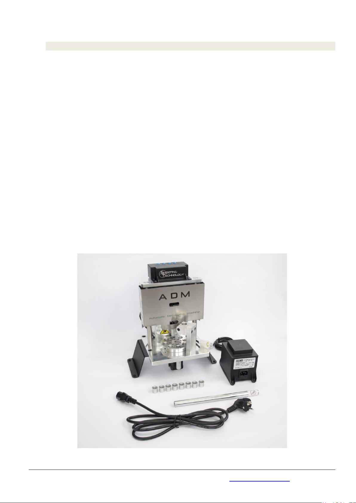
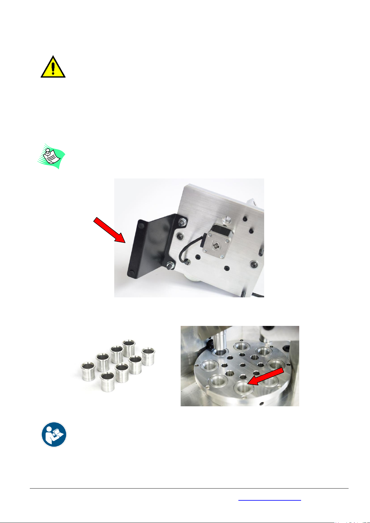
Togliere l’imballo che avvolge la macchina, assemblare i piedini regolabili o le lamiere di appoggio (dipende dal corredo
previsto) avvitarli alla base della macchina.
Remove the packaging protection, assemble the adjustable feet or the support plates on the base plate of
the machine.
Inserire le 8 boccole di centraggio bossolo nel tamburo
Insert the 8 case centering bushings in the drum
AVVERTENZA /
NOTE
:
per ogni caibro ci sono le relative boccole
there are the corresponding bushings for each caliber

Data 02/04/21
TECHNIQUE ENGINEERING di Arturo Busin & C snc P. I./ C.F./ Reg. Imp. 03122570249 REA 300945 (VI)
Via M. Corner 2/4 - 36016 - Thiene (VI) ITALY tel. +39 (0)445 576528 info@technique-engineering.it
Pag. 11 di 29
Fissare il tubo di alimentazione bossoli alla macchina con una chiave a brugola da 4mm, con la parte svasata rivolta
verso l’alto (entrata dei bossoli provenienti dal distributore)
Fix the feed pipe to the machine using a 4mm Allen wrench, with the flared side facing upwards (inlet cases from the
case feeder)
Attenzione: la parte terminale del tubo che comunica con il tamburo rotante deve essere circa 6 mm sopra il
colletto del bossolo (v.di figura)
Warning:
the feed pipe that communicates with the rotating drum, must be about 6 mm above the cartridge
case neck (see picture)
I bossoli vanno messi con la parte aperta verso l’alto. In caso contrario la macchina si ferma e si deve intervenire.
Casings should be placed with the open side facing upwards. If not, the machine stops and action must be taken
Collegare il cavo di alimentazione della macchina al trasformatore 1) e quello del trasformatore alla presa 2) e infine
collegare la spina alla presa di corrente 3) e premere interruttore su ON 4)
Connect the power cable of the machine to the transformer 1) connect the main wire to the transformator 2) and then the
transformator to power supply3) and push ON the switch power 4)

Data 02/04/21
TECHNIQUE ENGINEERING di Arturo Busin & C snc P. I./ C.F./ Reg. Imp. 03122570249 REA 300945 (VI)
Via M. Corner 2/4 - 36016 - Thiene (VI) ITALY tel. +39 (0)445 576528 info@technique-engineering.it
Pag. 12 di 29
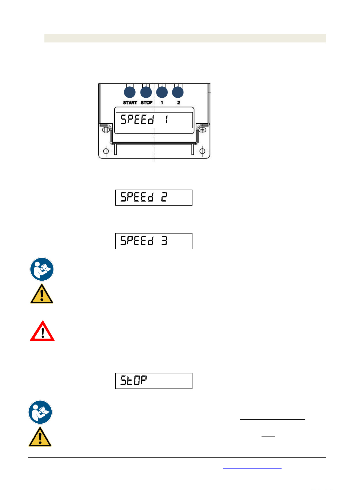
Il display presenterà per circa 5 secondi la seguente scritta:
for 5 seconds the display will be as follows:
Dopo i 5 secondi apparirà la scritta:
After 5 seconds the display will be as follows:
Premere il pulsante START, fare una prova a vuoto di funzionamento. La macchina deve funzionare senza rumori
anomali.
Press START button and make a no-load operation test. The machine must operate without noise.
Se tutto funziona, premere STOP. La macchina ADM ora è pronta per lavorare, basta completare il collegamento tra il
tubo alimentazione bossoli
If all is OK press STOP . The ADM machine is now ready for use, complete the connection of the case feed pipe with the
case feeder.
4DECRETO 22 gennaio 2008 - , n. 37 Regolamento concernente l'attuazione dell'articolo 11-quaterdecies, comma 13, lettera a) della legge n.
248 del 2 dicembre 2005, recante riordino delle disposizioni in materia di attività di installazione degli impianti all'interno degli edifici.
PERICOLO /DANGER
Il buon funzionamento dell’apparecchiatura ed il rispetto dei requisiti di sicurezza sono garantiti
soltanto se connessa ad impianto elettrico efficiente realizzato secondo le norme di legge
vigente (DLgs. 37/20084).
Il fabbricante non si assume alcuna responsabilità per qualsiasi danno all’apparecchiatura o a
terzi causato dall’utilizzo di un impianto non conforme alle norme vigenti.
The proper functioning of the equipment and compliance with the safety requirements are
guaranteed only when connected to the electrical system efficiently carried out according to the
rules of law in use (Legislative Decree 37/2008).
The manufacturer assumes no responsibility for any damage caused by using third party
equipment or if an installation does not comply with current standards.
1
2
3
4
Data 02/04/21
TECHNIQUE ENGINEERING di Arturo Busin & C snc P. I./ C.F./ Reg. Imp. 03122570249 REA 300945 (VI)
Via M. Corner 2/4 - 36016 - Thiene (VI) ITALY tel. +39 (0)445 576528 info@technique-engineering.it
Pag. 13 di 29
6ISTRUZIONI PER L’USO / USER INSTRUCTIONS
Dopo aver collegato la colonna di alimentazione bossoli ad un un distributore bossoli premere il pulsante START per
farla partire alla velocità 1 ( circa 2.000 bossoli / ora).
After connecting the feed pipe to a case feeder, press the
START
button to run the machine at speed 1 (approx. 2,000
cases per hour).
Per selezionare la velocità 2 premere il tasto START una seconda volta (circa 2.400 bossoli / ora)
To select speed 2, press the START button a second time (approx. 2,400 cartridge cases per hour).
Per selezionare la velocità 3 premere il tasto START una terza volta (circa 2.800 bossoli / ora)
To select speed 3, press the START button a third time (approx. 2,800 cartridge cases per hour).
AVVERTENZA –ATTENZIONE /
NOTE –CAUTION
In caso possano capitare bossoli molto sporchi o bossoli che possono avere la presenza di corpi estranei al loro
interno o bossoli che possono avere innesco tipo Berdan usare velocità massima 1
Per Utilizzo di bossoli carabina, utilizzare massima velocità 2
In case of presence of some very dirty cases or cases that may have foreign bodies inside them or cases that
may have Berdan primers site use maximum speed 1
For rifle cases use maximum speed 2
PERICOLO /
DANGER
Non inserire le mani sotto la macchina quando collegata alla corrente o durante il funzionamento.
Do not put hands under the machine when it is running or when it is connected to the electrical supply.
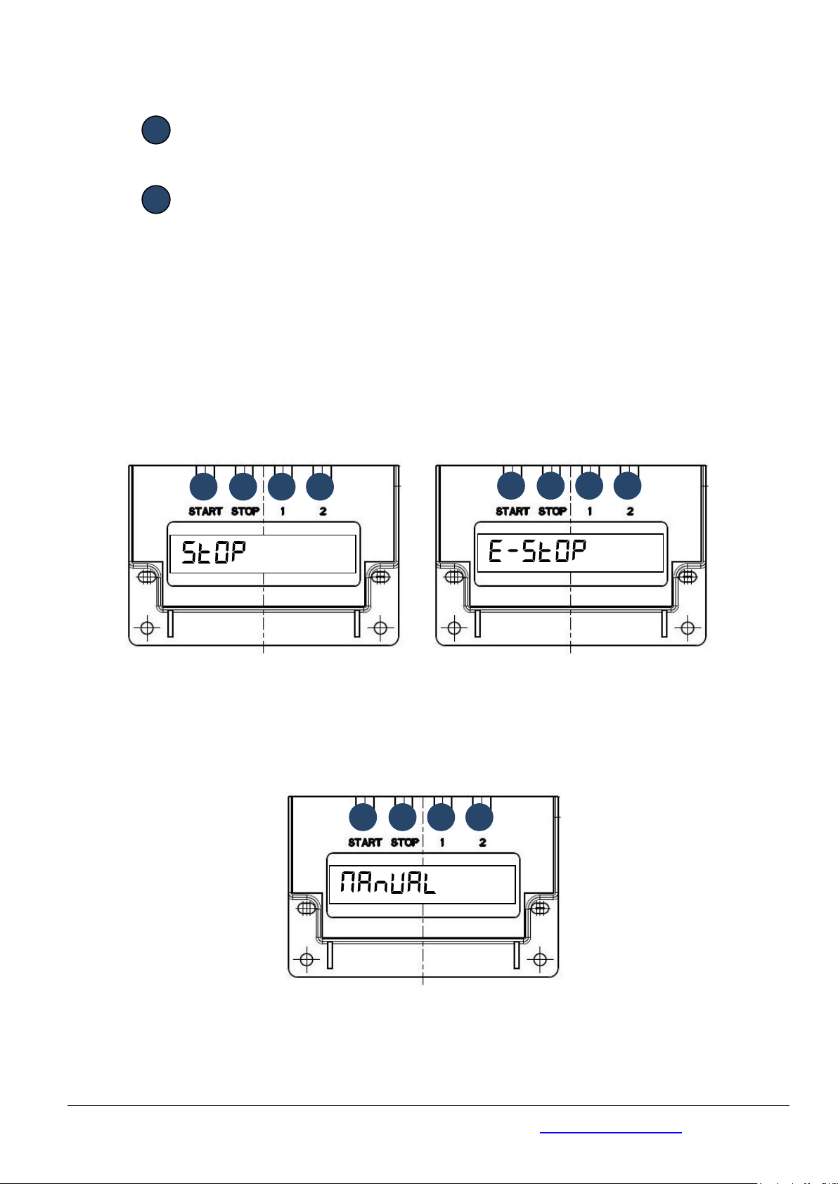
Per fermare la macchina premere il tasto STOP e sul DISPLAY comparirà la scritta:
To stop the machine press
STOP
button and the following message will appear on the display :
AVVERTENZA –ATTENZIONE /
NOTE –CAUTION
Dopo aver premuto lo il tasto STOP , per fare ripartire la macchina, si deve premere due volte il tasto
START perché la macchina deve riallineare i componenti.
After pressing the STOP button, to restart the machine, press the START button twice because the machine
must realign the components.
Data 02/04/21
TECHNIQUE ENGINEERING di Arturo Busin & C snc P. I./ C.F./ Reg. Imp. 03122570249 REA 300945 (VI)
Via M. Corner 2/4 - 36016 - Thiene (VI) ITALY tel. +39 (0)445 576528 info@technique-engineering.it
Pag. 14 di 29
6.1. FUNZIONE DEI TASTI /
CONTROL PUSH-BUTTONS PANEL FUNCTIONS
START
Serve per far partire la macchina e per selezionare le velocità
It is Used to start the machine and to select speeds
STOP
Serve per far fermare la macchina /It is used to Stop the machine
Il tasto STOP ha più funzioni:
Se premuto una volta la macchina si ferma con il punzone il posizione alta. Se non si dovesse fermare
in posizione alta premere, dopo lo STOP, il pulsante START e si posizionerà al punto morto superiore.
Se premuto consecutivamente 2 volte il punzone si arresta nella posizione che occupa in quel
momento. Usare lo stop di emergenza solamente in caso di anomalia. Per uscire dalla modalità E-STOP
premere una volta il tasto START
The STOP Button has further functions:
If it is
pressed once time
the machine stops with the punch in the high position. If it doesn’t stop in the
high position, press the START button (after the STOP) and it will be positioned at the top position.
If it is
pressed 2 times consecutively
the punch stops in the position it occupies at that moment
Tasto stop premuto una volta Tasto stop premuto 2 volte
STOP button pressed once time Stop Button pressed 2 times
Se tenuto premuto per 3 secondi si entra in modalità MANUAL, ovvero si può comandare il movimento
del punzone in posizione UP e DOWN con i tasti 1 e 2
If it is kept pressed for 3 seconds, you enter
MANUAL mode
, you can control the movement of the punch
in UP and DOWN positions with buttons 1 and 2
Data 02/04/21
TECHNIQUE ENGINEERING di Arturo Busin & C snc P. I./ C.F./ Reg. Imp. 03122570249 REA 300945 (VI)
Via M. Corner 2/4 - 36016 - Thiene (VI) ITALY tel. +39 (0)445 576528 info@technique-engineering.it
Pag. 15 di 29
1
Questo pulsante si utilizza solo in modalità manuale e muove solamente il punzone in posizione Up-
Down facendo girare il motoriduttore in senzo antiorario
Use this button only in manual mode. It moves the punch to the Up-Down positions , turning the gear
motor in counterclockwise rotation
2
Questo pulsante si utilizza solo in modalità manuale e muove solamente il punzone in posizione Down-
Up facendo girare il motoriduttore in senso orario
Use this button only in manual mode. It moves the punch to the Up-Down positions , turning the gear
motor in clockwise rotation
6.2. CAMBIO CALIBRO BOSSOLI /
CALIBER CHANGES
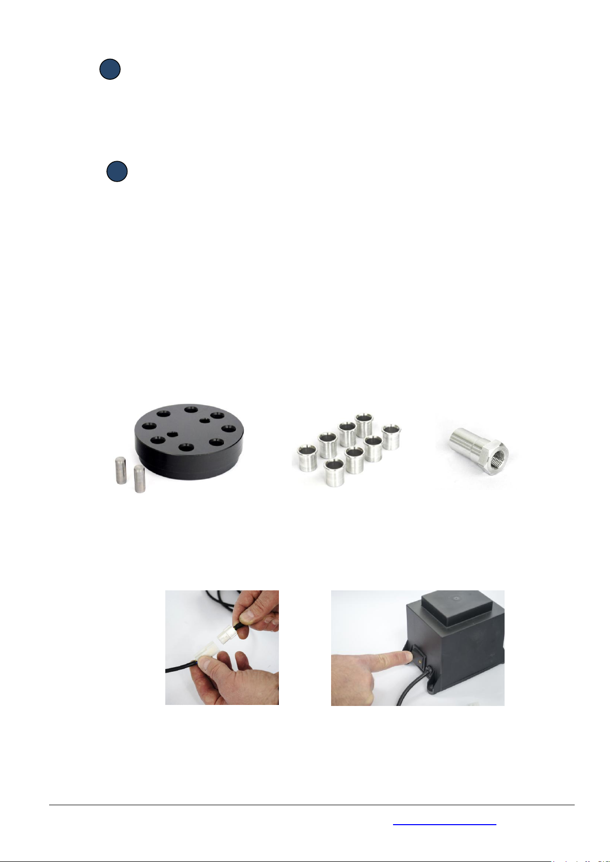
Quando si desidera cambiare calibro bossoli da decapsulare inserire nel tamburo le bussole corrispondenti al
calibro voluto, e verificare che il tubo di alimentazione e la protezione cilindrica siano idonei ai bossoli che si
vogliono utilizzare.
Per alcuni bossoli sarà necessario utilizzare il kit raffigurato nella figura sottostante
In order to decap different caliber cases, insert the corresponding bushings into the drum, and check that the
feed pipe is suitable for the new type of cases.
For some cases (revolver and rifle cases cartridges) it will be necessary to use the kit shown in the picture
below
Nel caso sia necessario il kit procedere come segue:
If the kit is required follow these instructions:
Spegnere la macchina rimuovendo il cavo di alimentazione o mettere interruttore su OFF
Turn off the machine by removing the power electric cable or move power switch to OFF
Data 02/04/21
TECHNIQUE ENGINEERING di Arturo Busin & C snc P. I./ C.F./ Reg. Imp. 03122570249 REA 300945 (VI)
Via M. Corner 2/4 - 36016 - Thiene (VI) ITALY tel. +39 (0)445 576528 info@technique-engineering.it
Pag. 16 di 29
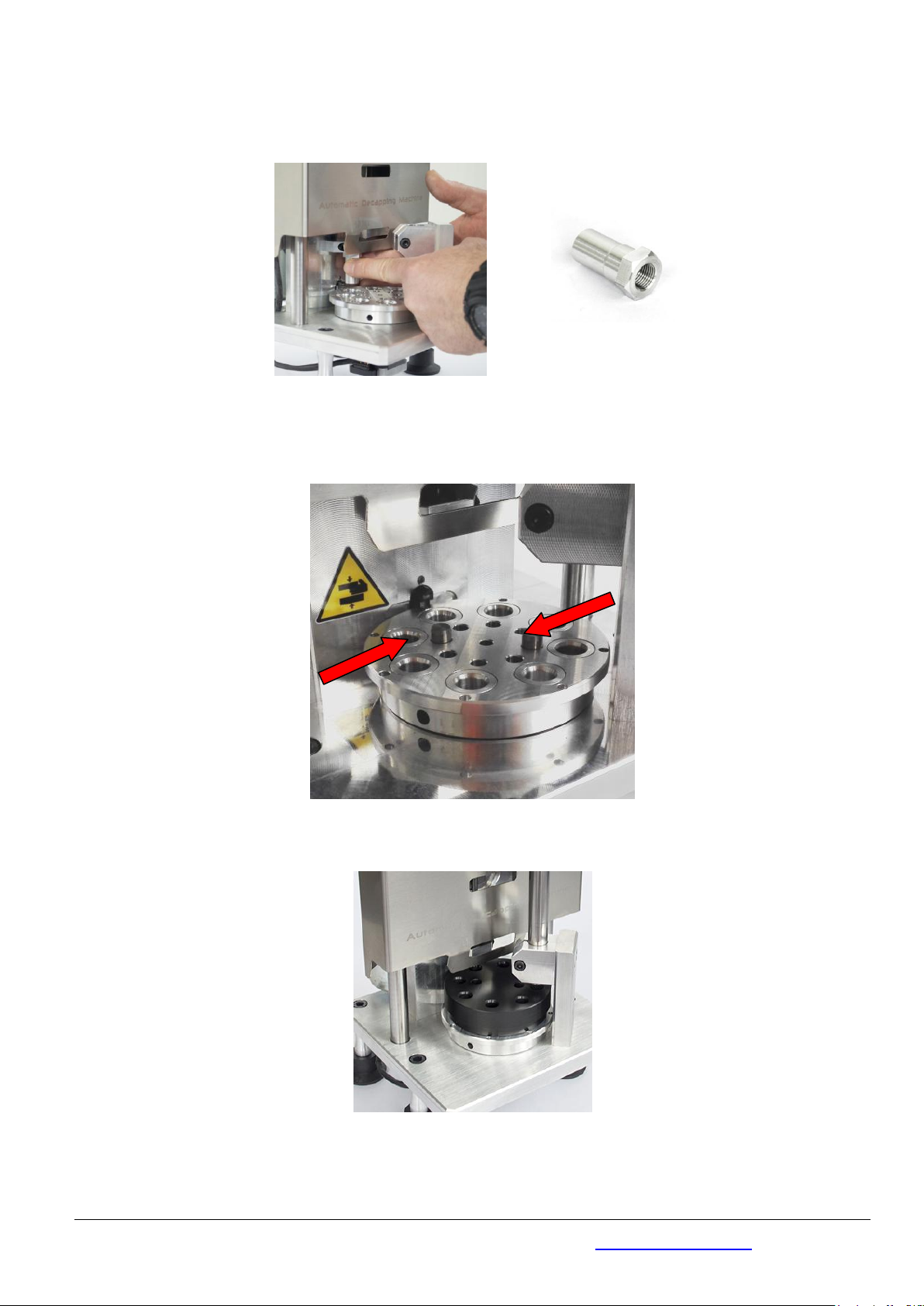
Rimuovere la protezione cilindrica in asse con il punzone svitandola
Unscrew and remove the cylindrical protection in line with the punch
inserire i perni di trascinamento sul tamburo bossoli (nei fori da 8 mm) e successivamente in corrispondenza
dei perni inserire il kit tamburo. Inserire anche le bussole di alluminio corrispondenti al kit
insert the drive pins on the case drum (in the 8 mm diameter holes) and then insert the plastic drum kit. Check
and insert the aluminum bushings corresponding the used kit
riposizionare il tubo alimentazione bossoli e avvitare la protezione cilindrica corrispondente al kit utilizzato
reposition the case feeder pipe as described in point 5.1, screw the corresponding kit cylindrical protection

Data 02/04/21
TECHNIQUE ENGINEERING di Arturo Busin & C snc P. I./ C.F./ Reg. Imp. 03122570249 REA 300945 (VI)
Via M. Corner 2/4 - 36016 - Thiene (VI) ITALY tel. +39 (0)445 576528 info@technique-engineering.it
Pag. 17 di 29
ESEGURE TUTTE LE OPERAZIONI CON MACCHINA SPENTA E CAVO DI ALIMENTAZIONE SCONNESSO
DALLA RETE. RIMONTARE TUTTE LE PROTEZIONI PRIMA DELL’UTILIZZO
CARRY OUT ALL THE OPERATIONS WITH THE MACHINE OFF AND THE ELECTRIC CABLE
DISCONNECTED. REASSEMBLE ALL PROTECTIONS BEFORE USE
Kit per bossoli / Cartridge cases kit:
-per calibro .40 SW -----------------> bussole relative e tubo alimentazione bossoli (diam. 16x2 mm)
-per calibro 45 ACP –HP ------------> bussole relative e tubo alimentazione bossoli (diam. 16x1,5 mm)
-per calibro 38/357M -------------> bussole del 40 SW, tubo per cal. 40SW, tamburo in plastica del
38/357 e protezione punzone del 38/357
-per calibro carab. 223 (5,56) -----> bussole del 9mm, tubo per cal. 9mm, tamburo in plastica del 223 e
protezione punzone del 223
-per calibro carab. 308 ------------> bussole del 45 ACP, tubo per cal. 45, tamburo in plastica del 308 e
protezione punzone del 308
-for caliber 40 SW ------------------> 40 SW bushings and feed pipe in 40 SW (diam. 16x2 mm)
-for caliber 45 ACP - HP-------------> 45 ACP - HP bushings and 45 ACP feed pipe (diam. 16x1,5 mm)
-for caliber 38/357 M --------------> 40 SW bushings, 40 SW feed pipe (diam. 16x2 mm), 223 plastic drum
and 38/357 punch protection
-for rifle caliber 223 -------------> 9mm bushings, 9mm feed pipe (diam. 16x2,5 mm), 223 plastic drum
and 223 punch protection
-for rifle. caliber 308 -------------> 45 ACP bushings, 45 ACP feed pipe (diam. 16x1,5mm), 308 plastic drum
and 308 punch protection
6.3. SOSTITUZIONE PUNZONE / DECAPPING PUNCH SOBSTITUTION
Può capitare che il perno punzone che decapsula i bossoli si possa spezzare o piegare. La macchina può
usare due tipi di aste punzoni : un’ asta decapsulatrice standard con perno montato ad interferenza e,
come accessorio un’asta composta scomponibile .
Si può sostituire il solo perno oppure l’intera astina, dipende se la rottura del perno è tale da poterla sfilare
dal di alloggiamento sull’astina (il perno è alloggiato per interferenza sull’asta).
Per rimuovere l’asta per entrambi i casi , procedere come segue:
It’s possible to brake or bend the decapping punch pin. The machine can use n.2 diferent version of rod. One is
the standard Rod with the pin fixed by interference, the second one as accessory is a Compound Rod. You can
substitute the complete decapping rod or only the decapping punch pin; it depends for the type of failure . In
order to remove the complete decapping rod and pins for both, follow the following steps:
Posizionare il punzone al punto morto superiore
Stop the machine with the decapping punch in top position
Spegnere la macchina rimuovendo il cavo di alimentazione
Turn off the ADM machine
Rimuovere la protezione cilindrica in asse con il punzone svitandola
Unscrew and remove the cylindrical protection
Data 02/04/21
TECHNIQUE ENGINEERING di Arturo Busin & C snc P. I./ C.F./ Reg. Imp. 03122570249 REA 300945 (VI)
Via M. Corner 2/4 - 36016 - Thiene (VI) ITALY tel. +39 (0)445 576528 info@technique-engineering.it
Pag. 18 di 29
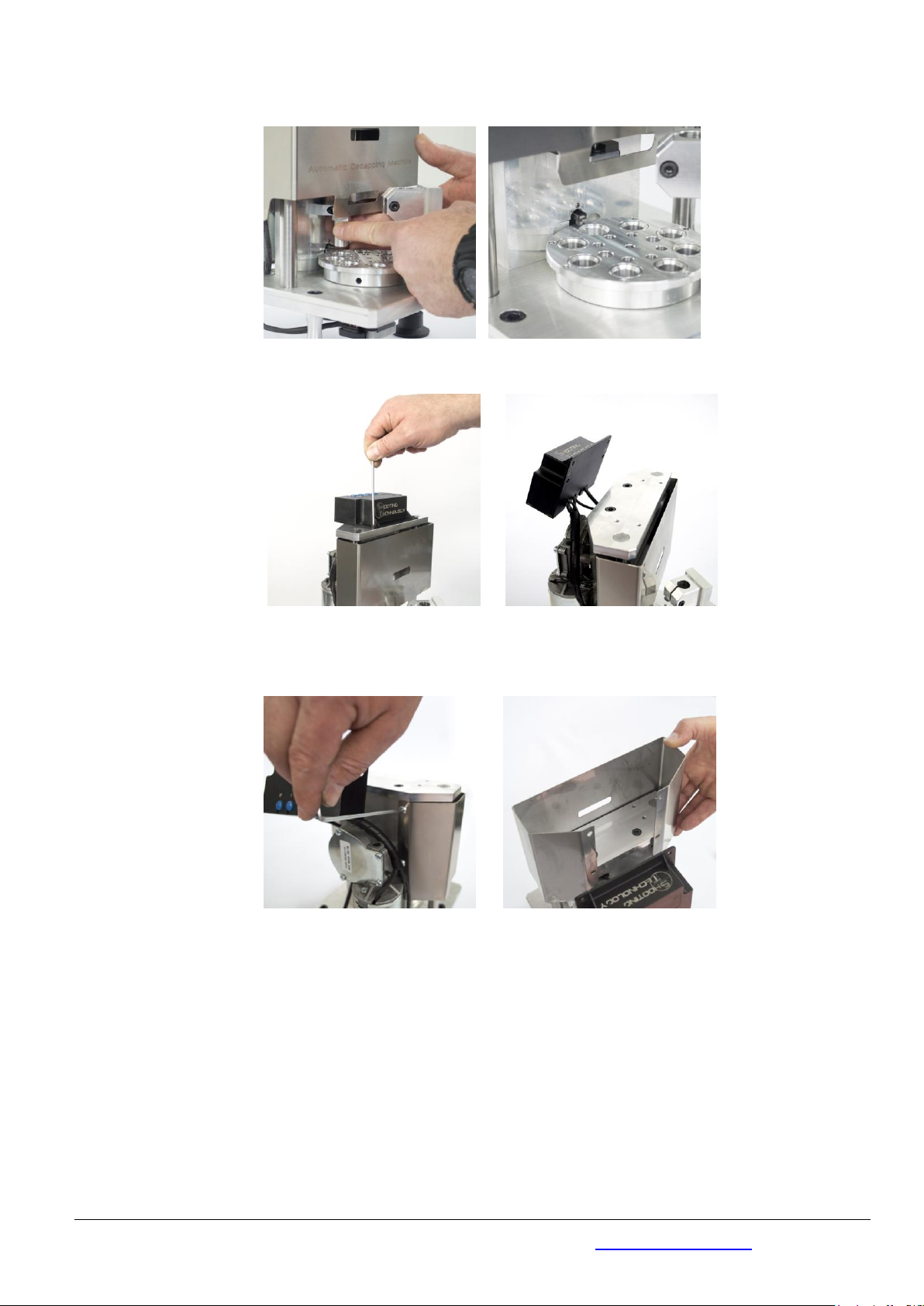
Rimuovere le 4 viti che fissano la scatola centralina e sollevarla come in figura
Remove the fixing control unit box screws , and lift as shown in the pictures
Svitare e rimuovere le 4 viti che fissano la protezione in lamiera e sfilarla dall’alto come in figura
Unscrew and remove the 4 fixing sheet metal protection screws and remove the protection from above, as
shown in the pictures

Data 02/04/21
TECHNIQUE ENGINEERING di Arturo Busin & C snc P. I./ C.F./ Reg. Imp. 03122570249 REA 300945 (VI)
Via M. Corner 2/4 - 36016 - Thiene (VI) ITALY tel. +39 (0)445 576528 info@technique-engineering.it
Pag. 19 di 29
a) VERSIONE ASTA PUNZONE STANDARD - DECAPPING STANDARD PUNC ( pin fixed by interference)
Svitare il grano filettato M5 che fissa l’astina, liberare l’astina e lasciarla sfilare attraverso il foro caduta
inneschi esausti come da procedura .
Unscrew the M5 decapping punch locknut, make free the decapping punch and slide out it through the
decapped primer exhaust hole.
In caso di difficoltà a sfilare l’astina aiutarsi con una pinza ed un
martelletto come in figura (senza rovinare la superficie dell’astina).
If you have a difficult to take away the decapping punch, help yourself
with a clamp tool and a little plastic hammer as shown .
Sostituire l’astina o solamente il perno punzone e rifare le operazioni in processo inverso per rimontare il
tutto. Per montare l’asta rispettare la posizione come indicato e fissare il grano filettato.
Replace the decapping punch or just the decapping pin and reassemble everything repeating the operations
in reverse order. To mount the rod , pay attention to its position as shown below and then fix it with the screw
Nel caso si sostituisca solamente il perno punzone, quest’ultimo è inserito nel suo foro di alloggiamento con
un accoppiamento forzato. Pertanto deve essere tolto aiutandosi con una morsa e pinza, poi rimettere
quello nuovo battendo delicatamente con un martelletto una volta inserito nel foro.
Data 02/04/21
TECHNIQUE ENGINEERING di Arturo Busin & C snc P. I./ C.F./ Reg. Imp. 03122570249 REA 300945 (VI)
Via M. Corner 2/4 - 36016 - Thiene (VI) ITALY tel. +39 (0)445 576528 info@technique-engineering.it
Pag. 20 di 29
If the only decapping pin is to be replaced, note that it is fitted in in its housing hole by friction.
In order to remove it help yourself with a bench vise and a clamp tool.
In order to assemble the decapping pin, insert it in the decapping punch hole and tap it gently with a hammer
Asta Decapsulatrice con perno decapsulatore standard montaggio ad interferenza / Standard Decapping
Rod with interference mounting
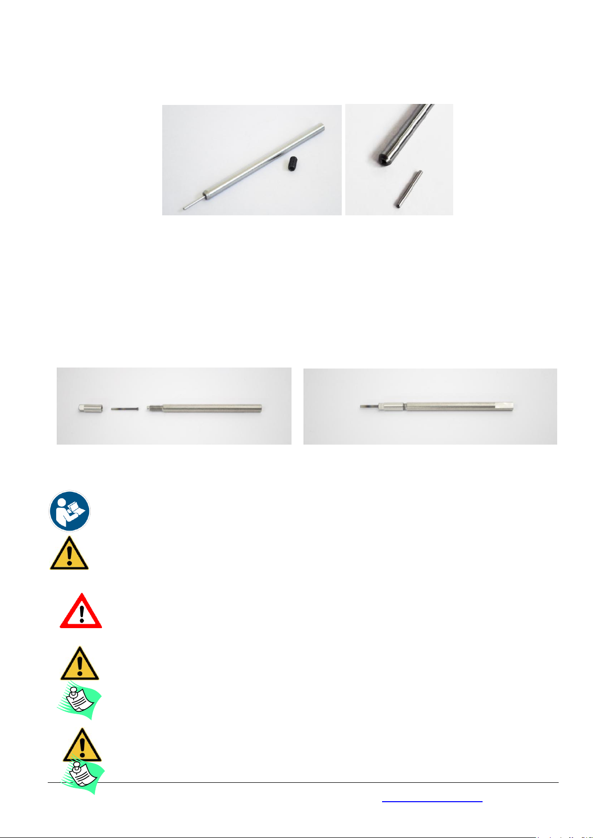
b) VERSIONE PUNZONE CON ASTA SCOMPONIBILE - COMPOUND DECAPPING ROD
In questo caso si puo’ sostituire il perno senza tolgiere l’asta.Esso inserito nel suo foro di alloggiamento
all’interno della testa punzone che si svita dall’asta . Puo’ essere tolto aiutandosi con una pinza. Una volta
sostituito avvitare bene la testa punzone all’asta.
In this case the pin can be replaced without removing the rod. It is inserted in its housing hole inside the
punch head which is unscrewed from the rod . It can be removed with the help of pliers. Once replaced, screw
the punch head onto the rod.
Asta Decapsulatrice con perno scomponbile smontata e assemblata / Compound Decapping Rod and its pin
disassembled and assembled
ATTENZIONE /
WARNING
Con la versione asta Compound, per decapsulare I bossoli da carabina calibro 308, l’astina deve essere
infilata nella sua sede ed alzata fino a battuta con la slitta di acciaio (ovvero deve essere alzata
ulteriormente)
If you use the Compound decapping rod for depriming the .308 cartridge cases, the decapping punch rod
must be raised up to the stop with the steel slide.
ESEGURE TUTTE LE OPERAZIONI CON MACCHINA SPENTA E CAVO DI ALIMENTAZIONE SCONNESSO DALLA
RETE. UTILIZZARE LA MACCHINA SEMPRE CON TUTTE LE PROTEZIONI CORRETTAMENTE MONTATE
CARRY OUT ALL THE OPERATIONS WITH THE MACHINE OFF AND THE ELECTRIC CABLE DISCONNECTED.
REASSEMBLE ALL PROTECTIONS BEFORE USE
SEGUIRE ATTENTAMENTE LE ISTRUZIONI DI MONTAGGIO DELL’ASTINA ALTRIMENTI PUO’ ANDARE IL COLLISIONE
COL FONDO DEL BOSSOLO E BLOCCARE LA MACCHINA
FOLLOW THE ASSEMBLY DECAPPING PUNCH INSTRUCTIONS CAREFULLY AS OTHERWISE IT MIGHT COLLIDE WITH
THE BOTTOM OF THE CASE AND BLOCK THE MACHINE
In caso di sostituzione del solo perno punzone attenzione a non improntare o rovinare la superficie
rettificata dell’astina durante l’operazione di rimozione del relativo perno
During the decapping pin removal operation do not damage the punch ground surface.
Table of contents
Popular Industrial Equipment manuals by other brands


SKC
SKC 225-69 operating instructions

Montanari
Montanari MGS19 Installation, use and maintenance

MVP
MVP HVDG-2000 Operation manual

Index
Index B500 Operating instructions and Maintenance instructions

Village
Village LW-160 User guide and reference manual

FRIEDHELM LOH
FRIEDHELM LOH Rittal SK 3363 Series Assembly and operating instructions