Shopline 2D Shop User manual
2D_Shop camera . English manual
1
2D_Shop
Camera for Video Analytics
Thomas Nenner
March 31, 2017
Release 2.5.6
USER MANUAL
The people counter 2D_Shop is an overhead sensor which analyzes infrared Images. This Process makes
the device light variations independent that might affects other devices counting accuracy. The advantages
from this technology are:
oBidirectional counting.
o–Accuracy over 95%.
o-No shadows Influence.
o-Good accuracy in low light conditions.
This sensor provides real time analytics locally and on the cloud

2D_Shop camera . English manual
2
Index
1. Site and hardware considerations........................................................................................................................3
Connections diagram................................................................................................................................................3
Coverage :.................................................................................................................................................................3
Standard model. ...................................................................................................................................................3
Installation ................................................................................................................................................................4
Orientation ...............................................................................................................................................................5
Electrical ...................................................................................................................................................................5
Cabling ......................................................................................................................................................................6
Pulse system compatibility.......................................................................................................................................6
IP address switch ......................................................................................................................................................7
2. Parameters-Settings .............................................................................................................................................8
Finding the camera:..................................................................................................................................................8
Device identification.................................................................................................................................................8
Network settings ....................................................................................................................................................10
Time settings ..........................................................................................................................................................11
Channels .................................................................................................................................................................11
Data delivery...........................................................................................................................................................12
Source .....................................................................................................................................................................13
Validation............................................................................................................................................................14
Heat map ............................................................................................................................................................14
Status, and sytem ...................................................................................................................................................16
3. Local Server Configuration .................................................................................................................................17
Technical.................................................................................................................................................................19
Local PC IP address .............................................................................................................................................19
FTP program .......................................................................................................................................................19
Directories ..............................................................................................................................................................19
4. Real time analytics..............................................................................................................................................20
Documentation.......................................................................................................................................................21

2D_Shop camera . English manual
3
1.Site and hardware considerations
Connections diagram
The camera sends the data on Ethernet on a server:
1.
Figure 1 Connection diagram
Coverage :
It depends on the ceiling height and on the optical parameters.
Two models are available :
Standard model for ceilings up to 3.2 meter,
High sensitivity for ceilings up to 4.5 m
Standard model.
It is based on a 3.6 mm lens
Ceiling
height
Coverage
2.2 m
1.9 m
2.4 m
2.1 m
2.6 m
2.3 m
2.8 m
2.4 m
3.0 m
2.5 m
3.2 m
2.6 m
Figure 2 Coverage for the standard model
RJ45
RJ45
POE
Injector
2D-Shop
Power
Supply
Internet
Server

2D_Shop camera . English manual
4
High sensitivity
Ceiling
height
Coverage
2.5 m
2.6 m
3.0 m
3.1 m
3.5 m
3.7 m
4.0 m
4.1 m
4.5 m
3.5 m
Figure 3 coverage for the high sensitivity model
Installation
The camera is attached under the ceiling with the omega shaped bracket and a pair of expansion bolts.
Figure 4 back of the camera
Attach the bracket first with a pair of expansion bolts
Then introduce the camera and fasten the 8 mm hex bolt with a 10 mm wrench.
Turn the camera so that it looks parallel to the entrance.
2D_Shop camera . English manual
5
Orientation
The 3 leds must be inside the shop, in order to have a simple default software installation
Inside
Figure 5 : orientation of the camera
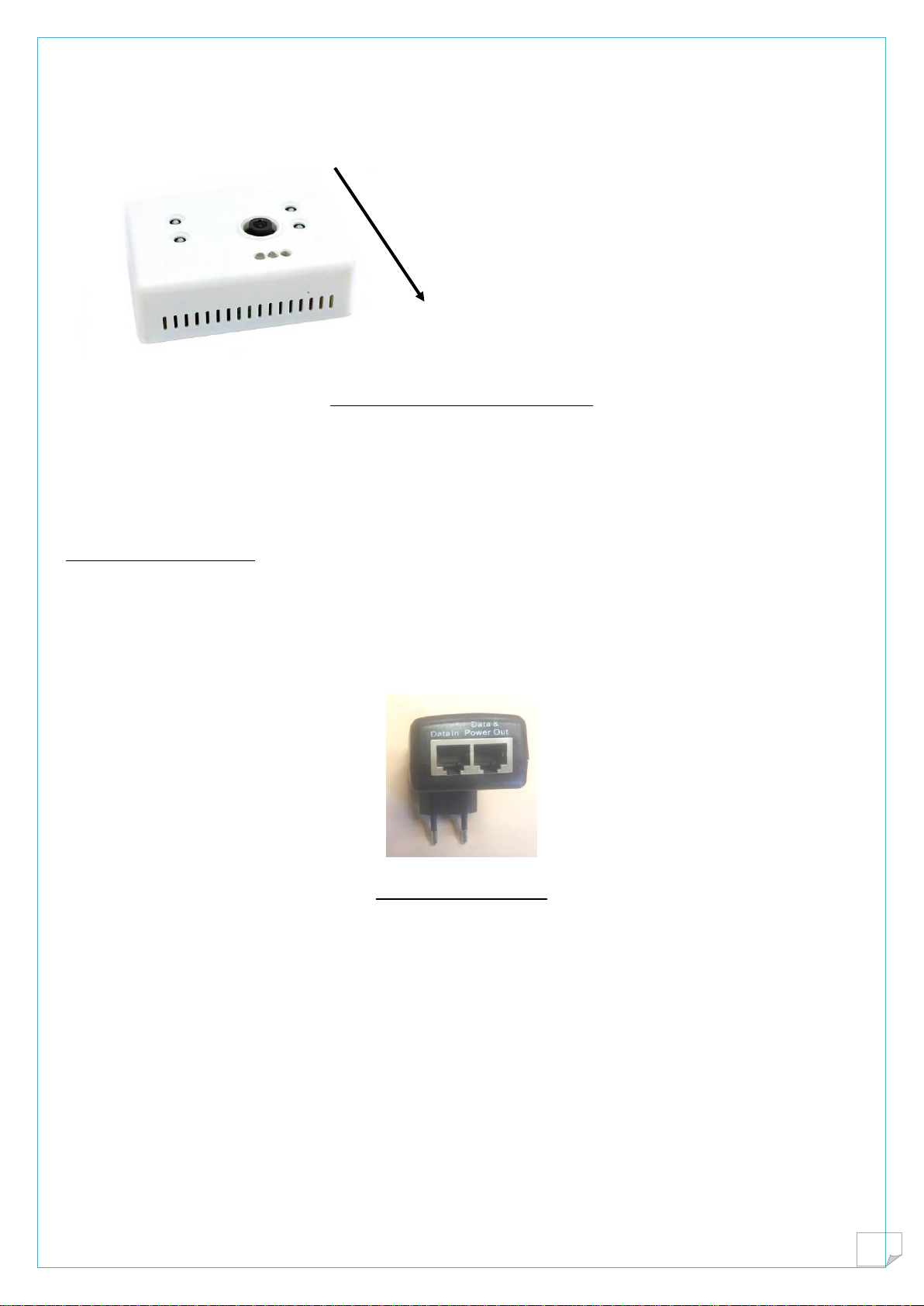
Electrical
On the back of the camera are two connectors :
RJ45 connector : it is a POE link, the network cable carries the power and the Ethernet data.
Green pulse connector : useful when the camera is for infra red beam replacement.
POE Ethernet connection
This camera uses passive POE (power over Ethernet) connector.
The cable carries 0 Volt on pins 7,8, and +48 Volts on pins 4,5
Connecting the camera to an active POE switch will not work.
A POE power supply is provided with the camera :
Figure 6 : POE adapter
Data in goes to the IT switch
Data and power out connect to the camera
In case of multiple cameras, a poe switch is desirable.
It must be the passive type with power on 4,5 and 7,8 .

2D_Shop camera . English manual
6
Figure 7 : POEswitch passive
When booting up, a multicolor led blinks on the camera, and after boot up it will extinguish.
Cabling
This a reminder only.
Cat 5 or Cat6 Ethernet cable is necessary, with proper A or B cabling as shown in the next figure.
Telephone cable will not work properly even on short distances.
Figure 8 normalized cabling A or B
Pulse system compatibility
It happens that on some site no Ethernet cable is available.
Ethernet connector is used for initial tuning.
The green connector carries 4 signals
Ground , 0V
Positive voltage

2D_Shop camera . English manual
7
Entrances
Exits
A 15 Volts, 2A power supply is necessary. (a 12 V 1A power supply will NOT work)
When detecting the camera will produce a 15 V pulse which can be fed in a dat logger as usual.
IP address switch
Figure 9 switch and led position
By depressing the IP address switch with a paper clip during 3 seconds, the camera goes back to default
address 192.168.1.7.
IP adres reset switch
Flashing led at boot up

2D_Shop camera . English manual
8
2. Parameters-Settings
Finding the camera:
The camera is a network device, and all necessary settings are done through a browser, for example
internet explorer. We recommend that installer carries a laptop and a switch.
New camera
Default address of new cameras is 192.168.1.7
In order to communicate, set the laptop address to a compatible network : for example 192.168.1.xx
Connect camera to the PC , if necessary use a switch.
On the browser, type 192.168.1.7 then the camera menu must appear.
Already programmed camera
Normally the address is written on the device, and one must repeat the above operation, being sure that
the pc is in compatible address.
Suppose the 3d was in 199.188.177.166
We must set our laptop to 199.188.177.xx to be able to communicate.
Unknown address
The Cbox finder program is available to find all devices in the network.
It is available on our website : upgrade.shopline.fr
http://upgrade.shopline.fr/Utilitaires/cbox_finder.exe
Figure 10 : list of devices in the network
It will show you the list of connected devices to the local network.
Choose your device and press connect to see the device in default browser.
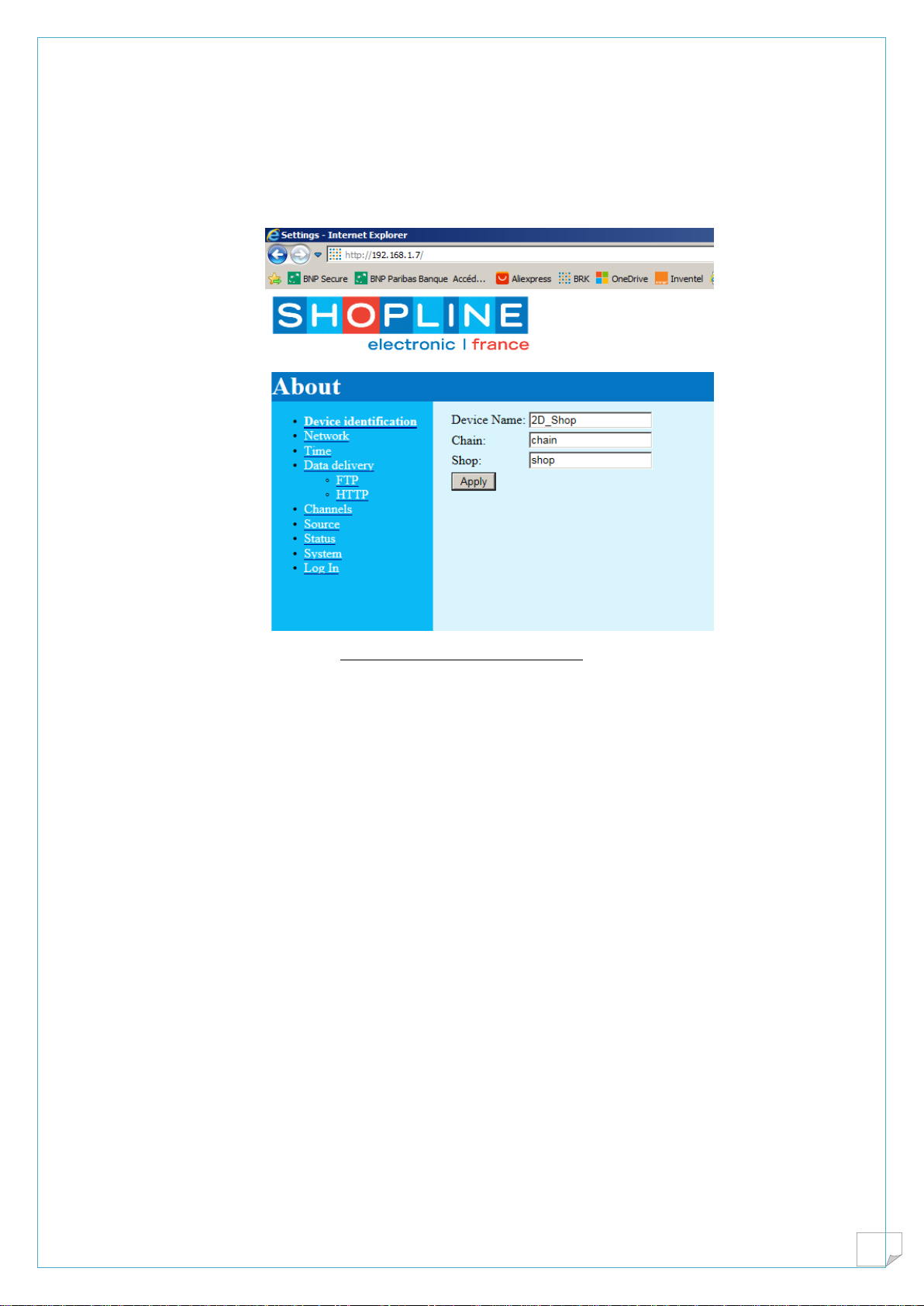
Device identification
This identification is useful in multiple camera use, it has no influence on file generation.
2D_Shop camera . English manual
9
Remember that hierarchy in people counting in shops is :
Chain of stores Mychain
Shop Paris
Door Entrance
Figure 11: Device identification
2D_Shop camera . English manual
10
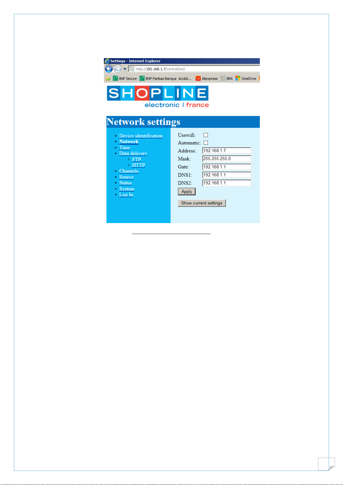
Network settings
Figure 12 : Network settings
Device is delivered at address 192.168.1.7
DNS is set into the router which will work most of the time, if needed introduce another DNS address.
This is quite important as the camera must find the time server on the internet to update internal clock;
Automatic work or DHCP will set automatically parameters, they can be seen by “show current settings”
2D_Shop camera . English manual
11
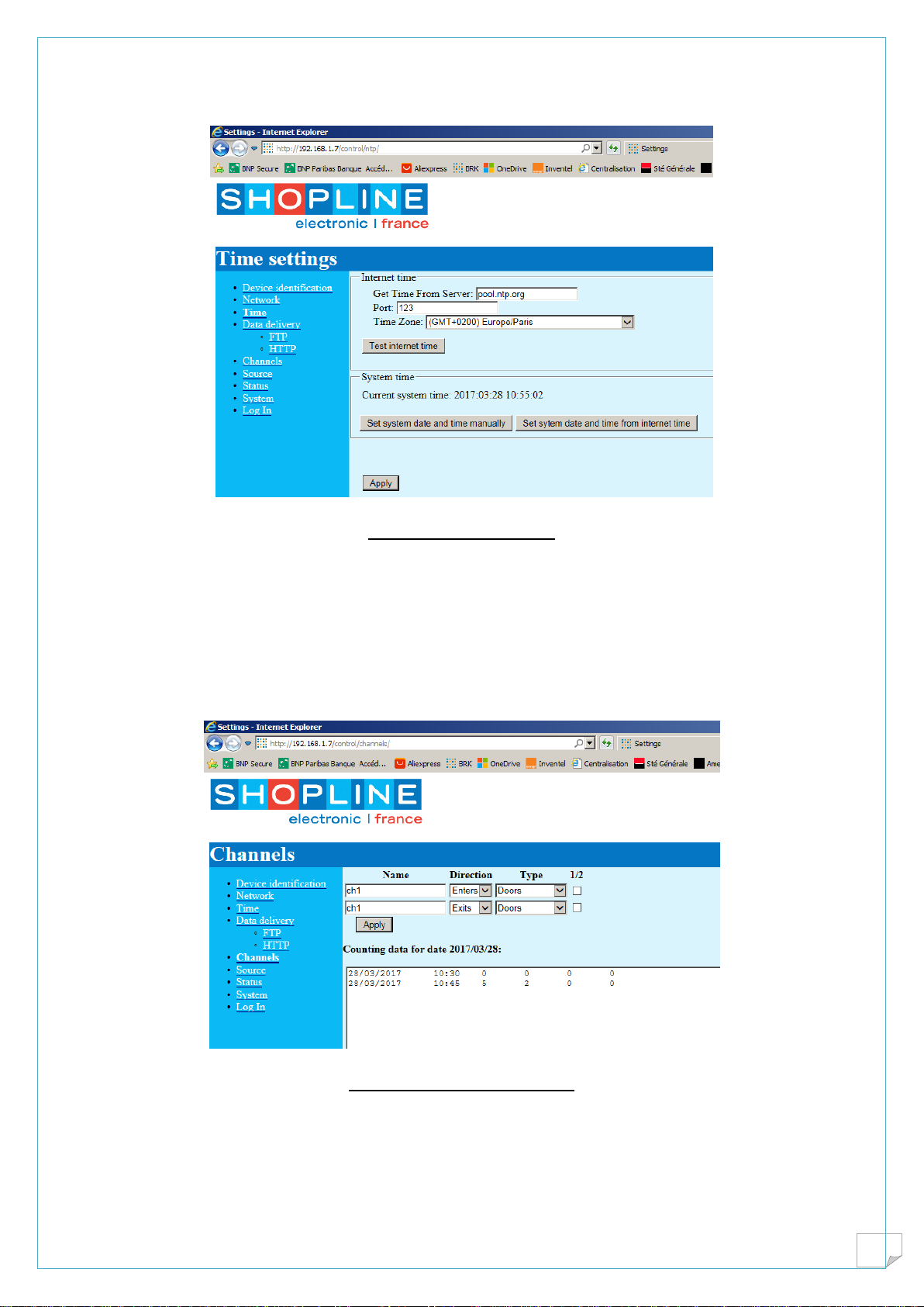
Time settings
Figure 13: Time settings
Check that this is running fine, because we need the date and time for file generation.
We may run on internal clock, but as it may drift one should update time from time to time.
Remember that it needs the DNS
Channels
Figure 14 : Channel definition
These features will be included into the file produced.
Name Is the name of the door, should be the same on line 1 and line 2
Direction As shown enters on line 1 and exits on line 2 will give correct results if the camera is
oriented with leds toward the inside of the shop.
2D_Shop camera . English manual
12
Type Most of the time the type of counting will be entrance to the shop. It can be set as corridor as well,
especially if heatmap is used only.
½ division In some cases, quite rare, accuracy will be improved if both channels are used as entrances
added and the total divided by two.
The window shows the number of counts per 15 minuts agregation time. It cannot be changed.
The last two channels are kept for software compatibility with data logger CBOX used with infra red
beams.
At the bottom, arrows show recorded data into device memory for approximately one month.
In some cases a paste and copy can be usefull.
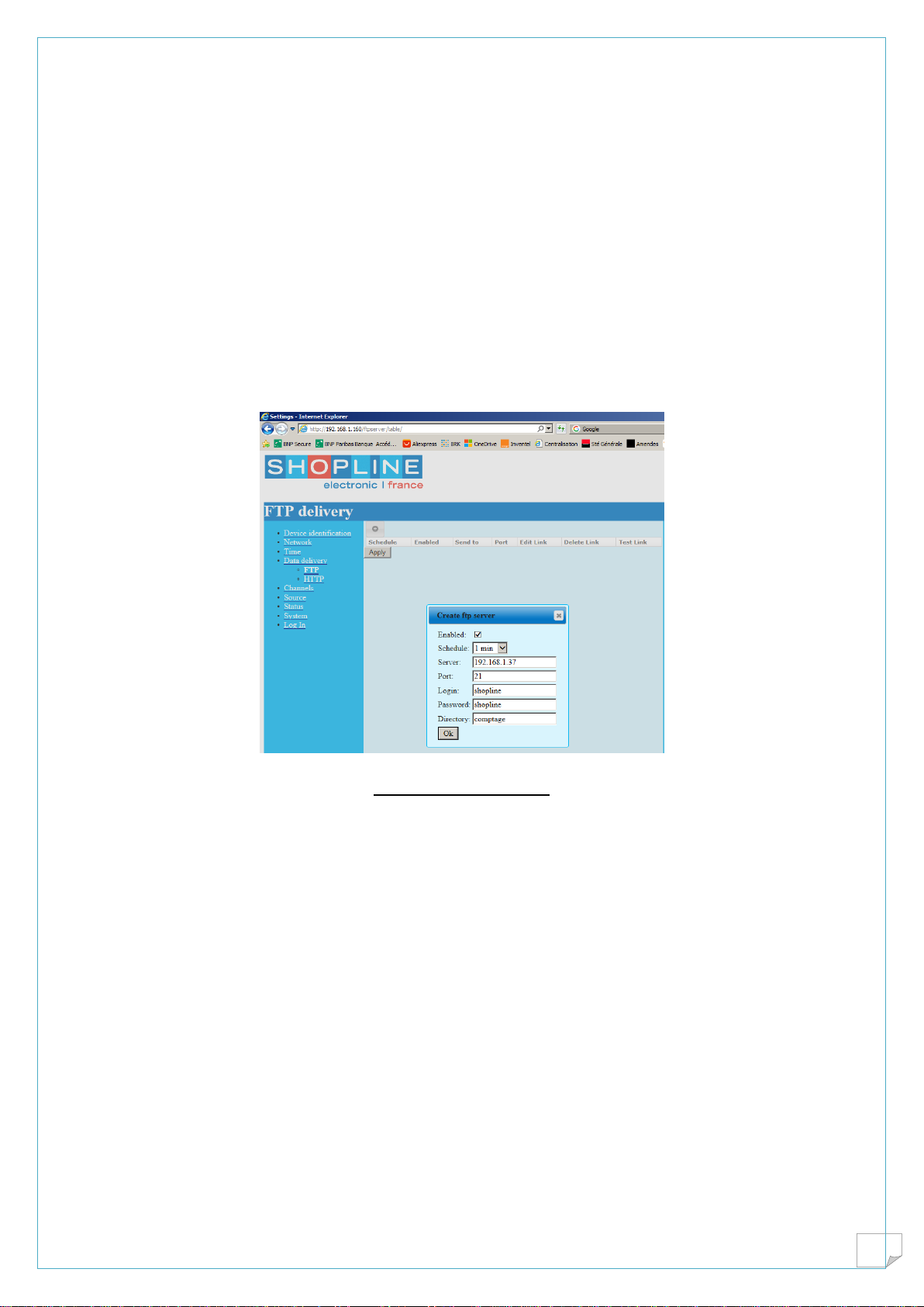
Data delivery
Figure 15 Data delivery
Data can be delivered to some FTP or HTTP server.
Many instances can be installed by the “ADD” button for example to send to local PC and some server.
Most common is the FTP protocol, which needs opening port 21 on the route. It will be described in the
software section.
Delivery schedule From once a minut to once a day. In case of a multiple store server be
carefull not to overload the link and the data base service.
IP address of the server It can be on the local server as seen on the figure, 192.168.1.37 or on a
distant server like frequence.shopline.fr
Login Name of the FTP account
Password Name of the password for this account
Directory A directory is created automatically on the server account directory.
The settings which are indicated in the figure will be convenient when configuring a server on a local PC
in a shop.
Testing Will ensure that everything is fine and that the file will be safely written on
the server
2D_Shop camera . English manual
13
File generated
Files are generated according to proprietary SCB format, aggregation will be 1 file per day as “date.scb”
They are plain text files which can be opened with any editor, like notepad.
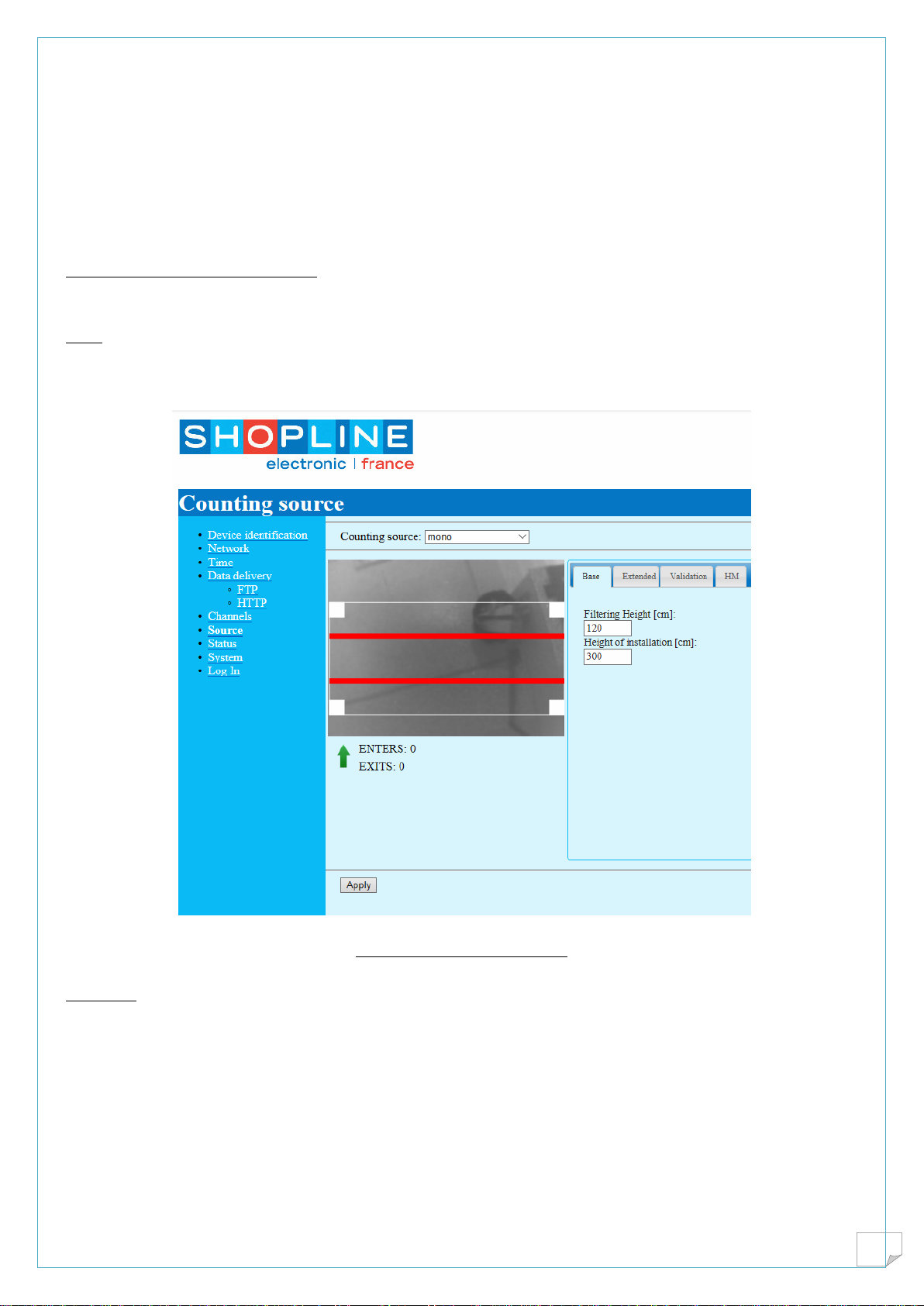
Source
This sreen shows the image seen by the camera, as well as the region of interest and 2 counting lines.
Underneath one can see the counting results , the arrow shows the direction of entrance, remember that
the 3 leds must be inside the shop.
Base
It shows ceiling height and filtering height. This feature is not implemented on the 2D counter, it is
indicative for the user.
Figure 6 : Base source menu
Extended
This allow you to tune the 2D_Shop versus height and sensitivity
Minimum area filtering of small objects, default is 20
Iso between 1 and 100 % must be set to have a light grey image
Apply sensitivity 1,2,3 filtering dark pixels
Change the value and validate the input will cause the device to take the new value into account
Make the setting permanent with validation at bottom of the screen

2D_Shop camera . English manual
14
Figure 6 Extended menu for gain settings
Validation
This will send to a FTP server the recording of the image and the counts. One must realize that the volume
can be high and overload the server.
Heat map

2D_Shop camera . English manual
15
The heat map can be seen on the navigator screen and sent to a server for recording and further
treatments. Note the zoom on the left image.

2D_Shop camera . English manual
16
Status, and sytem
These pages shows detailed information’s for debug and trouble shooting.
In order to save the entire device configuration you must save changes pressing apply new settings

2D_Shop camera . English manual
17
3. Local Server Configuration
A classical way to obtain transformation rate is to mix on the local PC footfall and sales figures. The
consequence is that this local PC must be turned into a FTP server. An installer called single camera setup
is provided which will setup the popular Filezila server using default analytic directories, and main video
alnalytic programs.
http://upgrade.shopline.fr/Distribution%20FR/singlecam_setup.exe
For simplicity click only on the real time part of the analytic, RPOS program
If necessary use one of the popular POS software editor

2D_Shop camera . English manual
18
Some technical informations….
Installation of the FTP server
Check the account and correct :
Login shopline
Password shopline
Main directory shopline with all the rights

2D_Shop camera . English manual
19
Technical
Channel 21
A window PC is protected by the firewall . You must allow the data traffic on FTP by opening channel 21
on local pc.
GOTO control panel, firewall, advanced , incoming rule, new rule, port , protocol TCP, local port 21, call
it FTP.
Check the antivirus for the same
Local PC IP address
The local pc must have a fixed address in same domain as the camera. If the pc is in automatic mode, it
must be changed to fixed address.. In this example it is 192.168.1.37
FTP program
Sometime you must give clearance to FTP program itself
Now you can test the ftp data delivery on the camera
Directories
On the camera we remember :
PC address is for example 192.168.1.37
Account name is shopline
Password shopline
Directory comptage
File name date.scb
Result is C:\shopline\comptage\date.scb
Data are ready for analytics !
2D_Shop camera . English manual
20
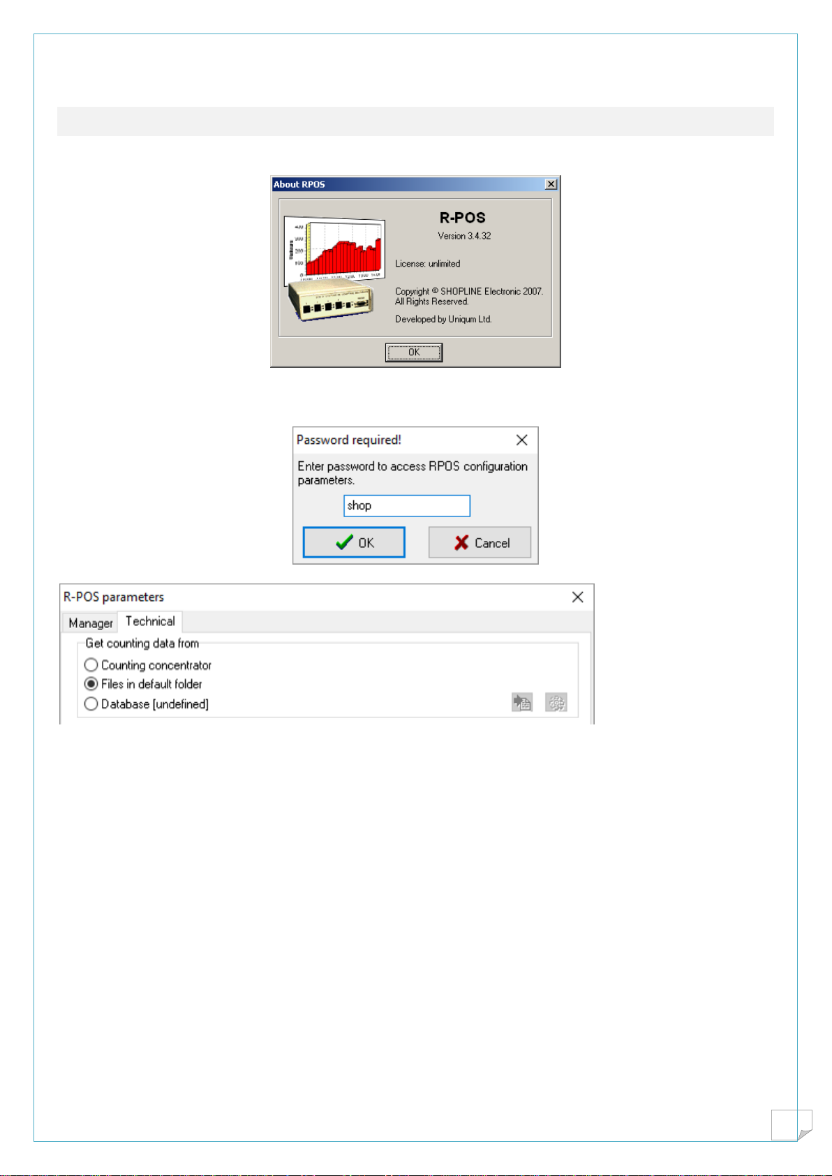
4. Real time analytics
After installation, an icon appears called RPOS
Goto parameters type the password shop
Set RPOS to files in default folder
You are ready to enjoy real time analytics
Table of contents


