ShoreStation ShoreScreen CS270-102-7B User manual


Document Number: 0004593
Rev: 1 Page 2
Introduction
The ShoreScreen Power Curtain system is designed to be assembled to a boathouse structure. The assembly process involves leg
bolts and mounting brackets to the boathouse, hanging the curtain sides, attaching the corner components, and pairing the wireless
remotes with the controller.
The assembly process explained in this document should be performed by a qualified ShoreStation technician who understands the
proper techniques and applications of the equipment used during the assembly process.
Safety Definitions
Safety messages are presented throughout this document and labels affixed to the product. The messages alert you to potential
hazards to you and/or property. The signal words DANGER, WARNING, and CAUTION are preceded by an alert symbol and
communicate the severity of potential hazard. The severity of each type of message is defined as follows:
DANGER indicates a hazardous situation which, if not avoided, will result in death or serious injury.
WARNING indicates a hazardous situation which, if not avoided, could result in death or serious injury.
CAUTION, used with the safety alert symbol, indicates a hazardous situation which, if not avoided, could result in minor or moderate
injury.
WARNING
DO NOT ATTEMPT TO ASSEMBLE THIS SYSTEM WITHOUT FIRST STUDYING THIS MANUAL AND
INFORMATION ON LABELS INCLUDED WITH THE SYSTEM. FAILURE TO DO SO CAN LEAD TO IMPROPER
OPERATION RESULTING IN SERIOUS PERSONAL INJURY AND/OR PRODUCT DAMAGE. IF YOU HAVE
FURTHER QUESTIONS AFTER REVIEWING THIS INFORMATION, CONTACT A SHORESTATION
REPRESENTATIVE AT (800) 859-3028.

Document Number: 0004593
Rev: 1 Page 3
Table of Contents
Click on the section title to jump to the section:
Introduction ......................................................................................................... 2
Safety Definitions................................................................................................. 2
Safety Instructions ............................................................................................... 3
Preparation .......................................................................................................... 4
Curtain Assembly Instructions ............................................................................. 4
Pairing the ShoreScreen Wireless Controls with your Boat Lift......................... 14
Pairing Existing FlexPower Controls................................................................... 15
Troubleshooting................................................................................................. 17
Safety Instructions
WARNING
Never install or work on the equipment without first verifying that the A/C power supply (if present) is protected by a functioning
Ground Fault Circuit Interrupt (GFCI) in accordance with National Electric Code section 210.8 and any additional local code requirements.
Disconnect all A/C power from the dock before installing or working on the equipment.
Assembly and installation of this system my require working over water. Always wear a personal floatation device (PFD) when working
over the water.
Remove any metallic objects from your person before working with DC or AC electrical components.
Always wear proper personal protective equipment such as safety glasses, gloves, hardhats, and clothing.
Never work alone and observe safe lifting practices such as team lifting and proper lifting posture.
Never pair the remotes to operate more than one boat lift. Doing so could cause unintended operation and result in injury and product
damage.
The system should only be run if the operator has clear vision of the lift equipment and its surrounding location.
Do not modify the equipment unless you have received direct written approval from the manufacturer (ShoreStation).

Document Number: 0004593
Rev: 1 Page 4
Preparation
Assembling the curtain takes at least two people and will require lifting and attaching components to the boathouse, but should not
affect the integrity of the structure.
Tools Required:
SAE and Metric Hex Keys (Allen Wrenches)
SAE Sockets and Wrenches
Cordless Power Drill
5/16 Power Nut driver
#3 Square drive
Curtain Assembly Instructions
1 –Organize Parts
Unroll the curtains, open the hardware box and bag, and sort the hardware and other contents by size.
2 –Attach the Brackets
All boathouses are different so the best bracket method depends on the boathouse. 1- bolt the clamp brackets
to the inside of the frame. 2- bolt the clamp brackets to the pile mounts. 3- bolt the clamp bracket to
crossbeams. Evenly space the clamps on both sides of the boathouse and open the clamps if they aren’t
already open. (Lag bolts are not included)

Document Number: 0004593
Rev: 1 Page 5
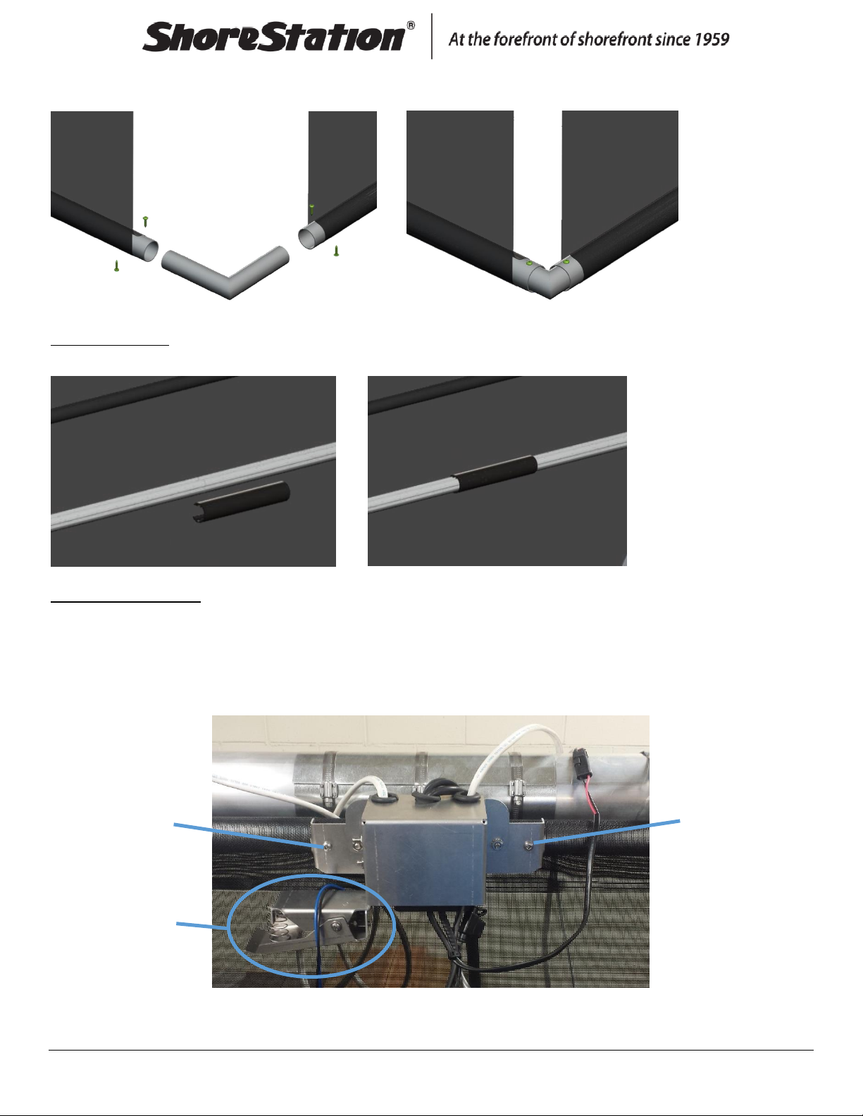
3 –Connect Tube Splices
Use a #3 square bit to drill the self-tap screws through the side tubes and splice as shown. There is a bundle of
side tubes and a bundle of end tubes, be sure to use the side tubes.
4 –Slide Tubes into Curtain
Slide the connected side tubes into the top of the side curtain and the end tubes into the top of the end
curtains as shown.
5 –Hang the Side Curtains
Start on the ends and put the top curtain tubes in the curtain clamps, and push the pin through the clamps to
secure the curtain. Then, repeat with all other clamps.
Long tubes
Tube splice

Document Number: 0004593
Rev: 1 Page 6
Make sure the plastic keder strip is facing up and is toward the outside of the boathouse as shown below.
6 –Slide Tubes into Curtain
Slide the connected side tubes into the bottom of the side curtain and the end tubes into the bottom of the
end curtains as shown.
7 –Connect Splice to Roll Tube
Use the 1-1/4” machine screws to join one side roll tube with one roll tube splice as shown. 24’ and 26’
curtains have one splice on each side and the 28’ curtain and bigger has 2 splices on each side.
Outside of boathouse
Keder strip
Inside of boathouse
Curtain
Roll Tube Splice
Roll Tube

Document Number: 0004593
Rev: 1 Page 7
8 –Slide on the Roll Tubes
Slide the side roll tubes onto the keder strip on the side curtains.
9 –Connect the Roll Tubes
Use the 1-1/4” machine screws to join the side roll tubes as shown.
10 –Connect the End Curtains to the Side Curtains
Slide the corner splices into the top on both sides of the end curtain tubes.
Corner splice

Document Number: 0004593
Rev: 1 Page 8
Then, slide the top corner splices into the side curtain top tubes. You may have to pull out the pin and pull
down on the side curtain tube as you insert the corner splice. (Push pin back into curtain clamp)
11 –Slide on the Roll Tubes
Slide the roll tubes onto the keder strip on the end curtains.
12 –Install the Corner Drives
Insert the side drive shaft into the bushing and line up the holes. Then slide the drive shaft and bushing into
the side curtain roll tube, line up the holes again, insert the 1-1/4” machines screws, and tighten. Also, slide
the end drive shaft into the end curtain roll tube, line up the holes, insert the screws, and tighten (as shown
below). Do the same on the opposite corner.
Side
curtain
End
curtain
Bushing
Side drive shaft

Document Number: 0004593
Rev: 1 Page 9
13 –Install Idler Corners
Slide the idler corner shafts into the roll tubes of the side curtain and end curtain. Line up the holes, insert the
1-1/4” machine screws, and tighten (as shown). Do the same on the opposite corner.
14 –Self-tap the Corner Splices
Adjust the top corner splices and curtain as needed and self-tap the screws through the curtain as shown. Tap
the screws closest to the corner first, then the screws through the curtain.
End
curtain
Side
curtain
Corner Drive
Corner Drive
Idler Corner
Idler Corner
Top View of ShoreScreen
Document Number: 0004593
Rev: 1 Page 10
Slide the corner splice into the lower tube of the side curtain and end curtain on all corners. Adjust as needed,
match the corner above, and self-tap the screws through the curtain as shown.
15 –Splice Cover
Snap on the plastic splice cover to the roll tube.
16 –Relay Placement
Place the relay assembly on the curtain tube, about half way down the curtain on the power side of the
boathouse, and use the self-tap screws to secure it to the top side tube. The relay assembly may have to be
adjusted depending on length of harness needed to reach the motors.
The upper limit switch automatically stops the curtain from rolling too high and into the relay assembly box. If
necessary it may be adjusted to prevent damage.
Self-tap screw
Self-tap screw
Upper Limit
Switch

Document Number: 0004593
Rev: 1 Page 12
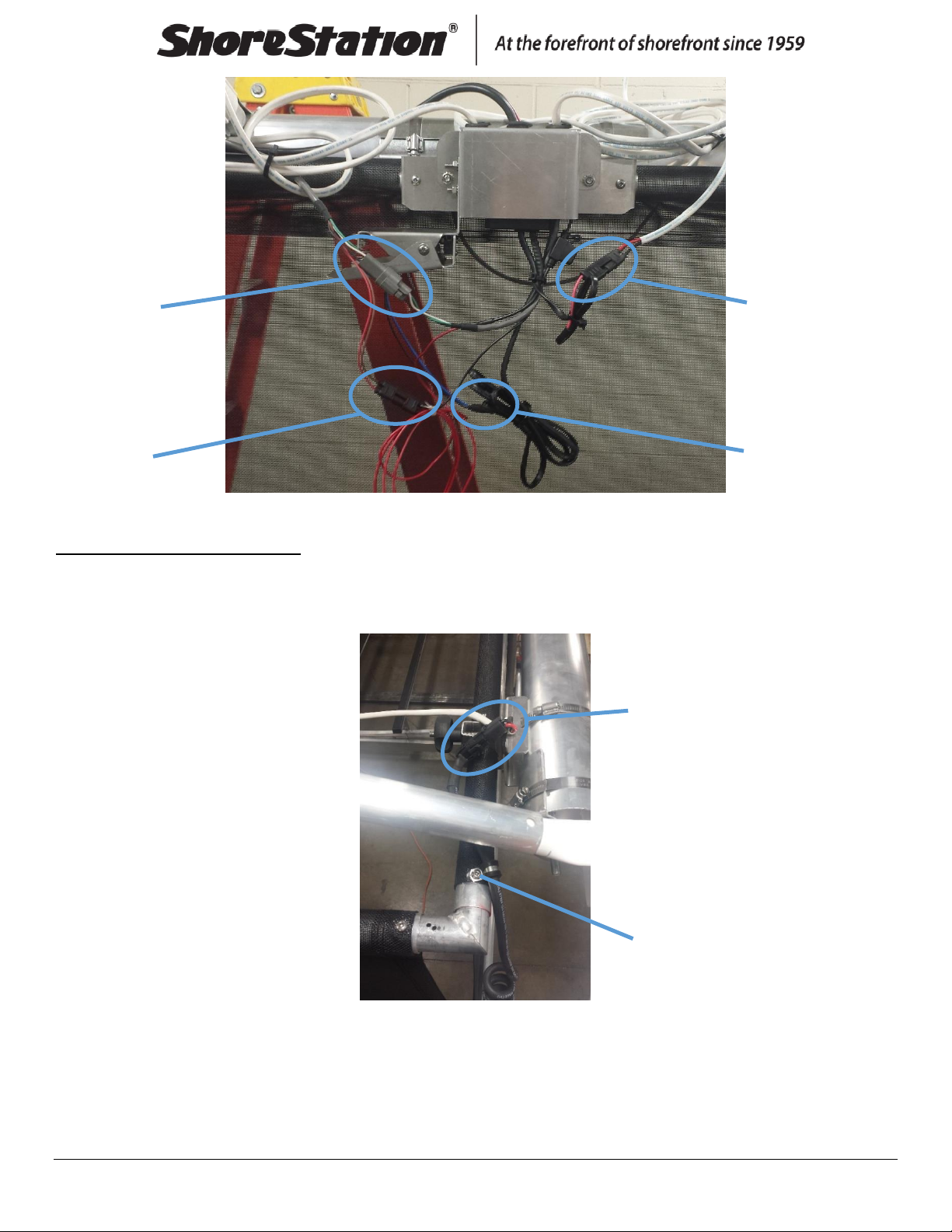
19 –Motor Connection Callouts
Motor- Direct the extension harnesses down the boathouse roof toward the motor corners and secure them
along the way. Unscrew a self-tap screw, run the motor cord through the clamp, tighten the self-tap screw
back in place, and connect the harness and motor cord (as shown).
Backwind extension
harness (only for
models previous of
8-29-2016)
Self-tap
screw
Upper limit
switch connect
Toggle switch
connect
Power connect
from toggle box
Motor
Connection

Document Number: 0004593
Rev: 1 Page 13
20 –Motor Connection Callouts
Make sure all the curtains are centered. In the idler corners only, self-tap a screw through the Keder strip and
into the roll tube (as shown), but stop when it hits the idler shaft.
21 –Power Cable
After all the assembly and power connections are made, attach the power cable to the battery- red is positive,
black is negative- and connect the gray connectors. Turn the power key on the toggle box to “ON.” Now the
toggle switch will run the curtain up/down. The fob remotes have been set at the factory to run the curtain on
mode 2. Activate the fobs, select mode 2, and push up/down to move the curtain.
Self-tap screws

Document Number: 0004593
Rev: 1 Page 14
Pairing the ShoreScreen Wireless Controls with your Boat Lift
This process pairs the new wireless remote controls that came with your ShoreScreen Power Curtain with your ShoreStation
FlexPower Boat Lift. The wireless remotes provided with your ShoreScreen Power Curtain have been pre-paired with the
ShoreScreen’s control system. This process involves unlocking the remote control and pairing Mode #1 with the boat lift’s controller.
NOTE: The ShoreScreen wireless controls are compatible with ShoreStation FlexPower Hydraulic and FlexPower Electric (EDS)
control system. The controls will not work with other brands or older ShoreStation control systems. If your boat lift’s remotes do
not look similar the remotes provided, then the systems are not compatible.
Unlock the Wireless Remote Control
Lock mode is indicated by all 5 Mode Indicator lights flashing when a button is pressed on the key fob. To unlock the key fob, hold
both the Up and Down buttons at the same time for 3 seconds. The mode indicator light will flash indicating that the key fob is
unlocked. If no button is pressed for 3 minutes, the key fob will automatically go into lock mode and will need to be unlocked again.
Repeat for All Wireless Remotes
Repeat the steps for all wireless remotes provided with your boat lift that you want to operate the ShoreScreen.
NOTE: The pairing process differs between Hydraulic and Electric (EDS) systems. Please select the appropriate process based on
your lift
Pair the Wireless Remotes with the ShoreStation Hydraulic Boat Lift
To pair with the system, all remote controls need to be available and unlocked. Make sure all wireless remotes are in Mode #1. The
lift must also be enabled by turning the lockout key to the ON position.
2014 and newer models are placed into pairing mode by tripping the top limit switch of the boat lift 10 times within 30 seconds. The
controller will flash the light 1 output twice indicating it is in pairing mode. If you do not have a light plugged into the light 1 output,
listen for the controller ‘click’.
Make sure the wireless controller is in Mode #1. Press the ON (UP) button on each wireless remote once to pair with the controller.
The Light 1 output will flash each time a remote button is pressed during pairing mode. A maximum of 5 remotes can be paired at
once.
Figure 1 –Key Fob

Document Number: 0004593
Rev: 1 Page 15
Pair the Wireless Remotes with the ShoreStation Electric (EDS) Boat Lift
To pair with the system all remote controls used with the lift need to be available and unlocked. Make sure all wireless remotes are
in Mode #1. The lift must also be enabled by turning the lockout key to the ON position.
FlexPower Electric Lifts are placed into pairing mode by pressing the button on the back
of the controller mounted inside the winch system. To access the controller, the front
cover must be carefully removed. The pairing button is located on the back of the
controller (Figure 2). Press and hold the button until the controller beeps indicating it is
in pairing mode.
Make sure the wireless controller is in Mode #1. Press the ON (UP) button on each
wireless remote once to pair with the controller. The winch controller will beep each
time a remote button is pressed during pairing mode. A maximum of 5 remotes can be
paired at once.
Test the Wireless Operation
Test the operation of the wireless by switching to Mode #1 using the Select button. Test the boat lift operation. Switch to Mode #2
(using the Select button) and test the curtain operation.
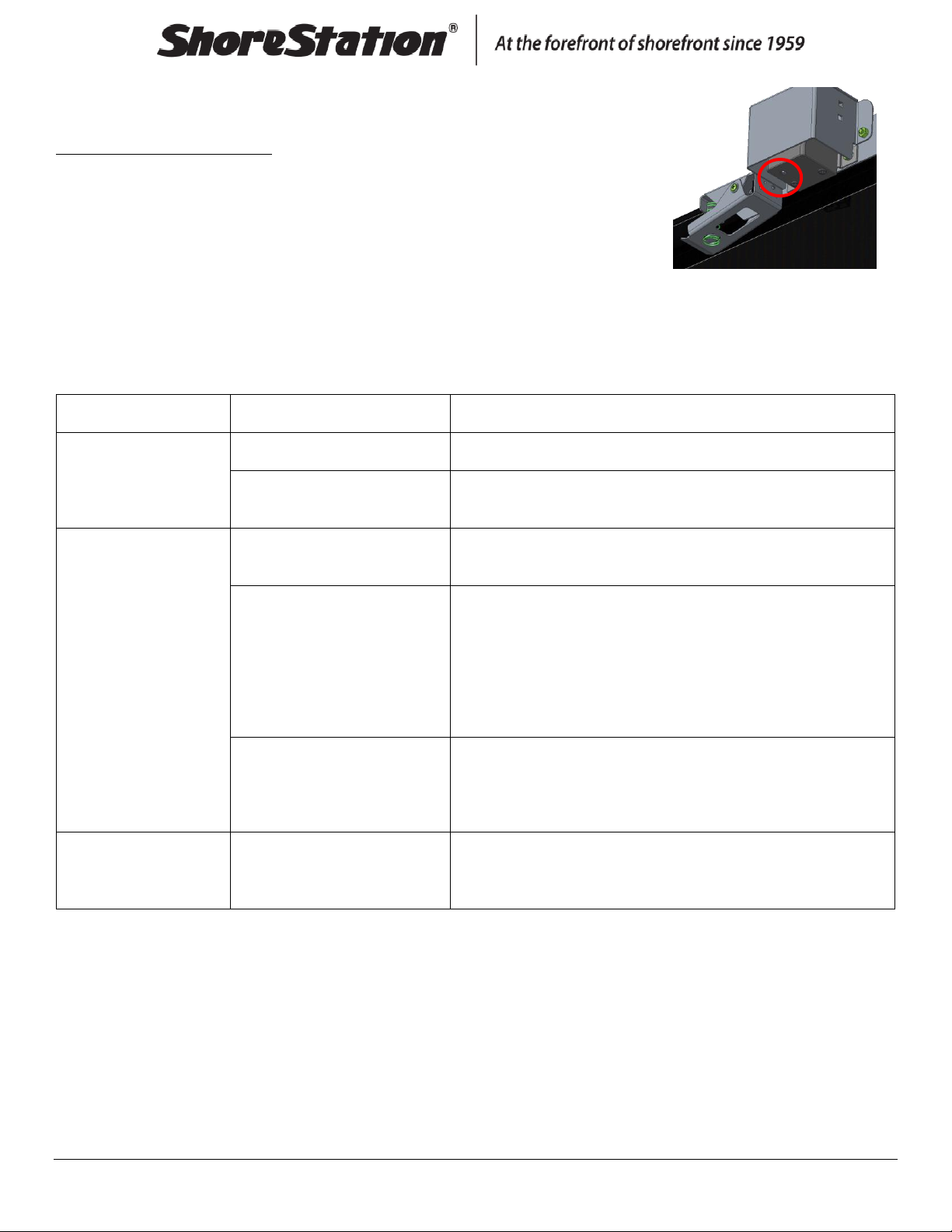
Pairing Existing FlexPower Controls
This process pairs the controls that came with your ShoreStation FlexPower Hydraulic or Electric boat lift. In this case, we will unlock
the Mode 2 of your boat lift’s wireless controllers and initiate the pairing process on the ShoreScreen’s controller (Figure 3).
Use the following steps to unlock the correct mode and pair with the ShoreScreen:
Figure 3 - ShoreScreen Control Location
Figure 2 - FlexPower Electric (EDS) Pairing
Button Location

Document Number: 0004593
Rev: 1 Page 16
Unlock the Wireless Remote Control
Lock mode is indicated by all 5 Mode Indicator lights flashing when a button is pressed on the key fob. To unlock the key fob, hold
both the Up and Down buttons at the same time for 3 seconds. The mode indicator light will flash indicating that the key fob is
unlocked. If no button is pressed for 3 minutes, the key fob will automatically go into lock mode and will need to be unlocked again.
When in the Mode Unlock state, the mode that is lit is either locked or unlock by pressing the ON (UP) or OFF (DOWN) buttons.
Continue to select ON or OFF until all the modes have been addressed.
The control will display the unlocked modes by lighting all of the unlocked Mode Indicator Lights. After 5
seconds, the control will go back into the normal operating state. This is indicated by the flashing light on
Mode 1.
Place the Wireless Remote Control in the ‘Mode Unlock’ State
To place the remote in the Mode Unlock State, press and hold the Select button down until the mode
indicator light stops flashing (about 10 seconds). The mode indicator light will be on Mode 1. The
controller is now in the ‘Mode Unlock’ state. The controller will automatically go back into the normal
state if no buttons are pressed for more than 5 seconds. If this happens, you will need to repeat this step.
Unlock Mode #2
ShoreStation FlexPower control systems reserve Mode #2 for the ShoreScreen Power Curtain operation.
With the remote in the Mode Unlock State, move through the modes by pressing ON or OFF to enable or
disable the indicated mode. When on Mode #2, press ON to enable it. Wait for 5 or more seconds until the
controller goes back into the normal operation state (flashing on Mode 1). To check to ensure Mode #2 is
unlocked, press and release the Select button. The mode indicator light should move to Mode #2.
Note: Do not unlock other modes unless you have installed the accessories for these modes (lights, limit
switches, etc.).
Repeat for All Wireless Remotes
Repeat the steps for all wireless remotes provided with your boat lift that you want to
operate the ShoreScreen.
Pair the Wireless Remotes with the ShoreScreen Controller
To pair the wireless remote controls with the ShoreScreen Controller, all remotes must have Mode #2
unlocked using the previous instructions. Make sure all wireless remotes are available and unlocked with
the Mode Indicator flashing on Mode #2.
Press and hold the pairing button located on the ShoreScreen controller (Figure 5). The controller should
beep once to indicate it is in pairing mode. If you have difficulty pressing the button, try using a ballpoint
pen to press it in further.
Make sure the wireless remote is in Mode #2 (mode indicator flashing on the second light). Press the ON (UP) button on the
wireless remote while in Mode #2. The ShoreScreen controller should beep once indicating it has been paired with the wireless
Figure 4 –Key Fob
Document Number: 0004593
Rev: 1 Page 17
remote. Repeat for each remote control (maximum of 5). Continue pressing the last remotes
UP button until the controller double beeps. The double beep indicates the controller has
exited pairing mode.
Test the Wireless Operation
Test the operation of the wireless by switching to Mode #1 using the Select button. Test the
boat lift operation. Switch to Mode #2 (using the Select button) and test the curtain
operation.
IF BOTH SYSTEMS ARE OPERATED FROM THE SAME MODE (EXAMPLE BOTH THE LIFT AND
SHORESCREEN OPERATE USING MODE #1), THE SHORESCREEN MUST TO BE RE-PAIRED TO
FIX THIS BY REPEATING THIS PROCESS.. DO NOT OPERATE THE SYSTEMS FROM THE SAME
MODE.
Troubleshooting
Symptom
Cause
Remedy
The wireless controller
does not unlock (no
flashing lights).
Dead Battery
Replace the Key Fob batteries with 23A 12V (requires 2).
Damaged Remote.
Contact your ShoreStation dealer to get a replacement wireless
controller.
The ShoreScreen
Controller will not go into
Pairing mode.
The lockout key is in the off
position.
Turn the lockout key to the ON position and try the pairing button
again.
The lift battery is dead,
disconnected, or incorrect
polarity.
Check the connections between the ShoreScreen controller and the
boat lift battery.
Check the Polarity of the connection to make sure the polarity is
correct.
Check battery charge using a battery tester or try another battery.
The controller or lift battery fuse
is blown.
Check the 5A mini blade fuse on the ShoreScreen controller harness.
If your lift is equipped with a terminal fuse, check it to make sure it is
not blown.
Mode #1 runs both the
boat lift and the
ShoreScreen.
Incorrect pairing.
Repeat the pairing steps with the ShoreScreen controller and ensure
you are in Mode #2 when pairing the remote transmitter.
If the problems stated above do not describe the issues you are experiencing, contact ShoreStation at (800) 859-
3028.
Figure 5 - ShoreScreen Controller
and Pairing Button
This manual suits for next models
11
Table of contents


