SHOWERFORCE 911-M Mounting instructions

NewTeam Ltd.
Customer Service Dept.
Brunel Road
Earlstrees Industrial Estate
Corby
Northants
NN17 4JW
1st Fold
2nd Fold
3rd Fold
✁
Please tape down
Please tape down
Affix
Stamp

Installation Instructions
and User Guide
PLEASE KEEP THIS BOOKLET
FOR FUTURE REFERENCE
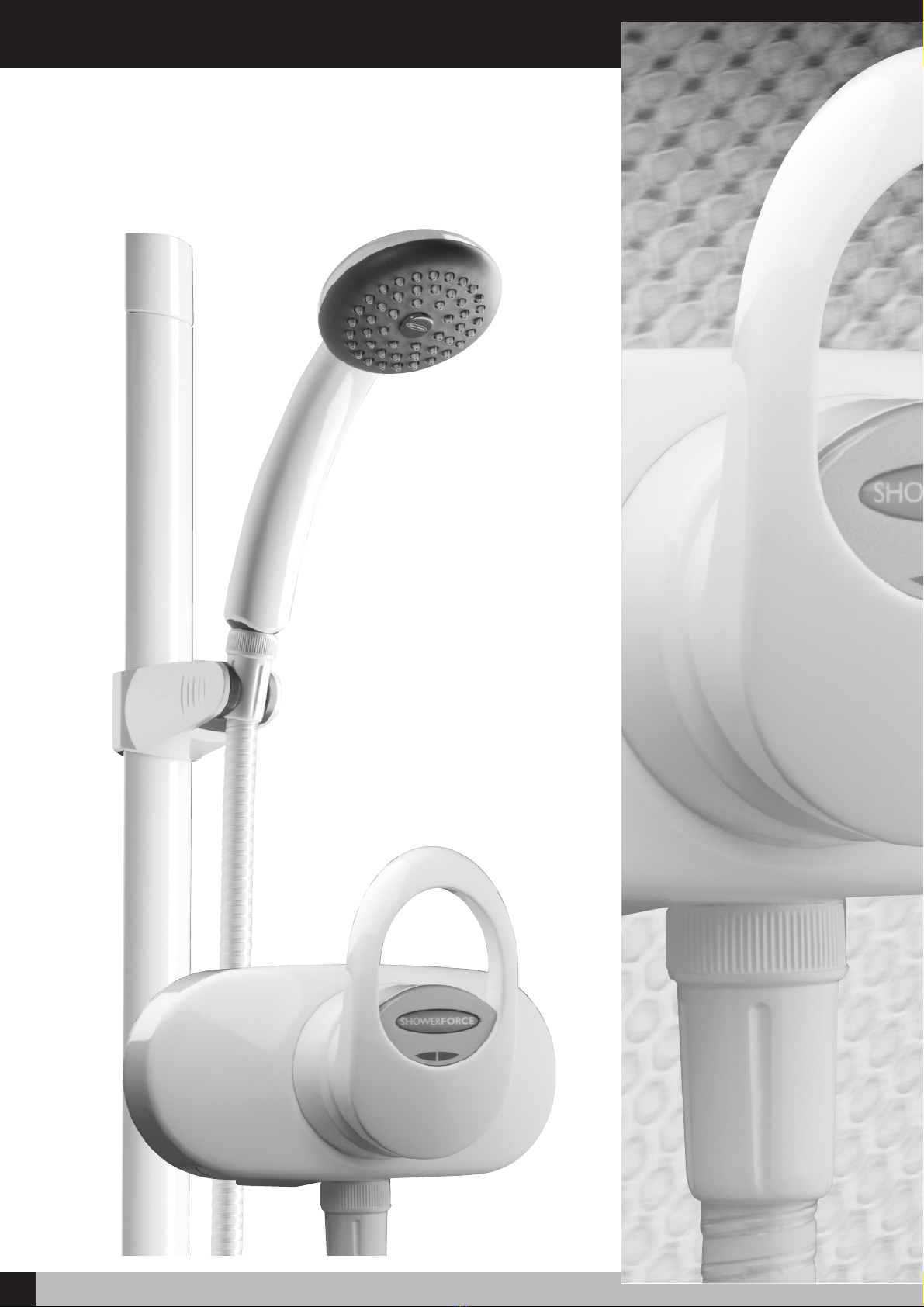
SHOWERFORCE 911-M
MANUAL MIXER SHOWER
DEAR INSTALLER WHEN YOU HAVE READ THESE INSTRUCTIONS
PLEASE ENSURE YOU LEAVE THEM WITH THE USER
IN THE EVENT OF ANY QUERY PLEASE CONTACT
THE NEWTEAM CUSTOMER HELPLINE
Tel : 01536 264 012
Product Features
1SHOWERFORCE 911-M SHOWER VALVE
ShowerForce 911-M

Contents
2
SHOWERFORCE 911-M SHOWER VALVE
Please read this booklet carefully and ensure a competent person undertakes the
installation.
Note: Following the headings in sequence will guide you through the installation
and operation of your ShowerForce 911-M Mixer Shower
PLANNING YOUR INSTALLATION
FITTING YOUR SHOWER
• Plumbing
• Surface Mounted Fixing
• Recessed Fixing
USER INSTRUCTIONS
ADJUSTING MAXIMUM TEMPERATURE
COMMISSIONING
Refer to back cover for Guarantee, Customer Service and Replacement Parts Policy.
In the event of any query regarding installation please contact the NewTeam Customer
Service Department
Tel: 01536 264 012 • Fax: 01536 409 201
In line with our policy of continual product development the specifications may be
varied and product design altered. We reserve the right to depart from the details
given in this manual without prior notice.
3
Pages
4
5
7
7
Installation and Operating Instructions
for ShowerForce Manual Mixer Shower
• 911-M
SPARE PARTS 8
GUARANTEE 10
FIXING YOUR SHOWER 6

Planning Your Installation
3SHOWERFORCE 911-M SHOWER VALVE
911-M
• Make your connection into the hot water supply from the cylinder ensuring
that it is the first draw off below the expansion pipe tee. (Fig. 1).
• If this is not possible, a direct connection must be made from the hot water
cylinder with an Essex flange.
• The cold water should be taken directly from the cold water storage tank
and must be positioned 60mm below the cold connection to the hot water
cylinder, Fig 1.
• It is recommended that non restrictive isolating valves are incorporated
into the shower supply pipework.
• The temperature of your stored water must not exceed 65ºC. A stored
water temperature of 60ºC is considered sufficient to meet all normal
requirements in line with the British Standard 6700.
General
Hot Water Tank
Cold Water Storage Tank
1m. (39”) min.
Fig 1 - Typical Installation Diagram
Mixer
1 Metre
Min.
60mm
Cold Hot
Mains
Water
Supply
Fitting Your Shower
4
SHOWERFORCE 911-M SHOWER VALVE
Fitting your Shower
• Determine the position at which the mixer valve is to be installed. This is normally
chest height, - approximately 1 - metre above the bath base or shower tray.
• If the pipework is to be concealed, or the valve is to be recessed, the pipes should
be installed at this time.
• If surface mounting the valve with concealed pipework, the pipes must terminate
15mm above the finished wall surface.
• If the valve is to be recessed, a channel must be prepared for the valve and
pipework, approximately 140 mm wide and between 40 and 60 mm deep, with
the pipework terminating at 96 mm centres.
• In all cases the pipes should be installed with the hot supply on the right hand
side viewed from the front. If the pipework is reversed, a "reverse indice" may be
obtained from Showerforce Customer Service department.
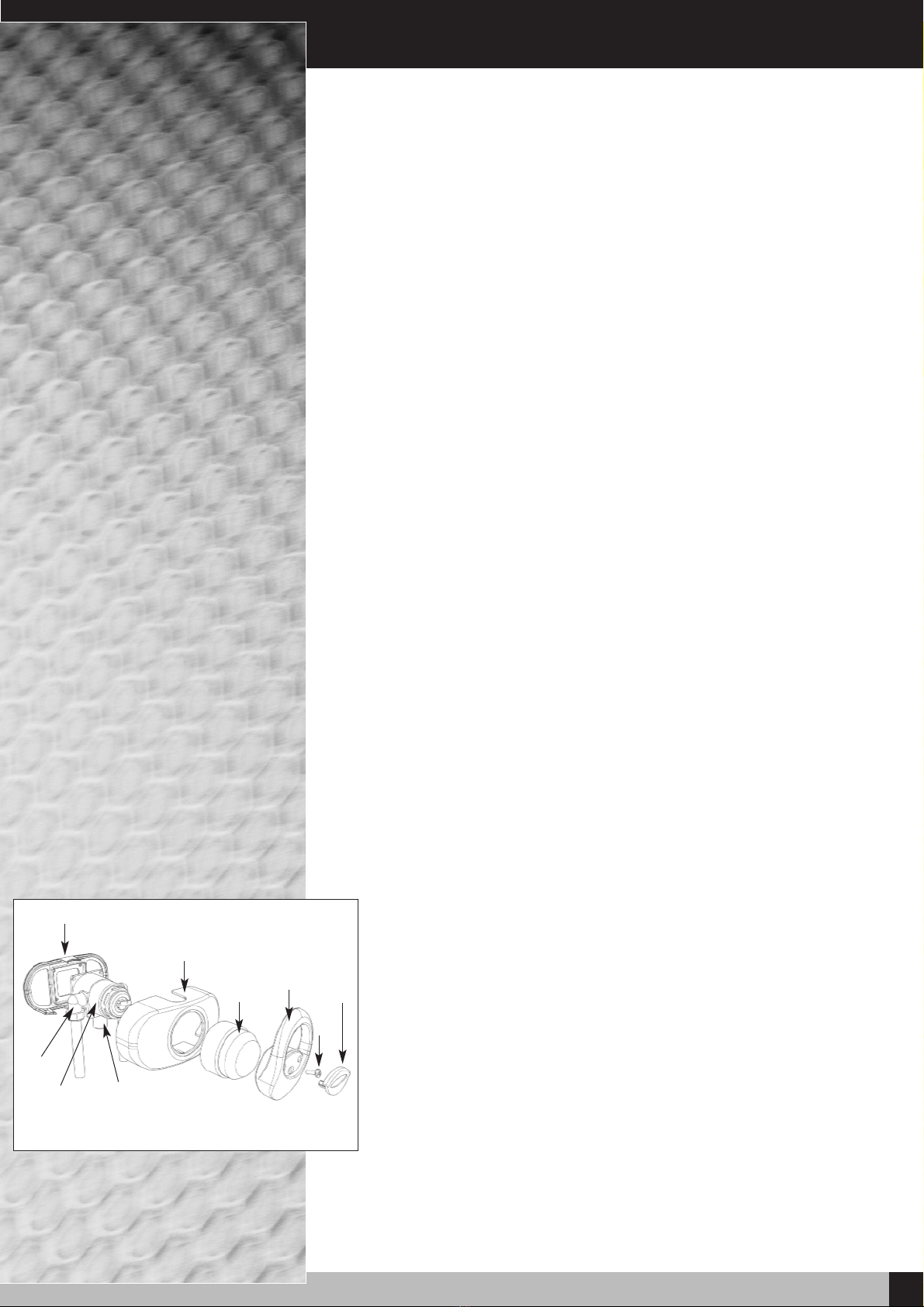
• Before commencing installation, remove the retaining ring and shroud, and
identify all components using the illustration and parts list.
Plumbing
Surface Mounted Fixing - Fig 2
• Remove the inlet elbows (1) from the valve body (2) and, using a few turns of PTFE tape
to seal, refit in the final position for the required pipework entry, i.e. top, bottom or rear.
Using PTFE tape to seal, screw the shorter (chamfered) end of the outlet nipple (3) into
the valve body.
• Position the wall bracket (4) against the wall and mark the two upper fixing holes on
the wall. Drill the wall at the marked positions, and insert the wall plugs supplied. Fix
the wall bracket and valve using the screws supplied.
NOTE.
• The wall bracket is used for top, bottom or concealed (rear) pipe connection. The two
inlet caps should be pulled off the bracket for top and bottom feed – the illustration
shows the position for bottom feed, it must be turned through 180 degrees for top
feed. For concealed entry, the inlet caps should be left in position as received, and the
bracket fixed to the wall as for bottom pipe entry.
• Bring the inlet pipework to the valve. Flush out the pipework and connect using the
15mm compression nuts and olives supplied.
• Place the shroud (5) over the valve with the apertures in appropriate positions to
accommodate the inlet pipework and outlet nipple. If the valve has concealed inlet
pipes, ensure that the pegs on the inlet caps locate correctly in the holes in the shroud.
• With the shroud in place, screw the retaining ring (6) onto the valve body, fit the handle
(7) to the shaft, and secure using the screw supplied (8).
• Insert the indice (9) into the recess in the handle and press into place.
• Fit the outlet cap into the hole in the top of the shroud. The wide, raised slot in the
cap fits into the rear (wall side) slot in the shroud hole.
4
Fig. 2 - Diagram of Surface Mounted
Mixer Valve
5
6
7
8
9
1
23

5SHOWERFORCE 911-M SHOWER VALVE
Fitting Your Shower
Recessed Fitting - Fig 3
• It is essential that when installing a recessed mixer valve, full access to the
valve can be achieved for servicing purposes. Rear access to the mixing valve is
always preferred wherever possible, (e.g. airing cupboard or panelled wall)
as this removes the need to disturb any tiling or decorative features at the front
of the valve. Isolation valves should be fitted on both supplies and ensure that they are
accessible and maintained.
• Position the valve body (2) in the recess and mark the fixing screw positions on the wall,
drill the wall and insert the wall plugs supplied.
• Remove the inlet elbows (1) from the valve body and, using a few turns of PTFE tape
to seal, refit in the final position for the required pipework entry, i.e. top, bottom or rear.
Using PTFE tape to seal, screw the longer, flat end of the outlet nipple into the valve
body. Fix the valve to the wall, flush out the pipework and connect using the 15mm nuts
and olives supplied.
• Determine the position for the shower union elbow (3), and using a length of 15mm
pipe and suitable fittings, connect to the valve outlet nipple. The union elbow requires
a 1/2” BSP female FI connection.
• If conditions permit, it may be possible to make
the connections prior to finally fitting the valve to
the wall.
• Make good the wall as necessary, and fit the recessed
cover (4) over the valve body and secure using the
2 x 35mm screws supplied.
• Fit the handle and indice as described in the surface
mounted instructions (above).
Fig. 3 - Diagram of Recessed Mixer Valve
1
3
4
2
Commissioning
• Ensure the mixer valve is in the "off" position (see User Instructions), but do not
connect the handset. Turn on the cold isolating valve, and run the shower on the
cold setting for 2-3 minutes to clear any debris from the pipework.
• Attach the handset to the hose, and turn on the hot water isolating valve. Run the
shower in the full flow position, and starting with the handle full left (max. cold),
gradually turn the handle clockwise to the full right extreme (max. hot), noting the
temperature rise.
• If the temperature does not rise, suspect supplies are connected the wrong way
round, check and either correct, or obtain a reverse indice from Showerforce
Customer Service.
• If the temperature is too hot on the full hot position, it is necessary to either adjust
the hot water temperature, or set the temperature limit stop.

6
SHOWERFORCE 911-M SHOWER VALVE
Before proceeding with fitting the rail, identify each of the items
supplied using the illustration.
The slider need not be removed from the rail during fitting. The top of
the slider has a smooth profile, whereas the underside has a recess
revealing the grooves on the handset holder.
Fit the hose retainer onto the bottom end of the rail and secure using
the small screw from the kit.
Position the rail on the wall, bearing in mind the heights of people
likely to use the shower, and the length of the hose when connected to
the shower and passed through the hole in the hose retainer. Mark the
wall to indicate the upper fixing screw position. Screw centres are 605
mm (approx. 23 inches,) apart.
Drill the wall at the marked fixing position using a 6 mm drill, and
loosely fix the rail end, checking that the rail is hanging vertically using
the spirit level incorporated into the top end of the rail. The bubble
should be exactly between the two lines on the spirit level body. Mark
the position for the lower fixing screw, move the rail to one side, drill
the wall, and fix the lower end of the rail.
Check that the rail is vertical and tighten both fixing screws.
Slide the end cap into position on the top end of the rail, and fit the
screw cover into the recess in the hose retainer.
When fitting the hose, it should pass through the hole in the hose retainer.
Hose connections should be handtightened only.
NOTE: The hose nut, and not the handset handle, fits into the slider,
and the slider moves more freely on the rail if gripped next to the rail,
rather than at the handset.
Spirit Rail Kit
No Part Description
1Rail end cap
2Spirit level
3-4 Rail with slider attached
5Hose retainer & Gel Hook
6Screw cap
7Hose retainer fixing screw
Rail fixing screws &
wall plugs
1
2
3
4
7
5
6
Fig 4 - Riser Rail
Fitting Your Shower Rail
Adjusting Maximum Temperature
7SHOWERFORCE 911-M SHOWER VALVE
The mixer valve allows the showering temperature to be set at a safe level, preventing
accidental selection of high temperatures. This setting should be made during
commissioning and will require that the hot water cylinder is at its normal operating
temperature.
Procedure:
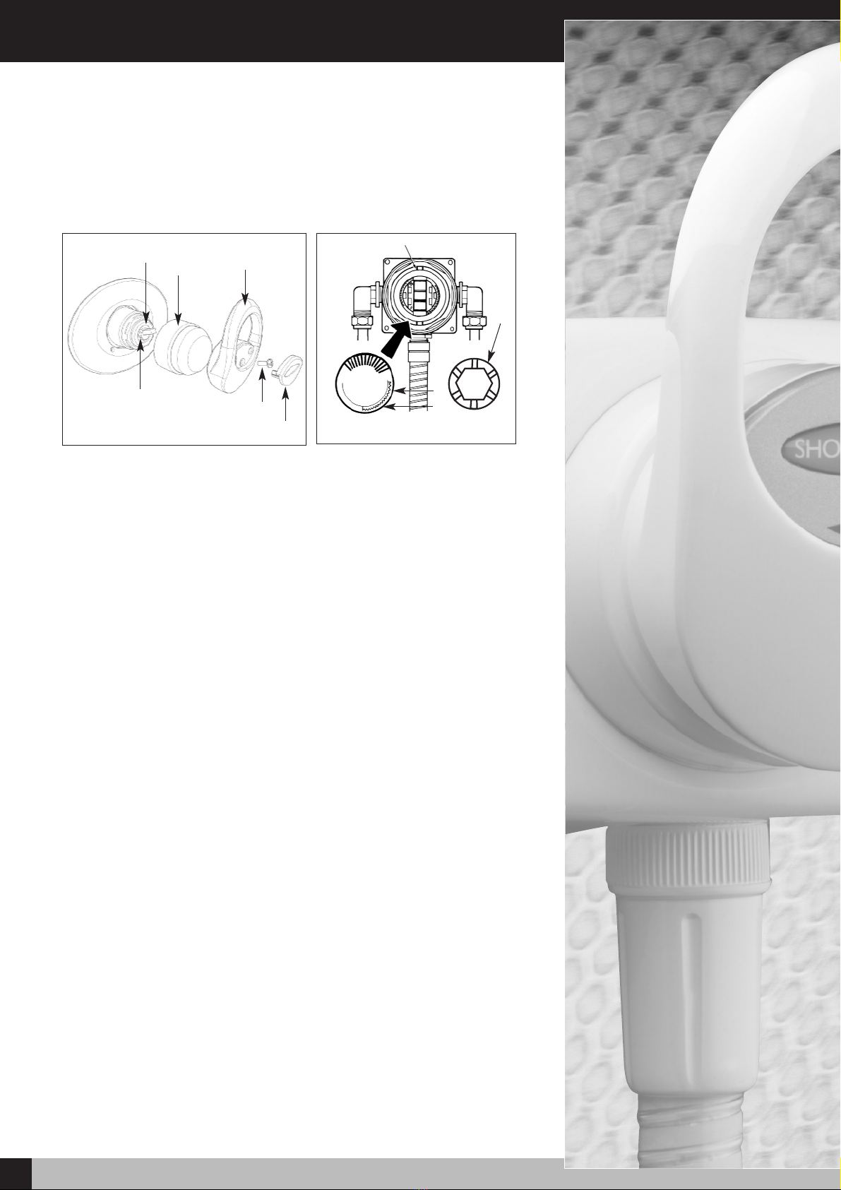
Refer to Fig 5 & Fig 6
• Prise out the indice (1) from the recess in the handle, and remove the handle
fixing screw (2).
• Remove the handle (3) and retaining ring (4).
• Prise off the clear temperature limit ring (5), and the green flow selector (6).
• Refit the handle to the mixer shaft, turn on the shower, and adjust the
temperature to approximately 5ºC above the comfortable showering level.
• Turn off the shower but retain the temperature setting. Refit the temperature limit
ring with the limit stop (7) touching the lower side of the pin (8) through the mixer
shaft.
• Refit the handle and check that the temperature is acceptable. Adjust as
necessary as above.
• Refit the flow selector with the "Max" slot in the 6 o’clock position.
• Refit the handle, insert the handle fixing screw and fit the indice.
User Instructions
• Pull the valve handle towards you (Fig 5) water will begin to flow from the handset.
• To regulate the water flow and pressure of your shower gently move the valve
handle (3) to and from the ‘off’ position.
2
1
67
8
5
6
Fig 6
Fig 5
5
43
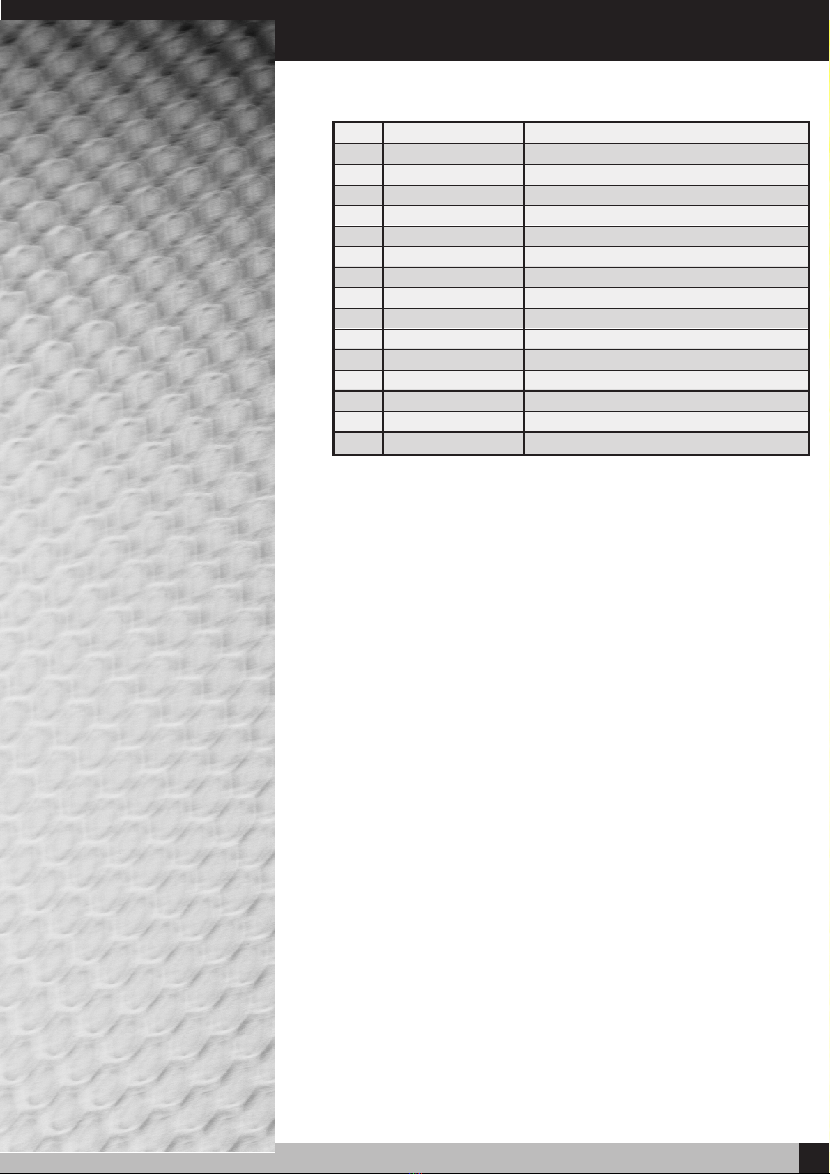
Spare Parts
8
SHOWERFORCE 911-M SHOWER VALVE
1. SP-075-0016 Lever Fixing Cover
2. SP-075-0015-WT Handle
3. SP-075-0017-WT Recess Shroud
4. SP-075-0018-WT Surface Shroud Front
5. SP-075-0012-WT Retaining Sleeve - C/Mix-T
6. SP-075-0019-WT Surface Shroud Rear
7. SP-075-0020-WT Outlet Cap (Not Shown)
8. SP-075-0021-WT LH Inlet Cap (Not Shown)
9. SP-075-0022-WT RH Inlet Cap (Not Shown)
10. SP-088-0321 Laser Insert Prntd Showerforce
11. SP-075-0024 Recess Shroud Surface Seal (Not Shown)
12. SP-075-0025 Recess Shroud Collar Seal (Not Shown)
13. SP-280-0500-WT Spirit Rail & Slider Assembly (Not Shown)
14. SP-280-0032 Hose Retainer & Gel Hook (Not Shown)
15. SP-285-0820-WT Hose (Not Shown)
16. SP-168-0211-WT Handset (Not Shown)
Guarantee/Service Policy
9SHOWERFORCE 911-M SHOWER VALVE
Part No. 404-0103 Issue 06/02
Guarantee
Thank you for purchasing a ShowerForce product, which has been designed, manufactured and
tested, in the U.K., to the highest standards, by NewTeam Ltd.
Guarantee. 2 Years, 1 Year - Parts and Labour Second Year- Parts Only
This is provided that:
1. The guarantee registration card is completed and returned within ten days complete with a copy
of proof of purchase.
2. The product is installed and operated in accordance with our instructions and has not been
misused or damaged.
This in no way affects your statutory rights as a consumer.
The information on the Guarantee card helps ShowerForce to process any claims and contact you
about your product and its maintenance if required. The registration of your personal details is
purely for Showerforce use, and the other information helps us to make products for the future.
ShowerForce Shower products are designed, manufactured and tested to the highest standards.
Should a complaint arise, products are guaranteed against faulty workmanship and materials for a
period of 12 months from the date of purchase, when in domestic use (second year guarantee is parts
only). For your guarantee to be valid, your shower pump must be installed by a competent
person, in accordance with the instruction manual.
ShowerForce will repair or replace (at our option), free of charge, any faulty components during the
guarantee period, provided it has been maintained and operated in accordance with our
instructions, and has not been misused or damaged.
Modification or repair of this product by person(s) not authorised by ShowerForce will invalidate this
guarantee.
This guarantee applies to products purchased within the United Kingdom or Republic of
Ireland, but does not apply to products used commercially.
This guarantee does not affect your statutory rights.
Service Policy - Replacement Parts Policy
IMPORTANT:
In the event of product or component malfunction, DO NOT tamper with or remove the product
from site. Telephone ShowerForce Customer Service Department on 01536 264 012 and be
prepared with the date of purchase, model number and a description of the complaint.
Our service staff are fully qualified to advise on correct installation procedures and will be able
to diagnose whether the fault will require a replacement part or a visit from a ShowerForce
engineer.
If required, a service call will be booked, and either yourself or an appointed representative (who
should be a person of 18 years or over) must be present during the visit.
All site visits to product within the guarantee period will be carried out free of any parts or
labour charges provided the conditions of the guarantee have been adhered to. (Second year
guarantee is parts only)
All site visits to product out of guarantee will be subject to charges for parts and labour which
is payable by you or your appointed representative at the time of the visit. Charges will also be
levied on cancelled appointments, unless advised to ShowerForce at least 24 hours in advance
of the agreed date and time.
We reserve the right not to undertake work where payment cannot be made to our engineer at
the time of the visit.
ShowerForce hold stocks of components for all their range of products and these will be
maintained for the duration of their life.
Should a product be discontinued, spare parts stocks will be maintained, but in the event of a
part becoming unavailable ShowerForce reserve the right to supply a substitute of equal quality.
The following payment methods can be used to obtain spare parts:
By post, pre-payment of proforma invoice by cheque or postal order.
By telephone quoting credit card (Mastercard, Visa or Visa Delta) details.
REPLACEMENT PARTS:
CUSTOMER SERVICE HOTLINE:
Guarantee
10
SHOWERFORCE 911-M SHOWER VALVE
Please post immediately enclosing a copy of proof of purchase
GUARANTEECARD
ShowerForce 911-M Mixer Shower
Proof of purchase enclosed
YES ❐NO ❐
NAME:
ADDRESS:
POSTCODE:
DATE OF PURCHASE:
PRODUCT PURCHASED FROM:
TOWN:
ShowerForce/NewTeam’s philosophy is to offer outstanding products with quality and
integrity, please help us by taking the time to answer the following questions. Thank you.
POST BACK
FOLD AND TAPE AS INSTRUCTED OVERLEAF
MARKETING INFORMATION
1. Please state your profession: Plumber
❒Builder ❒Electrician ❒Customer ❒
Other ❒(please specify) ______________________________________________________________
2. Please state the reason for purchasing a shower: New Build
❒Replacement ❒
Renovation ❒Other ❒ (please specify) ________________________________________________
3. If the product is a replacement shower, please state the type and make of the shower it is
replacing: ____________________________________________________________________________
4. What influenced you to purchase the 911-M Mixer Shower? Advertisement
❒
Trade Press
❒Recommendation from Stockist
❒Recommendation from Installer
❒
Other ❒(please specify) ______________________________________________________________
5. Please state your main reason for purchasing the 911-M Mixer Shower:
ShowerForce Product Knowledge ❒Product Features ❒Product Styling ❒Price ❒
Other ❒(please specify) ______________________________________________________________
Please tick here if you do not require any further information or product updates from NewTeam
❒
FOR SHOWERFORCE USE
This label identifies your product and
provides all the information needed
AFFIX PRODUCT LABEL HERE
✁
Table of contents


