ELECTRIC TOILET BASE KIT
FEATURES
•High Capacity Macerator and Bowl Scavenger Pump
•Flexible Impeller Flush Pump
•Permanent Magnet Type Motor, Fully Enclosed,
with Stainless Steel Shaft
•Complies with USCG 183.410 and ISO 8846
MARINE for Ignition Protection
•Simple Push Button Switch included
•All Corrosion Resistant Materials for Marine Use
SPECIFICATIONS
•5/8"or 3/4"Inlet, 1"Outlet Back Flow Check Valve
in Discharge
•1"x 1-1/2"Hose Adaptor included to adapt to 1-1/2"
waste plumbing.
•Thru Flow Approx. 1-1/2 Qts. per 5 Seconds of
Operation
VARIATIONS
MODEL NO. DESCRIPTION
37010-0092* Toilet Conversion, 12 Volt EMC
37010-0097* Toilet Conversion, 24 Volt EMC
*This model is Marked and complies with EN50081-1 for
suppression of electro-magnetic interference.
APPLICATION
The Jabsco electric toilet may be installed above or below
the waterline. Flush pump is self-priming with a vertical lift
up to 4 feet; discharge macerator pump can operate
against a vertical head up to 4 feet.
The 37010 series can be used to convert the Raritan PH
or Compact, Wilcox-Crittenden “Head Mate”, Groco HC,
Brydon No. 9127, 9128, or No. 59128 and virtually any
other model marine toilet using the “standard” bowl config-
uration with a 3-3/4"diameter bolt circle, 4 hole pattern in
the base. Check the dimensional drawing to be sure the
bowl will fit the flange dimensions as shown.
The 37010 series includes the complete motorized base
assembly, bowl gasket, four bolts and washers for bowl,
two 5/8"to 3/4"pump port adaptors, 3/4"white hose, 1"to
1-1/2"discharge port adaptor, and momentary control
switch.
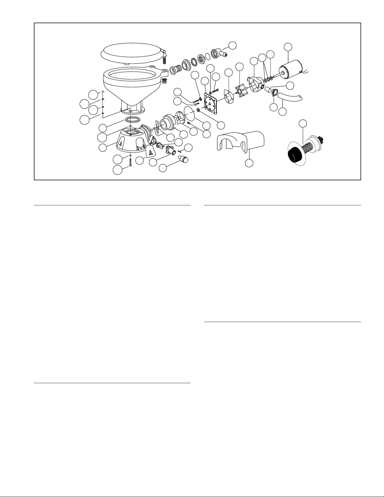
ASSEMBLY
1. Overall height after conversion may increase up to 1"
on some models, check to be sure adequate space is
available if located under seats or bunks.
2. Screw 6mm machine screws with starlock washer
under each head into nuts positioned in the hex recess
on the top of the base to form bowl attachment studs
(see exploded view).
3. Remove complete manual base assembly and mount
bowl on Jabsco motorized base. NOTE: M6 x 50mm
long machine screws supplied are suitable for most
bowls; however some bowl flanges are heavier and
longer machine screws must be used. Place plastic
washers against bowl flange, positioning base for
most convenient hose connection arrangement.
4. Connect pump outlet to rear bowl connection with 3/4"
hose. Install the hose clamp on the pump discharge
port only.
5. Position complete toilet assembly and fasten securely
on flat surface. Be sure not to warp toilet base when
tightening toilet base down.
6. Connect existing inlet hose to pump inlet port. A 5/8"to
3/4"sleeve adaptor is included for fitting to commonly
used 3/4"inlet hose size. Make sure all connections
are airtight and free of sharp bends or restrictions.
7. Connect 1"discharge hose to discharge port (1-1/2"
hose when using 1-1/2"discharge adaptor) and make
suitable connection to holding tank or other discharge
system. Avoid sharp bends or restrictions.
8. For installation below the waterline, install a vented
loop in the intake hose and position about 8"above the
waterline at all angles of heel or trim. **A vented loop
should also be used for discharge if connected to a
thru-hull fitting.
9. For installations above water line, make a loop in dis-
charge line about 8 inches above base of bowl to
retain water in bowl. Some installations may need a
Model 37010-Series
Model 37010-Series
Conversion Kits