SHURflo Comfort Air 275-3330 User manual
Thank you for purchasing this fan from SHURflo. Please take a few minutes to read this entire manual before attempting
installation. If you have any questions, please contact your nearest dealer or SHURflo. This unit will work at an infinite
range of speeds in automatic or manual modes at a wide range of temperature settings. Automatic dome-sensing control
allows it to work with most vent covers. Automatic shut-off when it’s raining and motor thermal protection are just a couple
of the exciting safety features of this fan.
Standard Features
•True Variable Speed Fan
•Easy-Remove Screen
•Fits Standard 14” x 14” Roof Openings
•Thermally Protected Motor
•High-Amp Dome Safety Control
•Remote-Control
•Intake & Exhaust Operation
•Motorized Dome
•Automatic Rain Sensor
•Auto-Temp Control from 60°F –100°F
Contents
•1 Comfort Air™ Fan Unit, including
-1 upper unit
-1 internal flange & 4 screws
oSupplied trim fits roofs 3-1/2”-5-1/4”
See specifications on page 4 for trim
model # for other roof sizes
•1Remote Control
•1 Remote Wall Mount & 2 screws
•1 9-Volt DC Remote Control Battery
•1 Installation and Operation Manual
Location
•Fan must be installed with the hinge facing
the direction of travel.
•Locate bi-directional fan at least 3 feet from
any exhaust vent.
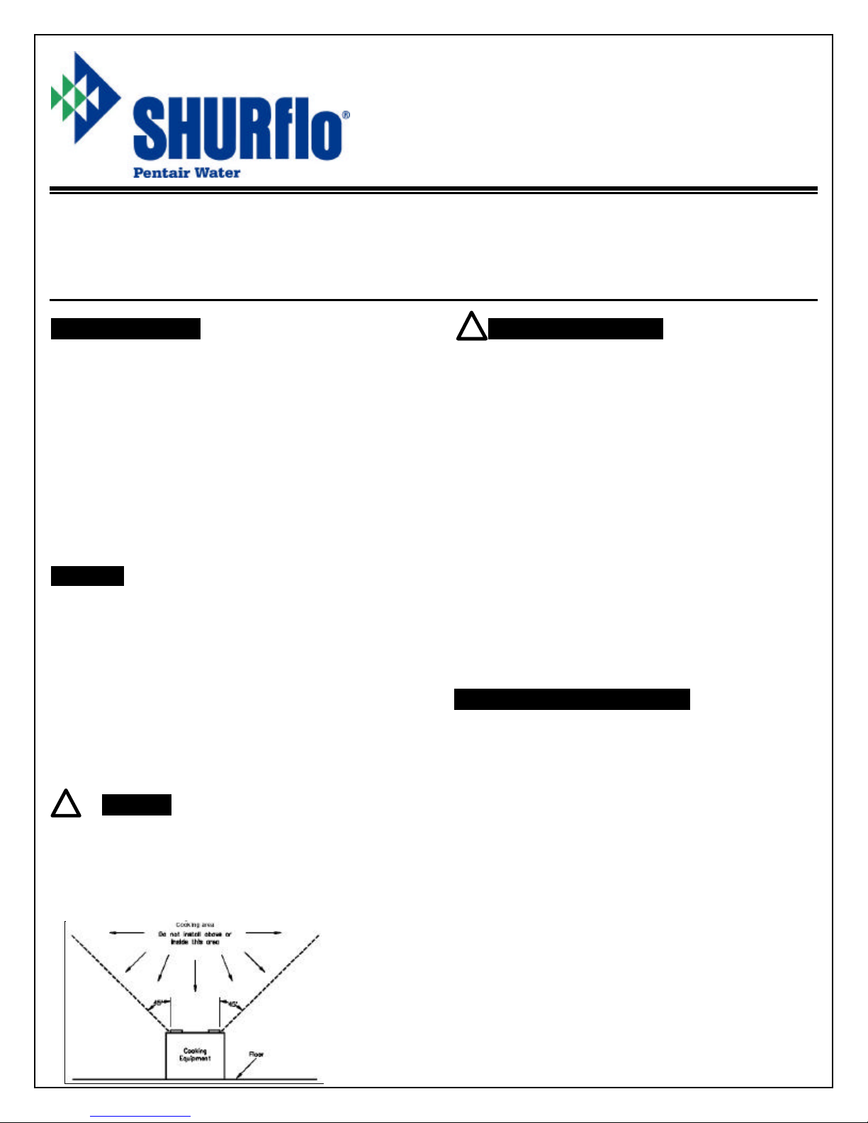
lDo not install fan in cooking area.
Important Information
•SHURflo recommends professional
installation.
•Please read the entire manual before
attempting installation.
•This unit requires 12 VDC Power only.
•This fan uses 5 Amps. Use 6A fuse.
•Follow all local building / electrical codes.
•Black wire is negative ground [ -].
•Red wire is positive power [ + ].
•Never reverse polarity. Reverse polarity can
damage circuit board.
•Never turn the fan on with the screen
removed.
•Always turn off power before removing
screen.
•Never place any objects in moving blade path.
Tools and Materials Required
•#2 Philips screwdriver
•Scraper
•Wire stripper/crimp tool
•Butyl sealing tape (1/8” x 1” x 6’)
•18 Gauge or larger copper stranded wire
•Insulated wire connectors
•6-Amp fused circuit
•All weather Silicone sealant
---Rubber roofs require EPDM sealant
•3/4” or 1” x #8 self-tapping screws [ 28 ] for
roof mounting. Screws removed from old
unit can be used.
Comfort Air™
Fan with Remote
Installation and Operation Manual
Models 275-3330 / 275-3331
911
-
724
-
A 04/05
page 1 of 4
!
!

jFan Hi Fan Speed Increase +
Press this button to increase fan speed.
kFan Off Fan Stop & Power Off
Press this button to stop the fan in Manual.
Press this button to exit Auto Mode [fan will
stop and dome will close].
lFan Lo Fan Speed Decrease –
Press this button to decrease fan speed.
mDome Open
Press this button to Open the Dome.
nDome Stop
Press this button to Stop the Dome.
oDome Close
Press this button to Close the Dome.
pExhaust / Intake
Press this button to change fan direction.
Thermostat Control & LED Light Bank
Adjust fan temperature from
60°F [green lights] to 100°F [red lights]
Remote Reset
Left green light and right red light are used
when resetting the remote control. See
Section on Resetting The Remote.
qCooler ( Auto Mode )
Press this button to set fan in Auto mode and
to lower the thermostat temperature setting
rWarmer ( Auto Mode )
Press this button to set fan in Auto mode and
to raise the thermostat temperature setting
sBattery Compartment ( Rear of Remote )
Slide open rear compartment to replace 9V
battery.
Resetting The Remote Never reset remote control with screen removed.
It may be necessary at times to reset the remote to match the Comfort Air™
unit. This would be done to make
one remote work for 2 fans, to make 2 fans operate
from different remotes, or when purchasing a new remote
for an installed unit.
To reset the remote to a fan unit:
1. Press and hold FAN OFF [ k], until green and red lights blink [about 10 seconds].
2. WITHOUT RELEASING FAN OFF Button ] k], press the Reset Button on the fan unit [see fan picture].
3. Hold buttons until fan motor goes into high speed. Fan unit is now reset to this remote.
To avoid resetting 2 fans at the same time, completely turn off the power to the fan you do not want to reset.
COMFORT AIR™ FAN REMOTE COMMANDER
j
k
l
m
n
o
p
s
q
r
911-724-A 04/05 page 2 of 4
NOTICE:
Unit will not operate without
remote. If remote is lost or
damaged, turn power off and
close dome with hand crank.
Call your dealer or SHURflo for
a replacement remote control.
Rear of Remote
!

Installation
1. Turn off all power to fan.
2. If it is a new installation, cut and frame out a
14” x 14” hole. Prepare all wiring and fusing per
specifications.
3. Remove old fan inside and out.
4. Carefully remove all old roof sealant. Surface
must be clean and dry.
5. Check fit of new fan inside and out.
--Hinge must face toward front of the RV.
--Verify correct wiring size and length.
--Check inside ceiling flange clearance.
Supplied trim fits roofs 3-1/2” to 5-1/2” thick.
Trim can be cut or call SHURflo for other sizes
--Holes in roof exterior can be filled with wood
putty or sealant to ensure a better seal later.
6. Apply 1” Butyl putty tape around mounting hole
pattern on roof side of fan chassis.
--Center the tape over the mounting holes.
7. Place unit on roof and check alignment inside
and outside.
--Hinge must be to the front of the RV.
8. Screw unit to roof with 28 screws.
--Screws removed from previous unit can be
used.
9. Seal all edges and screws with silicone sealant,
or use EPDM Rubber roof sealant for rubber
roofs.
--Do not allow sealant to contact dome hinge or
rain sensor.
10. Check wire polarity and connect wires inside of
coach.
--Red wire is positive (+).
--Black wire is negative (-).
--Polarity must be correct or damage to circuit
board will result!
11. Test hand crank by pulling down on crank and
turning CW to open dome.
--Crank must be in upper position for power
operation.
--Dome motor must be stopped before moving
hand crank in or out.
12. Place lower trim in place and secure with 4
screws provided.
--Hand crank should be facing front.
13. Turn on main power to unit.
14. Place 9V battery in Fan Remote Commander.
15. Reset remote and test unit. See Section on
Resetting The Remote.
Ceiling View of Fan
Operation
HAND DOME OPERATION
Pull down on manual crank and turn to open or
close the dome by hand. Push crank up to lock
gears for power dome operation.
MANUAL MODE
Press Fan Hi 1 or Fan Lo 3 buttons or Dome Open
4, Stop 5 or Close 6 buttons to operate in Manual
Mode.
Changing Fan Direction
Press Exhaust/Intake button 7 to change direction.
AUTO MODE
Press Cooler button 8 or Warmer button 9 on the
remote to lower or raise thermostat temperature
setting. Dome will open and fan will start only above
selected operating temperature. When temperature
drops 5° F below set point, dome will close and fan
will shut off. Dome will automatically open and fan
will restart when temperature set point is reached.
Changing Fan Direction
Press Exhaust / Intake button 7 to change fan
direction.
Adjusting Fan Speed or Dome Opening
Press Fan Hi button 1 or Lo button 3 to adjust fan
speed. Press Dome Open button 4 or Close button
6 to adjust dome opening. Press Dome Stop button
5 to stop dome in desired position.
To Exit Auto Mode
To exit Auto Mode press Fan Off button 2. Dome
will close and fan will power off. Holding down
Cooler Button 8 will exit Auto Mode with fan running.
Rain Sensor
This unit is equipped with a rain sensor to
automatically shut off the fan when rain is detected
in Auto Mode only. Sensor is not activated in
Manual Mode.
When rain sensor is activated, dome will close and
unit will turn off. Fan will not restart when rain
sensor dries out. Fan unit must be restarted in
Manual or Auto Modes.
Hand Crank
911-724-A 04/05 page 3 of 4
Fan and Remote Cleaning
Turn off all power, and remove s
creen by
unsnapping 4 fan clips. Wipe fan and remote with
damp rag with mild detergent only. Dry unit after
wiping. Do not immerse fan or remote in water.
To replace screen, align clips and snap into place.
NEVER OPERATE FAN WITH SCREEN REMOVED!
Screen Clips (4)
Reset
RESET

Specifications
Voltage 10 -14 Volt DC
Maximum Amps 5 Amps Use 6-Amp Fuse
Hole Size 14” x 14” Standard
[13.75” to 14.25” square]
Roof Thickness
2” to 3-1/2” Trim # 21-1613-00
3-1/2” to 5-1/4” Trim # 21-1613-01 [Standard]
5” to 6-1/4” Trim # 21-1613-02
Maximum CFM
Intake 920 CFM
Exhaust 1055 CFM
Thermostat Range 60°F to 100°F
Remote Control Model 84-940-xx
Remote Battery 9 Volt DC
Dimensions 17” x 17” x 4-1/4” closed
17” x 17” x 12-1/2” open
Materials UV resistant ABS and
Polycarbonate
Wire 12” Red (+) Black (-) 18 AWG
SHURflo reserves the right to update specifications, prices, or make substitutions
SHURflo «
5900A Katella Ave.
Cypress, CA 90630
(800) 854-3218
(562) 795-5200
FAX (562) 795-7564
SHURflo East
52748 Park Six Court
Elkhart, IN 46514-5427
(800) 762-8094
(574) 262-0478
FAX (574) 264-2169
www.shurflo.com
© 2004 All Rights Reserved
SHURflo Ltd.
Unit 5 Sterling Park
Gatwick Road, Crawley
West Sussex, RH10 2QT
United Kingdom
+44 1293 424000
FAX +44 1293 421880
êISO certified facility
**ISO certified facility
**
Limited Warranty Information
SHURflo Pump Manufacturing Co. (SHURflo) warrants this product to be free from defects in material or workmanship to the original owner f
or personal or family use, for a
period of 2 years,5 years warranty on exterior Dome and Screen
from original date purchase. This product is warranted for 90 days from original date of purchase when used
for commercial or business application. The warranty may provide for repair, including labor or exchange or replacement of unit, or parts as necessary.
An owner having a part or unit believed to be defective should contact a local RV dealer, or contact the nearest SHURflo office.
SHURflo will not accept t
he return of parts or units, will not send out parts or units or allow for the repair or replacement of parts or units under this warranty without giving
their prior expressed authorization and without proof of date of purchase.
If SHURflo finds the unit o
r part to be defective and is the subject of a valid warranty claim, SHURflo will pay the dealer a labor allowance and supply repair part(s) or a
replacement unit as applicable.
This warranty does not extend to parts or units which if, in the judgment of S
HURflo, have been damaged or rendered defective by misuse, negligence, accident, improper
installation, unreasonable use or if the unit or part has been tampered with or altered in any manner.
In no event, whether as a result of breach of contract, tort (
including negligence) or otherwise, shall SHURflo be liable to any owner of a unit for any special damages arising
out of the use, or inability to use that unit, nor for any claim against the owner by another party. Some states and provinces do not allow
limitations on how long an implied
warranty shall last or do not allow the exclusion or limitation of incidental or consequential damages. So the above limitation or exclusion may not apply to you.
This warranty gives you specific legal rights, and youmay also have other rights that may vary from state to state.
FCC Statement
This equipment has been tested and found to comply with the limits for a Class B digital
device, pursuant to part 15 of the FCC Rules. These limits are
designed to provide reasonable protection against harmful interference in a residential installation. This equipment generates, uses and can radiate
radio frequency energy and if not install
ed and used in accordance with the instructions, may cause harmful interference to radio communications.
However, there is no guarantee that interference will not occur in a particular installation. If this equipment does cause harmful interference to ra
dio or
television reception, which can be determined by turning the equipment off and on, the user is encouraged to try to correct the interference by one or
more of the following measures:
•Reorient or relocate the receiving antenna
•Increase the separation between the equipment and the receiver
•Connect the equipment into an outlet on a circuit different from that to which the receiver is connected.
•Consult the dealer or an experienced radio/TV technician for help.
In order to maintain compliance with FCC regulations, shielded cables must be used with this equipment. Operation with non-
approved equipment or
unshielded cables is likely to result in interference to radio and TV reception. The user is cautioned that changes and modifications made to the
equipment without the approval of the manufacturer could void the user’s authority to operate this equipment.
Operation is subject to the following two conditions:
(1) this device may not cause interference, and
(2) this device must accept any interference, including interference that may cause undesired operation of the device.
Troubleshooting
PROBLEM POSSIBLE SOLUTIONS
Fan remote does not work Check main power, fuse and
battery. Reset remote.
Fan & dome buttons do not work
with fan off and dome closed Unit in Auto Mode: press Fan Off
to exit Auto Mode
Unit shuts off and closes
Preset temperature reached in
Auto Mode, Rain sensor
activated: Adjust Thermostat to
turn fan on. Press fan Off to exit
Auto Mode.
Dome will not open or close, but
dome motor is running
Push hand crank up to actuate
dome motor gears.
Dome motor will turn off after 3 to
5 minutes if gear is not engaged.
Dome starts to open or close and
then stops.
If motor continues to run:
Dome hitting object. Check
dome path for obstruction.
Push up crank gear to engage.
911
-
724
-
A 04/05
pag
e 4 of 4
This manual suits for next models
1
Other SHURflo Fan manuals


Popular Fan manuals by other brands


Harbor Breeze
Harbor Breeze RLG52NWZ5L manual

Allen + Roth
Allen + Roth L1405 instruction manual

ViM
ViM KUBAIR F400 ECOWATT Technical manual

HIDRIA
HIDRIA R10R-56LPS-ES50B-04C10 user guide

BLAUBERG Ventilatoren
BLAUBERG Ventilatoren CENTRO-M 100 L user manual

Triangle Engineering
Triangle Engineering HEAT BUSTER SPL Series owner's manual